
Related Manuals for Marzocchi Jr T


Summary of Contents for Marzocchi Jr T
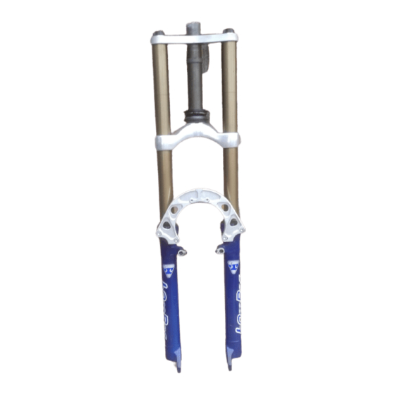
- Page 1 Jr T...
- Page 2 Ø28.6 adjuster, rebound damping adjustment controlled by adjuster inside each fork leg. Jr T • Stanchion tube secured to the crown and upper plate. The system is equipped with full length 360º slider bushings giving this fork an incredibly smooth stiction free stroke, in addition to un- +0.05...
- Page 3 CORRECT OVERHAULING AND MAINTENANCE 1. Where specified, assemble and disas- semble the shock absorption system using MARZOCCHI special tools only. 2. On reassembling the suspension sys- Jr T tem, always use new seals. 3. If two screws are close one to the other, always tighten using a 1-2-1 sequence.
- Page 4 FAILURES, CAUSES AND REMEDIES This paragraph reports some failures that may occur when using the fork. It also indicates possible causes and suggests a remedy. Always refer to this table before doing any repair work. Jr T FAILURES CAUSES REMEDIES Excessive oil build up on stanchions 1.
- Page 5 Installing the Jr.T fork on a bicycle is a very MOUNTING THE FORK ON THE delicate operation that should be carried FRAME MARZOCCHI forks are based on ad- out with extreme care. FIG. A vanced technology, supported by year- A threadless steer tube is pre-installed on...
- Page 6 (D) to the plate close to the steer tube. upper plate to 9 Nm. IMPORTANT: Loosen the 3 screws (36) on the upper plate before ad- Jr T justing the steering. Tighten the above bolts to the specified torque when fin- ished.
- Page 7 (130 mm) + 3 chion tubes and weaken the whole struc- ture. Jr T WARNING: If steering crown is After any installation always check for the improperly matched with stan-...
- Page 8 Screw the caliper support (42) to the slider instructions closely. components. (20) using the screws (43) and plate (41). Jr T Slacken the lock nut of the quick release IMPORTANT: Clean the mating lever so the hub will fit between the fork surfaces inside and outside slider, sliders.
- Page 9 (see Fig. 1). SION. By turning the adjuster knob clock- Slide out the pre-load sleeve (1). Fit the Jr T wise, the preload is increased up to the supplied hexagon rod (C) into the stan- maximum value equal to 15 mm spring chion tube and into the adjuster inner preload.
- Page 10 – Before starting any operation. please read the diagram below. It shows the quickest procedure and the exact disassembling sequence. Start from the part to be disassembled and then follow the arrows to remove the other parts. DISASSEMBLY DIAGRAM Jr T SPRING CHANGE CARTRIDGE ROD CHANGE...
- Page 11 To change the fork leg oil follow the procedure as described in section “REASSEMBLY” from Fig. 22 to Fig. 25. Jr T Turn the fork leg upside-down and un- screw the foot nut (22) complete with O- ring (21) by the use of a 15 mm socket...
- Page 12 Remove the stop ring (15) from the slider the slider. slider using a small screwdriver. by placing the screwdriver bit in one of the three openings on the stop ring. IMPORTANT: when removing the stop ring, make sure not to damage its seat. Jr T...
- Page 13 Pull the bushing out of the slider and make all necessary changes. IMPORTANT: when removing the oil seal, make sure not to damage its seat. Do not reuse any oil seals you have removed. Jr T...
- Page 14 Slip off the stop ring (32) using pointed tube opposite side. Replace the seal ring pliers. (26) if damaged or worn out. Put the valve unit (31) out of the tube in the same sequence as in the figure. Jr T...
- Page 15 GUIDE BUSHING AND SEAL ASSEMBLY FIG. 12 Jr T Check for any debris or dirt lodged be- tween slider and bushing. Insert the guide bushing (18) into the slider making sure it becomes properly seated against slider...
- Page 16 After having overhauled or replaced the valve unit and after having cleaned the inside of the tube, reassemble. Assemble valve unit components (31), in correct sequence. Then fit cartridge rod (11), seal ring (26) and rebound spring (12) into the valve Jr T unit (31).
- Page 17 Turn the slider over and check that car- tridge rod thread (11) is sticking out through the slider hole. If not so, press on Jr T hexagon rod to push out cartridge rod.
- Page 18 Pump stanchion up and down several a better filling. Check that the oil level is times to make sure it slides properly through 95 mm/3.74 in. from the top of the the stroke. stanchion tube, in both legs. Jr T...
- Page 19 Start the complete cap assembly onto stanchion tube thread by hand. Tighten to 12 Nm. Fit the brake arch to the fork leg, and then install fork legs into crown and upper Jr T plate as specified in section “INSTALLA- TION”.
- Page 20 SPECIFIC TOOLS Ref. Item. Description and use 536003 AB Slider protector: to remove the oil seal from the slider R 5068 Oil seal press: to press oil seal into the slider R 5084 Hexagon wrench: to set rebound adjuster Jr T...
Need help?
Do you have a question about the Jr T and is the answer not in the manual?
Questions and answers