
Related Manuals for Motorola solutions APX 8500 E5 CONTROL HEAD


Summary of Contents for Motorola solutions APX 8500 E5 CONTROL HEAD
- Page 1 TWO-WAY RADIOS APX 8500 E5 CONTROL HEAD SNO911 – LAW CONTENTS < PREV NEXT >...
- Page 2 CONTENT 1/1 Content Declaration of Conformity Important Safety Information Software Version Copyrights and Disclaimer Using the IEUTK Getting Started Radio Parts and Controls Fleet map Preparing Your Radio for Use Identifying Radio Controls Identifying Status Indicators General Radio Operation Advanced Features Utilities Radio Care CONTENTS...
-
Page 3: Declaration Of Conformity
Per FCC CFR 47 Part 2 Section 2.1077(a) Responsible Party Name: Motorola Solutions, Inc. Address: Motorola Solutions, Inc., 1303 East Algonquin Road, Schaumburg, IL 60196-1078, U.S.A. Phone Number: 1-800-927-2744 Hereby declares that APX 8500 conforms to FCC Part 15, subpart B, section 15.107(a), 15.107(d), and section 15.109(a) - Page 4 (continued) Class B Digital Device As a personal computer peripheral, this device complies with Part 15 of the FCC Rules. This device complies with Industry Canada license-exempt RSS standard(s). Operation is subject to the following two conditions: This device may not cause harmful interference, and This device must accept any interference received, including interference that may cause undesired operation.
-
Page 5: Important Safety Information
(e.i.r.p.) is not more than that necessary for successful communication. This radio transmitter is approved by Industry Canada to operate with a Motorola Solutions-approved antenna with the maximum permissible gain and required antenna impedance for each antenna type indicated. - Page 6 This device may not cause harmful interference. This device must accept any interference received, including interference that may cause undesired operation. Changes or modifications made to this device, not expressly approved by Motorola Solutions, could void the authority of the user to operate this equipment. CONTENTS <...
- Page 7 To ensure continued compliance with applicable RF exposure limits, use only Motorola Solutions approved, supplied or replacement antennas, batteries, and accessories. • For a list of Motorola Solutions approved accessories please refer to your user manual or visit www.motorolasolutions.com. CONTENTS <...
- Page 8 Distance from Vehicle Body Note: If you are not sure of the rated power of your single-band radio, contact your Motorola Solutions representative or dealer and supply the radio model number found on the radio model label. If you cannot determine the rated power, then assure 3 ft (90 cm) separation for bystanders from the body of the vehicle.
- Page 9 (continued) Table 2 lists the recommended lateral distance for bystanders from the body of a vehicle (For example, truck, van, car, motorcycle) equipped with an approved, properly installed multi-band mobile radio and associated antenna(s). These lateral distances, for multi-band radios, depend on whether the radio is installed on a motorcycle, or on other kinds of vehicles.
- Page 10 Make sure to follow the antenna installation guidelines that are provided in this mobile radio installation manual. • Use only Motorola Solutions approved supplied antenna, or a Motorola Solutions approved replacement antenna. Unauthorized antennas, modifications, or attachments could damage the radio and may result in non-compliance with RF Safety Standards.
- Page 11 (continued) Electromagnetic Interference/Compatibility Nearly every electronic device is susceptible to electromagnetic interference (EMI) if inadequately shielded, designed, or otherwise configured for electromagnetic compatibility. It may be necessary to conduct compatibility testing to determine if any electronic equipment used in or around vehicles or near fixed sites equipped with mobile radio equipment is susceptible to the RF energy emitted by the mobile radio antenna, and if any measures need to be implemented to eliminate or mitigate the potential for EMI between the radio transmitter and the electronic equipment.
- Page 12 (continued) Operational Warnings The following explains the operational warnings: • For Vehicle With Air Bags – Refer to vehicle manufacturer's manual prior to installation of electronic equipment to avoid interference with air bag wiring. – DO NOT place a portable radio in the area over an air bag or in the air bag deployment area. Air bags inflate with great force.
- Page 13 (continued) • Blasting Caps and Blasting Areas To avoid possible interference with blasting operations, turn off your radio when you are near electrical blasting caps, in a blasting area, or in areas posted: “Turn off two-way radio.” Obey all signs and instructions.
- Page 14 If your mobile radio is equipped with a primary or backup battery, you must follow these instructions: • Charge your battery using the approved Motorola Solutions charger. • Use the battery in accordance with its water and/or dust Ingress Protection (IP) rating.
-
Page 15: Software Version
This device may not cause harmful interference. This device must accept any interference received, including interference that may cause undesired operation. Changes or modifications made to this device, not expressly approved by Motorola Solutions, could void the user's authority to operate this equipment. CONTENTS <... - Page 16 Furthermore, Motorola Solutions reserves the right to change any products to improve readability, function, or design. Motorola Solutions does not assume any liability arising out of the applications or use of any product or circuit described herein; nor does it cover any license under its patent rights, nor the rights of others...
- Page 17 Using the IEUTK This Interactive End User Toolkit (IEUTK) covers the basic operation of the APX 8500 E5 Control Head. However, your dealer or system administrator may have customized your radio for your specific needs. Check with your dealer or system administrator for more information.
- Page 18 (continued) The following special notations identify certain items: Example Description Home button or Buttons and keys are shown in bold print or as an icon. Indicates a search function. Edit or change the text item. Back to previous screen. Indicates that a particular action is done. Click to play demo of the procedure.
- Page 19 (continued) Additional Performance Enhancement The following are some of the latest creations designed to enhance the security, quality, and efficiency of the radios. • ® ASTRO 25 Enhanced Data ® ASTRO 25 Enhanced Data is optimized to handle different message sizes and variable update rates from different applications of the radio.
- Page 20 Customer Enterprise Network. • SecureNet SecureNet allows user to perform secured communications on an Analog or Motorola Solutions Data Communication (MDC) channel. The MDC OTAR feature will allow users to perform OTAR activities on an MDC channel.
- Page 21 (continued) • Conventional Talkgroup and Radio Scan Enhancements A few enhancements have been made to the Conventional Talkgroup at the system. These enhancements improve the Scan feature operation significantly when multiple agencies are using a single conventional radio frequency channel. These enhancements allow users to use Selective Squelch to operate on only the subset of talkgroups that are relevant to the users rather than all talkgroups on the channel.
-
Page 22: Getting Started
GETTING STARTED This chapter explains the basics of the mobile radio. CONTENTS < PREV NEXT >... -
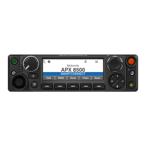
Page 23: Radio Parts And Controls
GETTING STARTED Radio Parts and Controls E5 Control Head Bluetooth Orange Power Volume Screen Mode Pairing Location Button Button Indicators Knob Display Knob Indicator Emergency Conv Menu Menu ZNDN ZNDN ZNUP ZNUP MUTE SCAN SCNL MUTE WIFI RSSI PRFL WIFI PRFL REKY Accessory Port... - Page 24 GETTING STARTED (continued) Keypad Microphone These radio controls/buttons are programmable. CONTENTS < PREV NEXT >...
- Page 25 FLEET MAP 1-7 Information redacted, please contact your local trainer or contact SNO911 Wireless Technology CONTENTS < PREV NEXT >...
- Page 26 FLEET MAP 8-14 Information redacted, please contact your local trainer or contact SNO911 Wireless Technology CONTENTS < PREV NEXT >...
- Page 27 FLEET MAP 15-21 Information redacted, please contact your local trainer or contact SNO911 Wireless Technology CONTENTS < PREV NEXT >...
- Page 28 FLEET MAP 22-29 Information redacted, please contact your local trainer or contact SNO911 Wireless Technology CONTENTS < PREV NEXT >...
-
Page 29: Preparing Your Radio For Use
GETTING STARTED Preparing Your Radio for Use Turning On/Off the Radio Procedure: Power Press and hold the Power Button to power on the radio. Button After a short time, the red, yellow, and green LEDs light up. The display then shows the following: •... -
Page 30: Validating Compatibility During Power Up
GETTING STARTED Preparing Your Radio for Use Validating Compatibility During Power Up The radio validates and updates the software and hardware of your control head(s) during power up. During validation, the display shows Maintenance Mode Remote Device promptly followed by other maintenance statuses. -
Page 31: Adjusting The Volume
GETTING STARTED Preparing Your Radio for Use Adjusting the Volume To increase the volume, rotate the Volume Knob clockwise. To decrease the volume, rotate the Volume Knob counterclockwise. Volume Knob CONTENTS < PREV NEXT >... -
Page 32: Identifying Radio Controls
GETTING STARTED Identifying Radio Controls Programmable Features Any reference in this manual to a control that is “preprogrammed” means that the control must be programmed by a dealer or a qualified radio technician using the radio’s programming software, in order to assign a feature to that control. - Page 33 GETTING STARTED (continued) • Assignable Radio Functions Site Display/Search (Trunking Only) • Call Alert – Allows the radio to function like a – Short Press: Displays the current site ID and pager, or to verify if a radio is active on the Received Signal Strength Indivator (RSSI) system.
- Page 34 GETTING STARTED (continued) Assignable Settings or Utility Functions • Dim – Short Press changes the display brightness, while Long Press toggle between day/night mode. • – Keypad Mute Toggles Keypad tones on or off. CONTENTS < PREV NEXT >...
-
Page 35: Accessing The Preprogrammed Functions
GETTING STARTED Identifying Radio Controls Accessing the Preprogrammed Functions You can access various radio functions through one of the following ways: • A short or long press of the relevant programmable buttons. • Use the Menu Select Buttons. Emergency (Orange) Button* Menu Select Buttons* * These programmable buttons support the One Touch Button feature. - Page 36 GETTING STARTED (continued) Menu Select Buttons The Menu Select buttons allow to access the menu entries of features. Your radio may be preprogrammed differently from the following example, but the steps for selecting a channel may appear as shown below: Press the Menu Select button directly below Chan.
- Page 37 GETTING STARTED (continued) Dimmer Button Use this button to adjust the brightness of the display. Press and hold to toggle between day and night mode. 4-Way Navigation Buttons (on keypad mic) Use these buttons to scroll up, down, left, or right. Press and release one of the button to scroll from one entry to the next one.
-
Page 38: Push-To-Talk (Ptt) Button
GETTING STARTED Identifying Radio Controls Push-To-Talk (PTT) Button The PTT button on the side of the radio serves two basic purposes: • While a call is in progress, the PTT button allows the radio to transmit to other radios in the call. Press and hold down PTT button to talk. -
Page 39: Identifying Status Indicators
GETTING STARTED Identifying Status Indicators Status Icons The liquid crystal display (LCD) of your radio shows the radio status, text entries, and menu entries. The following are the icons that appear on the radio’s display. Receiving Monitor (Carrier Squelch) Radio is receiving a call or data. Selected channel is being monitored (during conventional operation only). - Page 40 GETTING STARTED (continued) User Login Indicator (IP Packet Data) Priority Channel Scan • On = User is currently associated with the • Blinking dot = Radio detects activity on radio. channel designated as Priority-One. • Blinking = Device registration or user •...
- Page 41 GETTING STARTED (continued) LTE Signal Indicating ARS user logged in successfully with LTE system. LTE Signal The radio is receiving LTE signal with ARS user logged in. LTE Signal The radio is transmitting LTE signal with ARS user logged in. LTE Signal The radio is receiving and transmitting LTE signal with ARS user logged in.
-
Page 42: Led Indicators
GETTING STARTED Identifying Status Indicators LED Indicators LED Indicators Yellow Green CONTENTS < PREV NEXT >... -
Page 43: Led Indications
GETTING STARTED Identifying Status Indicators LED Indications The LED Indication shows the operational status of your radio. A qualified technician can permanently disable the LED indication by preprogramming it. Indication Status Radio is transmitting. Solid red Radio is transmitting at low battery condition or detects an incompatible battery. Blinking red Radio is transmitting an emergency alarm or call. - Page 44 GETTING STARTED (continued) Indication Status Channel is busy in conventional mode. Solid yellow Radio is receiving a secured transmission. Blinking yellow Radio is powering up or is on a non-priority channel while in the Scan List Programming mode. Solid green Radio is receiving an individual or telephone call or is on a Priority-Two channel while in the Scan List Programming mode.
-
Page 45: Intelligent Lighting Indicators
GETTING STARTED Identifying Status Indicators Intelligent Lighting Indicators This feature temporarily changes the radio’s display backlight color and the display background color to help signal that a radio event has occurred. Backlight and Bar Color Notification When The radio initiates an emergency alarm or call. Orange Emergency Alerts The radio receives an emergency alarm or call. - Page 46 GETTING STARTED (continued) Orange Emergency Alerts Critical Alerts CONTENTS < PREV NEXT >...
- Page 47 GETTING STARTED Identifying Status Indicators Channel Color Backlight The Channel Color Backlight feature allows you to identify your selected channel based on the color of the channel text and the menu options on the home screen. This color is also reflected on the control head buttons, knobs, keypad microphone depending on the Customer Programming Software (CPS) configuration of your radio.
-
Page 48: Alert Tones
GETTING STARTED Identifying Status Indicators Alert Tones Your radio uses alert tones to inform you of your radio’s condition. The following table lists these tones and when they occur. You Hear Tone Name Heard Private Conversation When a private call is received. high-pitched tones Four high-... - Page 49 GETTING STARTED (continued) A Series of When a channel is now available for your previously requested transmission. Two Short Automatic Call Back Talk When the PTT button is pressed, this tone indicates that the system is accepting your High-Pitched Permit (Optional) transmission.
- Page 50 GETTING STARTED (continued) When the PTT button is pressed, this tone indicates that the the system is out of Talk-Prohibit service. When the PTT button is pressed, this tone indicates that the channel is busy with the Smart PTT Inhibit Smart PTT feature enabled.
-
Page 51: General Radio Operation
GENERAL RADIO OPERATION This chapter explains the general radio operations of your radio. CONTENTS < PREV NEXT >... -
Page 52: Selecting A Zone
GENERAL RADIO OPERATION Selecting a Zone A zone is a group of channels. Do one of the following to select a radio channel. You can use these options interchangeably depending on your preference and the programmed functions. Procedure: DEMO [Menu] From the home screen, scroll left or right to Zone. -
Page 53: Selecting A Radio Channel
GENERAL RADIO OPERATION Selecting a Radio Channel A channel is a group of radio characteristics, such as transmit/receive frequency pairs. Procedure: [Mode Knob] If channel is set as the primary mode, Turn the Mode Knob until the display shows the desired channel. -
Page 54: Receiving And Responding To A Radio Call
GENERAL RADIO OPERATION Receiving and Responding to a Radio Call Once you have selected the required channel and/or zone, you can proceed to receive and respond to calls. The radio shows different indicators based on the system the radio is configured. •... -
Page 55: Receiving And Responding To A Talkgroup Call
GENERAL RADIO OPERATION Receiving and Responding to a Radio Call Receiving and Responding to a Talkgroup Call When you receive a talkgroup call (while on the home screen) the radio displays the following depending on the system your radio is configured to: •... -
Page 56: Switching Between Repeater Or Direct Operation Button
GENERAL RADIO OPERATION Switching Between Repeater or Direct Operation Button The Direct or Talkaround Operation allows you to bypass the repeater and connect directly to another radio. The transmit and receive frequencies are the same. Procedure: [Menu] From the home screen, scroll left or right to Dir. Press the Menu Select button directly below Dir. -
Page 57: Monitor Features
GENERAL RADIO OPERATION Monitor Features The monitor feature is used to make sure that a channel is clear before transmitting. The lack of static on a digital channel when the users switch from analog to digital radios is not an indication that the radio is malfunctioning. -
Page 58: Monitoring A Channel
GENERAL RADIO OPERATION Monitor Features Monitoring a Channel Conventional Modes Trunked Modes Procedure: Procedure: Lift the microphone off the hook. Lift the microphone off the hook. Listen for activity on that channel. Press the PTT button. Adjust the Volume Knob if necessary. If you hear two, short, high-pitched tones, or if you hear no tone and the indicator lights up... -
Page 59: Monitoring Conventional Mode
GENERAL RADIO OPERATION Monitor Features Monitoring Conventional Mode This feature allows you to monitor channel traffic on conventional channels by defeating the coded squelch. Thus, you can to listen to another active user on the channel. This way, you may be prevented from talking over someone else’s conversation. -
Page 60: Advanced Features
ADVANCED FEATURES This chapter explains the operations of the features available in your radio. CONTENTS < PREV NEXT >... -
Page 61: Scan Lists
ADVANCED FEATURES Scan Lists Scan lists are created and assigned to individual channels/groups. Your radio scans for voice activity by cycling through the channel/group sequence specified in the scan list for the current channel/group. Your radio supports different types of Scan Lists: •... -
Page 62: Viewing A Scan List
ADVANCED FEATURES Scan Lists Viewing a Scan List Procedure: From the home screen, scroll left or right to ScnL. Press the Menu Select button directly below ScnL. Scroll up or down to view the members on the list. Press the Home button to exit the current display and return to the home screen. Menu Select Buttons CONTENTS... -
Page 63: Editing The Scan List
ADVANCED FEATURES Scan Lists Editing the Scan List This feature allows you to change scan list members Perform one of the following actions to select and priorities. another channel that you want to add or delete then repeat step 4. Otherwise, proceed to the next step. -
Page 64: Changing The Scan List Status
ADVANCED FEATURES Scan Lists Changing the Scan List Status Procedure: Long press the preprogrammed Scan side button. Scroll up or down to the member you want to edit. Press the Select button once to add the currently displayed channel to the scan list. Press the Select button one or more times to change the scan list status icon of the currently displayed channel. -
Page 65: Viewing And Changing The Priority Status
ADVANCED FEATURES Scan Lists Viewing and Changing the Priority Status Press the Menu Select button directly below Sel one or more times to change the priority status of the current displayed channel. Press the Menu Select button one or more times to toggle between different status of the Scan List status icon of the currently displayed channel. -
Page 66: Turning Scan On Or Off
ADVANCED FEATURES Scan Turning Scan On or Off This feature allows you to monitor traffic on different channels by scanning a preprogrammed list of channels. Scanning is halted if you initiate a call and resumes when the call has ended. Procedure: [Menu] From the home screen, scroll left or right to... - Page 67 ADVANCED FEATURES Scan Turning Scan On While Disregarding the Squelch Code (Conventional Channels Only) You can still receive fleetwide, system-wide, dynamic regrouping, incoming telephone interconnect, and Private Conversation/Call Alert calls while scanning for activity. You may respond to these types of calls as you would normally on the selected channel. However, when scanning different channels while in talkgroup scan, incoming Private Conversation/Call Alert calls may be missed.
-
Page 68: Restoring Priorities In A Scan List
ADVANCED FEATURES Scan Restoring Priorities in a Scan List To restore the original channel priorities in a scan list, perform one of the following actions: • Turn scan off, and then on. • Change the channel. • Turn off the radio, and then turn it back on. CONTENTS <... -
Page 69: Emergency Operation
ADVANCED FEATURES Emergency Operation The Emergency feature is used to indicate a critical situation. An emergency signal overrides any other communication over the selected channel. If the Orange button is preprogrammed to send an emergency signal, this signal overrides any other communication over the selected channel. -
Page 70: Special Considerations For Emergencies
ADVANCED FEATURES Emergency Operation Special Considerations for Emergencies • If you press the Emergency button while in a channel that has no emergency capability, a low-pitched tone sounds. • If you change to a channel/mode with no Emergency capability while in Emergency operation, the following occurs: The display shows NO EMERGENCY. - Page 71 ADVANCED FEATURES Emergency Operation Exiting Emergency Operation If an Emergency operation is triggered on your radio, the dispatch console or radios configured as Supervisor can also exit the Emergency operation. Procedure: To exit Emergency operation, press and hold the preprogrammed Emergency button. CONTENTS <...
-
Page 72: Sending An Emergency Alarm
ADVANCED FEATURES Emergency Operation Sending an Emergency Alarm This feature allows you to send a data transmission, which identifies the radio sending the emergency, to the dispatcher. Procedure: DEMO Press the preprogrammed Emergency button. A tone sounds, the LED blinks red momentarily, and the radio displays EMERGENCY. A dispatcher acknowledgment Ack received display follows. -
Page 73: Trunking System Controls
ADVANCED FEATURES Trunking System Controls Out-of-Range Radio When your radio goes out of the range of the system, it can no longer lock onto a control channel. Procedure: DEMO You hear a low-pitched tone. AND/OR The display shows the currently selected zone/channel combination and Out of range notification. Your radio remains in this out-of-range condition until: It locks onto a control channel. -
Page 74: Site Trunking Feature
ADVANCED FEATURES Trunking System Controls Site Trunking Feature If the Zone Controller loses communication with any site, that site reverts to site trunking. When this occurs, you can communicate only with the radios within your trunking site. The display shows the currently selected zone/channel and the Site Trunking message. Note: When this occurs, you can communicate only with other radios within your trunking site. -
Page 75: Viewing The Current Site
ADVANCED FEATURES Trunking System Controls Viewing the Current Site Procedure: [Preprogrammed Button] Press the preprogrammed Site Search button. The display momentarily shows the name of the current site and its corresponding Received Signal Strength Indicator (RSSI). [Menu] From the home screen, scroll left or right to RSSI. Press the Menu Select button directly below RSSI. -
Page 76: Changing The Current Site
ADVANCED FEATURES Trunking System Controls Changing the Current Site Procedure: [Preprogrammed Button] Press and hold down the preprogrammed Site Search button. You hear a tone and the display momentarily shows Scanning site. When the radio finds a new site, it returns to the home screen. [Menu] From the home screen, scroll left or right to RSSI. -
Page 77: Turning Wi-Fi On Or Off
ADVANCED FEATURES Wi-Fi Turning Wi-Fi On or Off You can connect your radio to a Wi-Fi network for wireless programming. Your service administrator preprograms the Wi-Fi Service Set Identifier (SSID) or network name that your radio can connect to. Procedure: [Menu] From the home screen, scroll left or right to WiFi. -
Page 78: Selecting Wi-Fi Network
ADVANCED FEATURES Wi-Fi Selecting Wi-Fi Network This feature allows you to view and select the Scroll up or down though the list and press the Menu Select button directly below Sel to connect available Wi-Fi network. to the selected network. Radio displays the Wi-Fi status, the selected Procedure: network, and the signal strength. -
Page 79: Checking The Wi-Fi Configuration And Status Of The Radio
ADVANCED FEATURES Wi-Fi Checking the Wi-Fi Configuration and Status of the Radio Procedure: Searching Looking for available Wi-Fi networks that have been [Menu] preprogrammed into the radio. From the home screen, scroll left or right to Connecting In the process of connecting to a WiFi. - Page 80 UTILITIES This chapter explains the operations of the utility functions available in your radio. CONTENTS < PREV NEXT >...
-
Page 81: Selecting A Radio Profile
UTILITIES Selecting a Radio Profile This feature allows you to manually switch the visual Procedure: and audio settings of the radio. The display, [Menu] backlight, alert tones, and audio settings are defined From the home screen, scroll left or right to Prfl. according to the preprogrammed radio settings of Press the Menu Select button directly below Prfl each radio profile. -
Page 82: Controlling The Display Backlight
UTILITIES Controlling the Display Backlight You can enable or disable the radio display backlight as needed, if poor light conditions make the display or keypad difficult to read. Depending on how your radio is preprogrammed, you can also maintain a minimum backlight level on the radio's front display. -
Page 83: Turning Keypad Tones On Or Off
UTILITIES Turning Keypad Tones On or Off You can enable and disable keypad tones as needed. Procedure: [Menu] From the home screen, scroll left or right to Mute. Press the Menu Select button directly below Mute. The display momentarily shows Tones off, indicating that the keypad tones are disabled. -
Page 84: Radio Care
RADIO CARE This chapter explains the radio care. CONTENTS < PREV NEXT >... - Page 85 RADIO CARE Radio Care The following are suggestions to assist you in troubleshooting possible operating problems. CAUTION: The cables that connect to the rear of the radio could have live voltage on some of their pins. Do not remove or reconnect these cables. Only a qualified radio technician should perform this task.
-
Page 86: Cleaning The External Surface Of The Radio
RADIO CARE Radio Care Cleaning the External Surface of the Radio CAUTION: Do not use solvents to clean your radio. Spirits may permanently damage the radio housing. Do not submerge the radio in the detergent solution. To clean the external surfaces of your radio, follow the procedure described next. Combine one teaspoon of mild dishwashing detergent to one gallon of water (0.5% solution). -
Page 87: Cleaning The External Plastic Surface
RADIO CARE Radio Care Cleaning the External Plastic Surface The detergent-water solution should be applied sparingly with a stiff, non-metallic, short-bristled brush to work all loose dirt away from the radio. A soft, absorbent, lint-free cloth or tissue should be used to remove the solution and dry the radio. -
Page 88: Proper Ways To Handle The Radio
RADIO CARE Radio Care Proper Ways to Handle the Radio • Do not pound, drop, or throw the radio unnecessarily. • Never carry the radio by the antenna. • Avoid subjecting the radio to an excess of liquids. • Do not submerge the radio. •... -
Page 89: Radio Service And Repair
Motorola Solutions makes the finest service available to those desiring reliable, continuous communications on a contract basis. For a contract service agreement, contact your nearest Motorola Solutions service or sales representative, or an authorized Motorola Solutions dealer.
Need help?
Do you have a question about the APX 8500 E5 CONTROL HEAD and is the answer not in the manual?
Questions and answers