Price FFU Series Installation And Service Manual
Fan filter unit
Hide thumbs
Also See for FFU Series:
- Installation and service manual (64 pages) ,
- User manual (4 pages)

Related Manuals for Price FFU Series


Summary of Contents for Price FFU Series
- Page 1 MANUAL – INSTALLATION + SERVICE Fan Filter Unit FFU Series v100 – Issue Date: 07/10/20 © 2018 Price Industries Limited. All rights reserved.
-
Page 2: Table Of Contents
FAN FILTER UNIT TABLE OF CONTENTS Product Overview Balancing Read and Save These Instructions ........ 1 Balancing: Technical Note: Design with VAV/Constant Before You Start ............1 Flow Boxes and Ducted Applications ......19 Introduction ..............2 Balancing Un-ducted Supply Units ......20 Balancing Ducted Supply –... -
Page 3: Product Overview
Extreme caution should be taken to avoid contact with filter media. Touching filter media may result in filter failure. Damageto filters can occur during installation or during leak qualification testing. The filters supplied by Price have been 100% tested and certified by the manufacturer to be free of defects and leaks. -
Page 4: Introduction
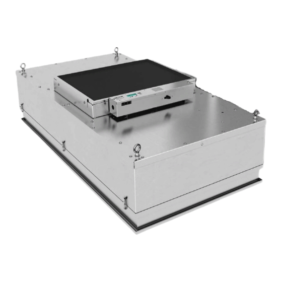
Introduction Price Fan Filter Units (FFU) are ceiling module diffusers consisting of a fan/motor assembly and Roomside Removable (RSR), or Bench Top Replaceable (BTR) filters. The module is designed to provide unidirectional vertical airflow of filtered, clean air over a cleanroom space. -
Page 5: Installation Instructions Module Installation
INSTALLATION INSTRUCTIONS Module Installation The Price FFU will come completely assembled from the factory with the exception of the HEPA/ULPA filters, which will ship in its own carton, and the speed controller wall kits (if selected). Sample line string for Room Side Replaceable filter:... -
Page 6: Speed Controller Installation & Operation
FAN FILTER UNIT INSTALLATION INSTRUCTIONS Speed Controller Installation & Operation Refer to Factory Label to determine which speed controller is on the unit and use the following tableto find the appropriate installation instructions. Sample line string: FFU-1-4//I/SUPPLY/24/48//RSR/HEPA/FC/ECM/115/CF/R+TMB/FL+ML+BACnet/BFC/TC/DSW-115// ASSP///WPF/PL-AL/F-AL/PL-B12/F-B12 Speed Controller Page Reference PSCSC/WK ECMSC... -
Page 7: Ecmsc
WM/F-EM Step 2: If ECMSC is to be controlled using analog voltage signal from BAS (others) or Price WMSC, please remove ECMSC from control box. Connect 0-10VDC & COMMON to BAS SIGNAL & BAS COMMON on back of ECMSC (make sure to feed wires through grommet on control box). -
Page 8: Bacnet Flow Controller (Bfc)
FAN FILTER UNIT INSTALLATION INSTRUCTIONS BACnet Flow Controller (BFC) Installation Sample line string: FFU-1-X//I/SUPPLY/24/48//RSR/HEPA/FC/ECM/115/CF/R+TMB/BACnet/BFC/TC/DSW-115//ASSP///WPF/ PL-AL/F-AL/PL-B12/F-B12 Step 1: Wire unit according to appropriate wiring diagram. If Power Cord (PC) option is selected, simply insert plug end into electrical socket. NOTE: Polarity is important and must be observed. It is also vital that the 24 VAC common side of the transformer be Earth grounded. - Page 9 FAN FILTER UNIT INSTALLATION INSTRUCTIONS Airflow Setpoint For setting the airflow setpoint on the FFU, please locate the section for the correct controller below (either ECMSC or BFC). ECMSC SPEED CONTROLLER POTENTIOMETER (POT) MEASURE (+) VDC MEASURE (-) VDC Step 1: Determine test point voltage (VDC) from the formula based on the desired airflow using the appropriate chart below. Supply - Constant Flow –...
- Page 10 FAN FILTER UNIT INSTALLATION INSTRUCTIONS Supply - Constant Torque – Clean Filters (Forward Curved) Voltage Velocity 24x24 24x36 24x48 Volt BTR/FC RSR/FC BTR/FC RSR/FC BTR/FC RSR/FC CFM + 188 CFM + 156 CFM + 155 CFM + 142 CFM + 212 CFM + 179 45-90 VDC =...
- Page 11 FAN FILTER UNIT INSTALLATION INSTRUCTIONS Step 2: If using potentiometer/manual adjustment, rotate the potentiometer (POT/DIAL) dial on the outside of the box with a screwdriver until the test point voltage is achieved. NOTE: ECM Speed Controllers have 2 modes: manual adjust and BAS (Building Automation System). Standard manual control outputs are shown below: Measurement Tab Voltage Motor Control...
- Page 12 FAN FILTER UNIT INSTALLATION INSTRUCTIONS Airflow Setpoint BFC Step 1: Determine if BFC will be controlled using local control, BAS analog voltage signal, or BACnet. The control mode can be confirmed by observing the cycling status readout on the LCD. NOTE: The control hierarchy is BACnet >...
- Page 13 FAN FILTER UNIT INSTALLATION INSTRUCTIONS Exhaust - Constant Flow – Clean Filters (Forward Curved) Voltage Velocity 24 x 48 Volt RSR - FC 45-135 ECM% = (CFM/7.63) - 18 45-135 ECM% = (CFM/7.63) - 18 45-135 ECM% = (CFM/7.53) - 18 Exhaust - Constant Torque –...
-
Page 14: Filter Installation
FAN FILTER UNIT INSTALLATION INSTRUCTIONS Filter Installation Room Side Replaceable Filter (RSR) Sample line string: FFU-1-X//I/SUPPLY/24/48//RSR/HEPA/FC/ECM/115/CF/R+TMB/BACnet/BFC/TC/DSW-115//ASSP///WPF/ PL-AL/F-AL/PL-B12/F-B12 Please refer to the FTR Room-side Replaceable Filter (RSR) Quick Start Guide. Bench Top Replaceable Filter (BTR) Sample line string: FFU-1-1//I/24/48/BTR/FC/ECM/115/10//CF//HEPA//BFC////DSW-115//PC-115//TMB/ASSP/// FL+ML+BACnet/// WPFH/PL-AL///PL-B12/ Please refer to the FTR Room-side Replaceable Filter (BTR) Quick Start Guide. -
Page 15: Accessories
Sample line string: FFU-1-X//I/SUPPLY/24/48//RSR/HEPA/FC/ECM/115/CF/R+TMB/BACnet/BFC/TC/DSW-115/PC-115/ASSP/ INJ//WPF/PL-AL/F-AL/PL-B12/F-B12 Every FFU from Price is supplied with an aerosol sample/static pressure port. The ASSP is a ¼” port used for measuring plenum static pressure as well as sampling aerosol concentrations above the filter. On the FFU with BTR filter there are two ports on the center strip of the filter than can function as the ASSP, however if the LED indicator option has been selected, one port will be used for the LED installation. -
Page 16: Filter/Motor Indicator Led (Ml/Fl) - Psc Units
FAN FILTER UNIT INSTALLATION INSTRUCTIONS Filter/Motor Indicator LED (ML/FL) - PSC Units Sample line string: FFU-1-X/I/SUPPLY/24/48//RSR/HEPA/FC/PSC/115//R+TMB/FL+ML/PSC-WK/TC/DSW-115//ASSP///WPF/ PL-AL/F-AL/PL-B12/F-B12 LED Installation (BTR Units only) Step 1: Take LED cable assembly out of FFU-1-X Plenum. Step 2: Remove well nut in center port of BTR filter. CABLE ASSEMBLY STATIC PRESSURE PORT Step 3: Remove threaded standoff and lock washer from LED cable assembly. - Page 17 FAN FILTER UNIT INSTALLATION INSTRUCTIONS Step 5: Put lock washer and threaded standoff back on cable and tighten to LED. BTR FACE INSTALLED LED THREADED STANDOFF THROUGH FILTER CHANNEL Step 6: With two (2) people holding the unit, pull cable back through plenum until plenum can rest on top of filter. CABLE ASSEMBLY Step 7: Install the filter, refer to the filter installation section of this manual.
- Page 18 FAN FILTER UNIT INSTALLATION INSTRUCTIONS LED Operation Option Code Action Notes Color Indicates normal operation until filter pressure drop exceeds Green None calibrated pressure drop (factory set at 1.5x clean filter pressure). Filter LED Indicates filter pressure drop has exceeded calbirated setting (factory Yellow Change Filter set at 1.5x clean filter pressure.
- Page 19 FAN FILTER UNIT INSTALLATION INSTRUCTIONS Step 2: Calculate number of turns required based on difference between factory set point and desired set point using the following chart. Table 2. Set Point Adjustment RSR FILTER LED SET POINT ADJUSTMENT 1.00 1.00 0.90 0.90 0.80...
-
Page 20: Filter/Motor Indicator Led (Ml/Fl) - Ecm Units
FAN FILTER UNIT SERVICE INSTRUCTIONS Filter/Motor Indicator LED (ML/FL) - ECM Units Sample line string: FFU-1-X/I/SUPPLY/24/48//RSR/HEPA/FC/ECM/115//R+TMB/FL+ML+BACnet/BFC/TC/DSW-115//ASSP/// WPF/PL-AL/F-AL/PL-B12/F-B12 LED Operation LED Color Unit Status* Action Notes Indicates normal operation until pressure drop exceeds calibrated pressure Green Normal None drop (factory set a 1.5x clean filter pressure). Indicates filter pressure drop has exceeded calibrated setting (factory set at Change or calibrate Yellow... -
Page 21: Balancing
For any additional information, or troubleshooting assistance on systems and design with fan filter units used in sequence with a variable upstream air source, contact Price Industries Fan Filter help at criticalenvironments@priceindustries.com, or dial (204) 654- 5613 option 5. -
Page 22: Balancing Un-Ducted Supply Units
FAN FILTER UNIT BALANCING Balancing Un-ducted Supply Units UN-DUCTED SUPPLY UNITS, NEGATIVE PRESSURE PLENUM Step 1: Ensure the unit and filter is properly installed. Step 2: Turn on FFU and set to desired airflow. See Airflow Setpoint section to determine initial setpoint. Step 3: Measure airflow using flow hood and compare against scheduled flow. -
Page 23: Balancing Ducted Supply - Pressure Independent
FAN FILTER UNIT BALANCING Balancing Ducted Supply – Pressure Independent and Dependent Airflow Control NOTE: If there is a pressure independent device upstream of the FFU then PSC or ECM with constant torque motors should be used. DUCTED UNIT: CONSTANT FLOW DUCTED UNIT: CONSTANT TORQUE FFU WITH If FFU is not already installed: FFU WITH UPSTREAM PRESSURE... - Page 24 FAN FILTER UNIT BALANCING If the FFU is ducted and removing the duct is not possible, follow the below instructions for balancing: Step 1: Turn off primary air source. Step 2: Install an air pressure measurement device (i.e. Pitot tube) in the duct prior to the FFU inlet. Step 3: Power up FFU and set speed controller to desired airflow.
-
Page 25: Balancing Ducted Supply - Pressure Independent
FAN FILTER UNIT BALANCING Balancing Ducted Supply – Pressure Independent and Dependent Airflow Control NOTE: If a ducted return or return mixing box is used, a PSC, ECM Constant Torque or ECM Constant Flow (preferred) can be used. FFU WITH DUCTED RETURN FFU WITH RETURN MIXING BOX Step 1: If return mixing box is used, turn primary air off. -
Page 26: Service Instructions
FAN FILTER UNIT SERVICE INSTRUCTIONS Pre-Filter Cleaning Step 1: Gain access to the top of the unit by removing adjacent ceiling, or access panel. Step 2: Remove filter by pushing filter to one side and sliding it out from under the brackets (non-ducted), or remove filter access door (ducted). -
Page 27: Motor Change
FAN FILTER UNIT SERVICE INSTRUCTIONS Motor Change Top Access Motor/Blower Assembly Sample line string: FFU-1-X//I/24/48/RSR/BC/ECM/115/10//CT//HEPA//ECMSC//WK-ECMSC//DSW-115//PC-115//TMB/ASSP/ INJ/////WPFH/PL-AL/F-AL//PL-B12/F-B12 Step 1: Gain access to the top of the unit by removing adjacent ceiling, or access panel. Step 2: Remove filter by pushing filter to one side and sliding it out from under the brackets (non-ducted), or remove the duct collar/pre-filter housing and pre-filter (if applicable) via screws (ducted) to expose motor assembly. - Page 28 Step 8: Replace with the new motor/blower assembly and reassemble by reversing the above steps. For information on how to order replacement motor/blowers, contact your local Price Sales Representative. NOTE: Step 9: Double check airflow to ensure that set point has not changed.
-
Page 29: Room Side Accessible Motor/Blower Assembly
FAN FILTER UNIT SERVICE INSTRUCTIONS Room Side Accessible Motor/Blower Assembly Sample line string: FFU-1-X//I/SUPPLY/24/48//RSR/HEPA/FC/ECM/115/CF/R+TMB/BACnet/BFC/TC/DSW-115/PC-115/ASSP/INJ//WPF/PL-AL/F- AL/PL-B12/F-B12 NOTE: Disconnect the unit from the electrical power source before attempting any service. Electrical service should be performed by a licensed electrician or authorized service technician. NOTE: Disconnect the unit from the electrical power source before attempting any service. - Page 30 FAN FILTER UNIT SERVICE INSTRUCTIONS Step 5: Remove the nuts securing the blower housing using a 7/16” socket wrench (or equivalent). 2X2 FORWARD CURVED BLOWER HOUSING 2X3 AND 2X4 FORWARD CURVED BLOWER HOUSING NOTE: A 7/16” ratchet with extension is recommended for ease of access for unfastening. 2X3 AND 2X4 BACKWARD CURVED BLOWER HOUSING NUTS LOCATED ON TOP OF BLOWER HOUSING...
- Page 31 Step 12: Replace with the new motor/blower assembly and reassemble by reversing the above steps. Step 13: Double check airflow to ensure that set point has not changed. NOTE: For information on how to order replacement motor/blowers, contact your local Price Sales Representative. priceindustries.com | FAN FILTER UNIT - Manual...
-
Page 32: Room Side Accessible Controls
FAN FILTER UNIT SERVICE INSTRUCTIONS Room Side Accessible Controls Sample line string: FFU-1-X//I/SUPPLY/24/48//RSR/HEPA/FC/ECM/115/CF/R+TMB/BACnet/BFC/R+TC/DSW-115/PC-115/ ASSP/INJ//WPF/PL-AL/F-AL/PL-B12/F-B12 Step 1: Remove diffuser perforated face by turning quarter turn fasteners holding face in place. NOTE: Safety cables will be attached to the diffuser face, but care should be taken to ensure that diffuser face does not swing and injure anyone. - Page 33 FAN FILTER UNIT SERVICE INSTRUCTIONS Step 3: Turn all cam latch filter retainers to the open position. Step 4: Remove filter by handling frame; Extreme caution should be taken when removing the filter if the filter is to be reinstalled. Touch the filter by the frame only;...
- Page 34 FAN FILTER UNIT SERVICE INSTRUCTIONS Step 7: Carefully remove the baffle and the retainer bracket from the module. BAFFLE AND RETAINER BRACKET REMOVAL Step 8: For 24 x 36" units with BC option, remove the housing to access the control lid. Step 9: Remove the control lid from the inside of the plenum using a 7/16"...
-
Page 35: Troubleshooting
FAN FILTER UNIT TROUBLESHOOTING Troubleshooting – Changing Motor Programs The motors have the ability to function as either constant flow or constant torque. This provides the ability to change motor programs without the need to reprogram the motor. NOTE: Changes will only take effect upon restarting the motor (must be powered off and then back on) and cannot be made live. Switching from constant flow to constant torque: To switch the motor from constant flow to constant torque all that is required is to open the connection of the white wire as shown. -
Page 36: Troublehsooting Tips
3. Check control mode on speed controller and ensure setpoint is not 0%. 4. Check control harness between speed controller and motor If experiencing further issues with unit, contact Price Industries Fan Filter help at: By Email: criticalenvironments@priceindustries.com By Phone: (204) 654-5613 option 5... -
Page 37: Replacement Parts
REPLACEMENT PARTS BTR Unit Replacement Parts HEPA Filters Size Quantity Description Price Part Number Filter, HEPA, 99.99% FFU 24 x 24 x 3.06" 042299-011 Filter, HEPA, 99.99% FFU 24 x 36 x 3.06" 042299-012 Filter, HEPA, 99.99% FFU 24 x 48 x 3.06"... -
Page 38: Rsr Unit Replacement Parts
REPLACEMENT PARTS RSR Unit Replacement Parts HEPA Filters Size Quantity Description Price Part Number Filter, HEPA, 99.99% FFU 24 x 24 x 3.5" 042299-005 Filter, HEPA, 99.99% FFU 24 x 36 x 3.5" 042299-006 Filter, HEPA, 99.99% FFU 24 x 48 x 3.5"... - Page 39 FAN FILTER UNITS NOTES priceindustries.com | FAN FILTER UNIT - Manual priceindustries.com | FAN FILTER UNIT - Manual...
- Page 40 FAN FILTER UNITS NOTES FAN FILTER UNIT - Manual | priceindustries.com...
- Page 41 FAN FILTER UNITS NOTES priceindustries.com | FAN FILTER UNIT - Manual...
- Page 42 This document contains the most current product information as of this printing. For the most up-to-date product information, please go to priceindustries.com © 2020 Price Industries Limited. All rights reserved.
Need help?
Do you have a question about the FFU Series and is the answer not in the manual?
Questions and answers