Price FFU series Installation And Service Manual
Fan filter unit
Hide thumbs
Also See for FFU series:
- User manual (4 pages) ,
- Installation and service manual (42 pages)

Related Manuals for Price FFU series


Summary of Contents for Price FFU series
- Page 1 MANUAL – INSTALLATION + SERVICE Fan Filter Unit FFU Series v100 – Issue Date: 04/03/18 © 2018 Price Industries Limited. All rights reserved.
-
Page 2: Table Of Contents
FAN FILTER UNIT TABLE OF CONTENTS Product Overview Motor Change ............26 Read & save these instructions ........1 Top Access Motor/Blower Assembly ....... 26 Before you start ............2 Room Side accessible Motor/Blower Assembly ..28 Introduction ..............3 Technical Note: Aerosol Sample and Static Port.. -
Page 3: Product Overview
FAN FILTER UNIT PRODUCT OVERVIEW Read and Save These Instructions Warning! To reduce the risk of fire, electrical shock, or injury to persons, observe the following: A. Installation work and electrical wiring must be done by qualified person(s) in accordance with all applicable codes and standards, including fire-rated construction. -
Page 4: Before You Start
The filters supplied by Price have been 100% tested and certified by the manufacturer to be free of defects and leaks. Price cannot accept responsibility for damage that occurs after shipment, whether through transit, handling or installation, and will not replace filters under Price standard warranty. -
Page 5: Introduction
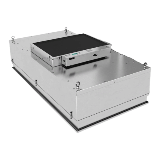
Introduction Price Fan Filter Units (FFU) are ceiling module diffusers consisting of a fan/motor assembly and Roomside Removable (RSR), or Bench Top Replaceable (BTR) filters. The module is designed to provide unidirectional vertical airflow of filtered, clean air over a cleanroom space. -
Page 6: Installation & Service Instructions
INSTALLATION & SERVICE INSTRUCTIONS Diffuser Module Installation The Price FFU will come completely assembled from the factory with the exception of the HEPA/ULPA filters, which will ship in its own carton, and the speed controller wall kits (if selected). NOTE: Do not open the HEPA/ULPA filters until they are ready to be installed in the FFU units. - Page 7 FAN FILTER UNIT INSTALLATION & SERVICE INSTRUCTIONS FIGURE 2: UNIT EYEBOLTS FOR MOUNTING STEP 6: Adjust and level the unit so that it rests on the tees and there is adequate compression on the gasket to warrant a tight seal. Ensure that ceiling grid is properly gasket/sealed to prevent infiltration of unfiltered air from the ceiling plenum into the room side.
-
Page 8: Speed Controllers
FAN FILTER UNIT INSTALLATION & SERVICE INSTRUCTIONS Speed Controllers PSCSC/WK Speed Controller Installation & Operation Sample line string: FFU-1-X//I/24/48/BTR/FC/PSC/115/10////HEPA//PSCSC//WK-PSC//DSW-115////TMB/ASSP//////WPFH/PL-AL///PL-B12/ FIGURE 3: PSC SPEED CONTROLLER WITH WALL KIT OPTION If unit does not have the wall kit (WK) option, proceed to step 11A. Sample line string: FFU-1-X//I/24/48/BTR/FC/PSC/115/10////HEPA//PSCSC/////DSW-115////TMB/ASSP//////WPFH/PL-AL///PL-B12/ STEP 8A: Locate pre-installed electric box for wall-mounted speed controller. -
Page 9: Ecmsc/Wk Speed Controller
FAN FILTER UNIT INSTALLATION & SERVICE INSTRUCTIONS ECMSC/WK Speed Controller Installation and Operation Sample line string below: FFU-HE/24/48/RSR/BC/ECM/115/10//CT//HEPA//ECMSC// WK /DSW/PC/TMB/ATS/ML/FL/WPF/PL-AL/F-AL/PL-B12/F-B12 FIGURE 4: ECMSC/WK If unit does not have the wall kit (WK) option, proceed to STEP 11B. Sample line string: FFU-1-X//I/24/48/RSR/FC/ECM/115/10//CF//HEPA//ECMSC/////DSW-115////RMB/ASSP//////WPFH/PL-AL/F-AL//PL-B12/F-B12 STEP 8B: Locate pre-installed electrical box for wall-mounted speed controller. -
Page 10: Ecmdx/Wk Speed Controller
FAN FILTER UNIT INSTALLATION & SERVICE INSTRUCTIONS Speed Controllers ECMDX/WK Speed Controller Installation and Operation Sample line string: FFU-HE/24/48/RSR/BC/ECM/115/10//CT//HEPA//ECMDX// /DSW/PC/TMB/ATS/ML/FL/WPF/PL-AL/F-AL/PL-B12/F-B12 FIGURE 5: ECMDX WALL KIT SPEED CONTROLLER If unit does not have the wall kit (WK) option, proceed to STEP 11C. Sample line string: FFU-HE/24/48/RSR/BC/ECM/115/10//CT//HEPA//ECMDX//WK/DSW/PC/TMB/ATS/ML/FL/WPF/PL-AL/F-AL/PL-B12/F-B12 FIGURE 6: ECMDX WALL KIT SPEED CONTROLLER... - Page 11 FAN FILTER UNIT INSTALLATION & SERVICE INSTRUCTIONS Sample line string: FFU-HE/24/48/RSR/BC/ECM/115/10//CT//HEPA//ECMSC///DSW/PC/TMB/ATS/ML/FL/WPF/PL-AL/F-AL/PL-B12/F-B12 Wiring should be carried out by a certified electrician and meet national and local electrical codes. NOTE: STEP 12C: If using RSR filter, refer to page 11 for filter installation instructions. NOTE: Ensure that the space is clean, free of debris, and that ducts are cleaned and ready for operation prior to installation of filter STEP 13C: Ensure proper Voltage is hooked up.
-
Page 12: Bacnet Flow Controller (Bfc)
For additional information on BACnet, and the BFC controller, refer to the BACnet Wiring Guidelines, and BFC Manual which are available on the Price Industries website @ priceindustries.com STEP 10D: Wire the unit according to the appropriate wiring diagram found on page 58 – 60. If power cord option is selected, simply insert the plug end into the electric socket. -
Page 13: Filter Installation
The filters supplied by Price have been 100% tested and certified by the manufacturer to be free of defects and leaks. Price cannot accept responsibility for damage that occurs after shipment, whether through transit, handling or installation, and will not replace filters under our standard warranty. - Page 14 FAN FILTER UNIT INSTALLATION & SERVICE INSTRUCTIONS STEP 5 Loosen cam locks on diffuser to prepare filter for installation. Be sure latches are turned inwards so as not to interfere with filter frame. NOTE: Note location of filter alignment guides (minimum one per side, dependent on size). STEP 6 STEP 7 Raise the filter in place using two people and being careful not...
-
Page 15: Bench Top Replaceable Filter (Btr)
Damage to filters can occur during installation or during leak qualification testing. The filters supplied by Price have been 100% tested and certified by the manufacturer to be free of defects and leaks. Price cannot accept responsibility for damage that occurs after shipment, whether through transit, handling or installation, and will not replace filters under our standard warranty. - Page 16 FAN FILTER UNIT INSTALLATION & SERVICE INSTRUCTIONS STEP 5 STEP 6 Place FFU top cap assembly onto filter’s gasket flange/ frame, Attach filter to top cap assembly by hooking and securing being careful to not damage the filter media. latches. Gasket may need to be compressed to grab channel with latch.
-
Page 17: Optional Accessories
FAN FILTER UNIT INSTALLATION & SERVICE INSTRUCTIONS Optional Accessories Aerosol Sample Port, Static Port and Aerosol Injection Port (INJ) Sample line string below: FFU-HE/24/48/RSR/BC/ECM/115/10//CT//HEPA//ECMDX//WK/DSW/PC/TMB/ATS/ML/FL/WPF/PL-AL/F-AL/PL-B12/F-B12 STEP 1: If unit has room side removable filter (RSR), remove diffusers perforated face by turning quarter turn fasteners holding face in place. - Page 18 FAN FILTER UNIT INSTALLATION & SERVICE INSTRUCTIONS TABLE II outlines a few possible problems that may be encountered during leakage testing. This chart is intended as a quick troubleshooting guide, and is not exhaustive. All local and applicable codes should be followed. TABLE II: LEAKAGE TEST OUTCOMES &...
-
Page 19: Filter/Motor Indicator Led (Ml/Fl) - Rsr
FAN FILTER UNIT INSTALLATION & SERVICE INSTRUCTIONS Filter/Motor Indicator LED (ML/FL) – RSR Sample line string: FFU-1-1//I/24/48/RSR/FC/ECM/115/10//CF//HEPA//BFC////DSW-115//PC-115//RMB/ASSP/INJ//FL+ML+BACnet/// WPFH/PL- AL/F-AL//PL-B12/F-B12 LED Operation Option Code Action Notes Color Indicates normal operation until filter pressure drop exceeds Green None calibrated pressure drop (factory set at 1.5x clean filter pressure). Filter LED Indicates filter pressure drop has exceeded calbirated setting (factory Yellow... - Page 20 FAN FILTER UNIT INSTALLATION & SERVICE INSTRUCTIONS STEP 2: Calculate number of turns required based on difference between factory set point and desired set point using the following chart. Table 2. Set Point Adjustment FIGURE 10: RSR FILTER LED SET POINT ADJUSTMENT. 1.00 1.00 0.90...
-
Page 21: Filter/Motor Indicator Led (Ml/Fl) - Btr
FAN FILTER UNIT INSTALLATION & SERVICE INSTRUCTIONS Filter/Motor Indicator LED (FL/ML) – BTR Sample line string: FFU-1-1//I/24/48/BTR/FC/ECM/115/10//CF//HEPA//BFC////DSW-115//PC-115//TMB/ASSP///FL+ML+BACnet/// WPFH/PL- AL///PL-B12/ LED Operation Option Code Action Notes Color Indicates normal operation until filter pressure drop exceeds Green None calibrated pressure drop (factory set at 1.5x clean filter pressure). Filter LED Indicates filter pressure drop has exceeded calbirated setting (factory Yellow... - Page 22 FAN FILTER UNIT INSTALLATION & SERVICE INSTRUCTIONS STEP 4: Remove threaded standoff and lock washer from LED STEP 5: Thread cable through static pressure port on face of cable assembly. BTR filter. NOTE: It is recommended to rest the filter frame on 2x4 lumber to protect the LED light from breaking.
- Page 23 FAN FILTER UNIT INSTALLATION & SERVICE INSTRUCTIONS FIGURE 16: THREADED STANDOFF THROUGH FILTER CHANNEL. STEP 7: With two (2) people holding the unit, pull cable back through plenum until plenum can rest on top of filter. FIGURE 17: CABLE ASSEMBLY. STEP 8: Refer to BTR Filter Instructions found on page 13 for proper filter installation.
-
Page 24: Motor/Filter Indicator Bas (Mbas/Fbas)
FAN FILTER UNIT INSTALLATION & SERVICE INSTRUCTIONS Motor/Filter Indicator BAS (MBAS/FBAS) Sample line string below: FFU/24/48/RSR/BC/ECM/115/10//CT//HEPA//ECMDX//WK/DSW/PC/TMB/ATS/MBAS/FBAS/WPF/PL-AL/F-AL/PL-B12/F-B12 Operation Option Code Action Notes Troubleshoot Closes a dry contact to let the BAS signal pass through when the static Motor BAS MBAS pressure is less than 0.2" w.g. indicating the motor is not operating. Motor Closes a dry contact to let the BAS signal pass through when the static Change... -
Page 25: Service Introductions
FAN FILTER UNIT INSTALLATION & SERVICE INSTRUCTIONS Service Instructions Pre-Filter Cleaning NOTE: Disconnect the unit from the electrical power source before attempting any service. Electrical service should be performed by a licensed electrician or authorized service technician. NOTE: When performing any type of maintenance on the FFU be careful to reduce as much as possible the potential for introducing the internals of the unit to dirt, dust, and debris that may be present in the unit’s external environment. -
Page 26: Rsr Filter Removal And Replacement
INSTALLATION & SERVICE INSTRUCTIONS RSR Filter Removal and Replacement Replacement filters can be ordered through your local Sales Representative. Visit Price Industries website to locate your local representative (http://www.priceindustries.com/contact/reps-dealers). STEP 1: Remove diffuser perforated face by turning quarter turn fasteners holding face in place. -
Page 27: 2.5.3. Btr Filter Removal And Replacement
INSTALLATION & SERVICE INSTRUCTIONS 2.5.3. BTR Filter Removal and Replacement Replacement filters can be ordered through your local Sales Representative. Visit Price Industries website to locate your local representative (http://www.priceindustries.com/contact/reps-dealers). STEP 1: Remove unit from ceiling, gently placing FFU on a clean, dry surface. -
Page 28: Motor Change
FAN FILTER UNIT INSTALLATION & SERVICE INSTRUCTIONS Motor Change Top Access Motor/Blower Assembly Sample line string: FFU-1-X//I/24/48/RSR/BC/ECM/115/10//CT//HEPA//ECMSC//WK-ECMSC//DSW-115//PC-115//TMB/ASSP/INJ/////WPFH/PL- AL/F-AL//PL-B12/F-B12 NOTE: Disconnect the unit from the electrical power source before attempting any service. Electrical service should be performed by a licensed electrician or authorized service technician. NOTE: When performing any type of maintenance on the FFU, be careful to reduce as much as possible the potential for introducing the internals of the unit to dirt, dust, and debris that may be present in the unit’s external environment. - Page 29 STEP 8: Replace with the new motor/blower assembly and reassemble by reversing the above steps. NOTE: For information on how to order replacement motor/blowers, contact your local Price Sales Representative. Visit Price’s website (http://www.priceindustries.com/contact/reps-dealers) to locate your local Representative. STEP 9: Double check airflow to ensure that set point has not changed.
-
Page 30: Room Side Accessible Motor/Blower Assembly
FAN FILTER UNIT INSTALLATION & SERVICE INSTRUCTIONS Room Side Accessible Motor/Blower Assembly Sample line string: FFU-1-X//I/24/48/RSR/FC/ECM/115/10//CF//HEPA//BFC////DSW-115//PC-115//RMB/ASSP/INJ//FL+ML+BACnet///WPFH/PL- AL/F-AL//PL-B12/F-B12 NOTE: Disconnect the unit from the electrical power source before attempting any service. Electrical service should be performed by a licensed electrician or authorized service technician. NOTE: Disconnect the unit from the electrical power source before attempting any service. - Page 31 FAN FILTER UNIT INSTALLATION & SERVICE INSTRUCTIONS NOTE: Extreme caution should be taken when removing the filter if the filter is to be reinstalled. Touch the filter by the frame only; never touch the filter media as it can damage the filter. STEP 5: Remove the nuts securing the blower housing using a 7/16”...
- Page 32 FAN FILTER UNIT INSTALLATION & SERVICE INSTRUCTIONS STEP 6: Remove the housing exposing the motor/blower assembly. FIGURE 32: 2X2 MOTOR-BLOWER HOUSING REMOVAL (STEP 1). STEP 7: Remove 7/16” nuts holding motor/blower assembly in place. FIGURE 33: MOTOR-BLOWER HOUSING REMOVAL (STEP 2). STEP 8: Drop motor/blower assembly out of unit.
- Page 33 STEP 13: Double check airflow to ensure that set point has not changed. Applicable speed controller found on page 6 onwards. NOTE: For information on how to order replacement motor/blowers, contact your local Price Sales Representative. Visit Price’s website (http://www.priceindustries.com/contact/reps-dealers) to locate your local Representative.
-
Page 34: Technical Note: Aerosol Sample And Static Port
FAN FILTER UNIT INSTALLATION & SERVICE INSTRUCTIONS Technical Note: Aerosol Sample and Static Port Room Side Replaceable (RSR) Sample line string below: FFU-1-X//I/24/48/RSR/FC/ECM/115/10//CF//HEPA//BFC////DSW-115//PC-115//RMB/ASSP/INJ//FL+ML+BACnet///WPFH/PL- AL/F-AL//PL-B12/F-B12 STEP 1: Remove diffuser perforated face by turning quarter turn fasteners holding face in place. FIGURE 35: DIFFUSER FACE QUARTER TURN FASTENERS. NOTE: Safety cables will be attached to the diffuser face, but care should be taken to ensure that diffuser face does not swing and injure anyone. -
Page 35: Bench Top Replaceable (Btr)
FAN FILTER UNIT INSTALLATION & SERVICE INSTRUCTIONS Bench Top Replaceable (BTR) Sample line string: FFU-1-1//I/24/48/BTR/FC/ECM/115/10//CF//HEPA//BFC////DSW-115//PC-115//RMB/ASSP/INJ//FL+ML+BACnet/// WPFH/PL- AL/F-AL//PL-B12/F-B12 NOTE: Safety cables will be attached to the diffuser face, but care should be taken to ensure that diffuser face does not swing and injure anyone. -
Page 36: Controls
FAN FILTER UNIT INSTALLATION & SERVICE INSTRUCTIONS POTENTIOMETER (POT) MEASURE (+) VDC MEASURE (-) VDC FIGURE 38: ECMSC SPEED CONTROLLER. STEP 1: Determine test point voltage (VDC) from the formula based on the desired airflow using the appropriate chart below. Constant Flow –... - Page 37 FAN FILTER UNIT INSTALLATION & SERVICE INSTRUCTIONS Constant Torque – Clean Filters (Forward Curved) Voltage Velocity 24x24 24x36 24x48 Volt BTR/FC RSR/FC BTR/FC RSR/FC BTR/FC RSR/FC CFM + 188 CFM + 156 CFM + 155 CFM + 142 CFM + 212 CFM + 179 45-90 VDC =...
- Page 38 FAN FILTER UNIT INSTALLATION & SERVICE INSTRUCTIONS POTENTIOMETER/ DIAL ADJUST GREEN STATUS LED MUST BE BLINKING. (CODE 1 THRU 4) FIGURE 39: SPEED CONTROLLER ADJUSTMENT. STEP 3: Wait a few seconds for the ECM motor to adjust its speed and then verify fan airflow with measurements at the unit face using a flow hood.
-
Page 39: Ecmdx
FAN FILTER UNIT INSTALLATION & SERVICE INSTRUCTIONS ECMDX STEP 1: Determine Local Set-point from the formula based on the desired airflow using the appropriate chart below. Constant Flow – Clean Filters (Forward Curved) Voltage Velocity 24x24 24x36 Volt BTR - FC RSR - FC BTR - FC RSR - FC... - Page 40 FAN FILTER UNIT INSTALLATION & SERVICE INSTRUCTIONS STEP 2: If manually adjusting at the speed controller ensure controller is in Local Setpoint mode (L.SEt). To change modes, press the up and down arrows simultaneously until you reach L.SEt STEP 3: Enter the Local Setpoint value (L. Set) you have found from the chart by using the up/down buttons. NOTE: The L.Set calculated above is a starting point;...
-
Page 41: Bfc
Refer to page 34 for the ECM Speed Controller instructions for calculating VDC. • BACnet: Log into Building Management System, or Price supplied FFUFE front end. Calculate Local Set-point value using the equations on page 34 from the ECMDX instructions. Write this value into ECM Set-point BACnet point. - Page 42 FAN FILTER UNIT INSTALLATION & SERVICE INSTRUCTIONS STEP 3: Check airflow using flow hood and adjust ECM Set-point as required until desired airflow is reached. NOTE: Before proceeding to next step, ensure unit is operating at desired airflow. Any changes to the airflow will require the filter status to be reset.
-
Page 43: Technical Note: Design With Vav/Constant Flow Boxes
For any additional information, or troubleshooting assistance on systems and design with fan filter units used in sequence with a variable upstream air source, contact Price Industries Fan Filter help at criticalenvironments@priceindustries.com, or dial (204) 654- 5613 option 5. -
Page 44: Balancing
FAN FILTER UNIT INSTALLATION & SERVICE INSTRUCTIONS Balancing Un-ducted Supply Units FIGURE 42: UN-DUCTED SUPPLY UNITS, NEGATIVE PRESSURE PLENUM. STEP 1: Ensure the unit and filter is properly installed. STEP 2: Turn on FFU and set to desired flow using appropriate speed controller set up (Page 34). STEP 3: Measure airflow using flow hood and compare against scheduled flow. -
Page 45: Dependent Airflow Control
FAN FILTER UNIT INSTALLATION & SERVICE INSTRUCTIONS Ducted Supply – Pressure Independent and Dependent Airflow Control NOTE: If there is a pressure independent device upstream of the FFU then PSC or ECM with constant torque motors should be used. FIGURE 43: DUCTED UNIT: CONSTANT TORQUE FFU WITH UPSTREAM PRESSURE INDEPENDENT TERMINAL. - Page 46 FAN FILTER UNIT INSTALLATION & SERVICE INSTRUCTIONS If the FFU is ducted and removing the duct is not possible, follow the below instructions for balancing: STEP 1: Turn off primary air source. STEP 2: Install an air pressure measurement device (i.e. Pitot tube) in the duct prior to the FFU inlet. STEP 3: Power up FFU and set speed controller to calculated set-point using flow equations (Page 34).
-
Page 47: Dependent Airflow Control
FAN FILTER UNIT INSTALLATION & SERVICE INSTRUCTIONS Ducted Supply – Pressure Independent and Dependent Airflow Control NOTE: If a ducted return or return mixing box is used, a PSC, ECM Constant Torque or ECM Constant Flow (preferred) can be used. FIGURE 45: FFU WITH DUCTED RETURN. -
Page 48: Troubleshooting
FAN FILTER UNIT INSTALLATION & SERVICE INSTRUCTIONS Troubleshooting: Changing Motor Programs Room Side Replaceable (RSR) The motors have the ability to function as either constant flow or constant torque. This provides the ability to change motor programs without the need to reprogram the motor. NOTE: Changes will only take effect upon restarting the motor (must be powered off and then back on) and cannot be made live. -
Page 49: Tips
1. Check that motor has power at correct voltage. Motor Will Not Run 2. Check that the speed controller has power. If experiencing further issues with unit, contact Price Industries Fan Filter help at: By Email: criticalenvironments@priceindustries.com By Phone: (204) 654-5613 option 5... -
Page 50: Btr Unit Replacement Parts
INSTALLATION & SERVICE INSTRUCTIONS BTR Unit Replacement Parts HEPA Filters Size Quantity Description Price Part Number Filter, HEPA, 99.99% FFU 24 x 24 x 3.06" 042299-011 Filter, HEPA, 99.99% FFU 24 x 36 x 3.06" 042299-012 Filter, HEPA, 99.99% FFU 24 x 48 x 3.06"... -
Page 51: Rsr Unit Replacement Parts
INSTALLATION & SERVICE INSTRUCTIONS RSR Unit Replacement Parts HEPA Filters Size Quantity Description Price Part Number Filter, HEPA, 99.99% FFU 24 x 24 x 3.5" 042299-005 Filter, HEPA, 99.99% FFU 24 x 36 x 3.5" 042299-006 Filter, HEPA, 99.99% FFU 24 x 48 x 3.5"... -
Page 52: Wiring Diagrams
FAN FILTER UNIT FAN FILTER UNIT - HIGH EFFICIENCY INSTALLATION & SERVICE INSTRUCTIONS INSTALLATION & SERVICE INSTRUCTIONS WIRING DIAGRAM - FFU LED - FILTER LOADING WIRING DIAGRAM - FFU LED - MOTOR LOADING FAN FILTER UNIT - Manual | priceindustries.com... - Page 53 FAN FILTER UNIT FAN FILTER UNIT - HIGH EFFICIENCY INSTALLATION & SERVICE INSTRUCTIONS INSTALLATION & SERVICE INSTRUCTIONS WIRING DIAGRAM - FFU - FILTER BAS WIRING DIAGRAM - FFU - MOTOR BAS priceindustries.com | FAN FILTER UNIT - Manual...
- Page 54 FAN FILTER UNIT FAN FILTER UNIT - HIGH EFFICIENCY INSTALLATION & SERVICE INSTRUCTIONS INSTALLATION & SERVICE INSTRUCTIONS WIRING DIAGRAM - FFU LED - MOTOR LOADING & FILTER LOADING WIRING DIAGRAM - FFU LED - FILTER LOADING & FILTER BAS FAN FILTER UNIT - Manual | priceindustries.com...
- Page 55 FAN FILTER UNIT FAN FILTER UNIT - HIGH EFFICIENCY INSTALLATION & SERVICE INSTRUCTIONS INSTALLATION & SERVICE INSTRUCTIONS WIRING DIAGRAM - FFU LED - MOTOR BAS & FILTER LOADING WIRING DIAGRAM - FFU LED - MOTOR LOADING & FILTER BAS priceindustries.com | FAN FILTER UNIT - Manual...
- Page 56 FAN FILTER UNIT FAN FILTER UNIT - HIGH EFFICIENCY INSTALLATION & SERVICE INSTRUCTIONS INSTALLATION & SERVICE INSTRUCTIONS WIRING DIAGRAM - FFU LED - MOTOR LOADING & MOTOR BAS WIRING DIAGRAM - FFU - MOTOR BAS & FILTER BAS FAN FILTER UNIT - Manual | priceindustries.com...
- Page 57 FAN FILTER UNIT FAN FILTER UNIT - HIGH EFFICIENCY INSTALLATION & SERVICE INSTRUCTIONS INSTALLATION & SERVICE INSTRUCTIONS WIRING DIAGRAM - FFU LED - MOTOR LOADING, FILTER LOADING & FILTER BAS WIRING DIAGRAM - FFU LED - MOTOR LOADING, FILTER LOADING & MOTOR BAS priceindustries.com | FAN FILTER UNIT - Manual...
- Page 58 FAN FILTER UNIT FAN FILTER UNIT - HIGH EFFICIENCY INSTALLATION & SERVICE INSTRUCTIONS INSTALLATION & SERVICE INSTRUCTIONS WIRING DIAGRAM - FFU LED - MOTOR LOADING, FILTER LOADING, MOTOR BAS & FILTER BAS WIRING DIAGRAM - FFU LED - MOTOR LOADING, FILTER LOADING, MOTOR BAC & FILTER BAC FAN FILTER UNIT - Manual | priceindustries.com...
- Page 59 FAN FILTER UNIT FAN FILTER UNIT - HIGH EFFICIENCY INSTALLATION & SERVICE INSTRUCTIONS INSTALLATION & SERVICE INSTRUCTIONS WIRING DIAGRAM - FFU - 115/277V, 1ø PSC (STANDARD MOTOR) WIRING DIAGRAM - FFU - 208/240V, 1ø MOTOR (STANDARD/PSC) priceindustries.com | FAN FILTER UNIT - Manual...
- Page 60 FAN FILTER UNIT FAN FILTER UNIT - HIGH EFFICIENCY INSTALLATION & SERVICE INSTRUCTIONS INSTALLATION & SERVICE INSTRUCTIONS WIRING DIAGRAM - FFU - 115/277V, 1ø ECM MOTOR W/ STANDARD ECM SPEED CONTROL (ECMSC) WIRING DIAGRAM - FFU - 115/277V, 1ø ECM MOTOR W/ DELUXE ECM SPEED CONTROL (ECMDX) FAN FILTER UNIT - Manual | priceindustries.com...
- Page 61 FAN FILTER UNIT FAN FILTER UNIT - HIGH EFFICIENCY INSTALLATION & SERVICE INSTRUCTIONS INSTALLATION & SERVICE INSTRUCTIONS WIRING DIAGRAM - FFU - 115/277V, 1ø ECM MOTOR W/ BACNET FLOW CONTROL (BFC) WIRING DIAGRAM - FFU - 240VV, 1ø ECM MOTOR W/ STANDARD ECM SPEED CONTROL (ECMSC) priceindustries.com | FAN FILTER UNIT - Manual...
- Page 62 FAN FILTER UNIT FAN FILTER UNIT - HIGH EFFICIENCY INSTALLATION & SERVICE INSTRUCTIONS INSTALLATION & SERVICE INSTRUCTIONS WIRING DIAGRAM - FFU - 240VV, 1ø ECM MOTOR W/ DELUXE ECM SPEED CONTROLLER (ECMDX) WIRING DIAGRAM - FFU - 240VV, 1ø ECM MOTOR W/ BACNET FLOW CONRTOLLER (BFC) FAN FILTER UNIT - Manual | priceindustries.com...
-
Page 63: Warranty
FAN FILTER UNIT FAN FILTER UNIT - HIGH EFFICIENCY INSTALLATION & SERVICE INSTRUCTIONS INSTALLATION & SERVICE INSTRUCTIONS Warranty The Company warrants and guarantees that all goods within this catalog that have been manufactured by the Company have been manufactured in accordance with the specifications published herein and will be free from defects in material and workmanship for a period of twelve (12) months from the date of Bill of Lading issued by the Company. - Page 64 This document contains the most current product information as of this printing. For the most up-to-date product information, please go to priceindustries.com © 2018 Price Industries Limited. All rights reserved.
Need help?
Do you have a question about the FFU series and is the answer not in the manual?
Questions and answers