Raven Viper 4 Installation Manual
Hide thumbs
Also See for Viper 4:
- Software update instructions (6 pages) ,
- Installation manual (32 pages)

Related Manuals for Raven Viper 4


Summary of Contents for Raven Viper 4
- Page 1 Viper® 4 and Viper 4+ Installation Manual 016-0171-559 Rev. C 03/16 E26927 Copyright 2016...
-
Page 3: Table Of Contents
Viper® 4+ Kit Contents ......................20 Chassis and Console Cabling ....................22 Optional Feature Installation ....................22 Chapter 4 Mounting the Viper® 4 and Viper 4+ ........23 Mounting the Field Computer ....................24 Orientation ......................... 24 Mount the Field Computer .................... - Page 4 Table of Contents Auxiliary Controller Area Network (CANbus) Interface ............28 Viper® 4 and Viper 4+ Installation Manual...
-
Page 5: Important Installation Safety Information
While installing the Raven Viper 4 or 4+ and other electrical system components: • Disconnect the ROS device and all electrical components of the Raven system before jump-starting the vehicle or welding on any component of the equipment. • Always verify that the power leads are connected to the correct polarity as marked. Reversing the power leads could cause severe damage to the equipment. -
Page 6: Instructions For Wire Routing
Do not operate the Viper 4 or 4+ while under the influence of alcohol or an illegal substance. • Remain in the operator’s position in the machine at all times when the Viper 4 or 4+ is engaged in product control functions or while any additional automated features are operating. Disable these functions or features when exiting the operator’s position. -
Page 7: Instructions For Hose Routing
Important Installation Safety Information Routing should not allow harnesses to: • Hang below the unit • Have the potential to become damaged due to exposure to the exterior environment. (i.e. tree limbs, debris, attachments) • Be placed in areas of or in contact with machine components which develop temperatures higher than the temperature rating of harness components •... - Page 8 Buildup of dirt, mud, snow, ice, submersion in water and oil • Tree limbs, brush and debris • Damage where service personnel or operators might step or use as a grab bar • Damage when passing through metal structures • High pressure wash Viper® 4 and Viper 4+ Installation Manual...
-
Page 9: Overview
Both devices are capable of interfacing with several optional Raven systems to enhance the capabilities of the ROS. Contact a local Raven dealer for a full list of add-on systems and features available for use with the Viper 4, Viper 4+and for purchasing assistance. -
Page 10: Viper® 4 And 4+ Features
® Viper 4 and 4+ Features The following sections provide an overview of the Raven Viper 4 and 4+ capabilities and interface possibilities. The Raven Operating Software, or ROS, assists with managing an implement fleet and multiple equipment operators. Secure User Login Multiple user profiles allow the system administrator to set up unique Personal Identification Numbers (PIN) to secure the application system from unauthorized use. -
Page 11: Enclosed Display
Enclosed Display The Viper 4 and Viper 4+ enclosures are designed to resist the conditions experienced in the field to help ensure that the field computer is ready to operate when you are. The enclosed case design provides dust and splash resistance, even in open or exposed cabin vehicles and tractors. -
Page 12: Power Button And Status Indicator
Power Status Light Sensor Power Status LED. When the Viper 4 is powered up, the LED will flash red for a few seconds and will then switch to green. Light Sensor. The light sensor is not currently used with the Viper 4. -
Page 13: Integrated Dgps Receiver Option
Whether equipped with an integrated DGPS receiver or not, the Viper 4 or Viper 4+ may be integrated into machines with existing DGPS solutions to utilize or enhance existing DGPS equipment already in the vehicle cabin. -
Page 14: Speed Compensated Monitoring And Control
Chapter 2 Speed Compensated Monitoring and Control The Viper 4 and Viper 4+ provide speed compensated monitoring or automatic control features for a variety of field operations. Whether monitoring seed population, application rate, or harvest yield information, the information displayed to the operator is automatically adjusted for the current equipment speed. If the console is configured for automatic equipment control, the console will automatically make adjustments to the seed or product rate control system to adjust for changes in the equipment speed. - Page 15 Refer to Chapter 5, Viper® 4 and Viper 4+ System Connections, for additional installation information. External Audio Output (Viper 4 Only) The audio jack is available for connecting the Viper 4 to an external sound system or a head set. Manual No. 016-0171-559 Rev. C...
- Page 16 USB Ports Two USB 2.0 ports are available on the side of the Viper 4 and the Viper 4+. These ports are used to perform system updates, file maintenance if wireless communications are unavailable in the vehicle cabin, or allow the operator to connect other USB devices as necessary.
- Page 17 Viper® 4 and 4+ Introduction and Technical Specifications Technical Specifications Viper 4 Technical Specifications TABLE 3. Viper 4 Viper 4+ U.S. Metric U.S. Metric Height 9.629 in. 24.457 cm 9.629 in 24.457 cm Width 12.015 in. 30.518 cm 12.015 in 30.518 cm...
- Page 18 Auxiliary CAN Connector (Port 5) Pin 1 Port 5 - Auxiliary CAN Connector Pin # Description Pin # Description Battery Negative (Ground) CAN2 Lo CAN1 Hi CAN3 Hi CAN1 Lo CAN3 Lo CAN2 Hi Viper® 4 and Viper 4+ Installation Manual...
-
Page 19: Technical Specifications
Viper® 4 and 4+ Introduction and Technical Specifications Memory Resources The Viper 4 and Viper 4+ both feature a 32 gigabyte (GB) solid state hard drive for storage of application and job related files. Note: It is recommended to perform file maintenance regularly to copy job or report files to a home or office computer for archiving. -
Page 20: Care And Use
If the vehicle cabin is not enclosed, remove the unit at the end of each days use. Store the Viper 4 and Viper 4+ in a dry environment when not in use. •... -
Page 21: Updates
Technology web site: www.ravenhelp.com At Raven Industries, we strive to make your experience with our products as rewarding as possible. One way to improve this experience is to provide us with feedback on this manual. Your feedback will help shape the future of our product documentation and the overall service we provide. - Page 22 Chapter 2 Viper® 4 and Viper 4+ Installation Manual...
-
Page 23: Installation Overview And Kit Contents
Review Chapter 3, Installation Overview and Kit Contents and verify necessary components are on hand before starting the installation process. Review to Chapter 4, Mounting the Viper® 4 and Viper 4+ for details on mounting the ROS device. Mount and connect GPS antenna (integrated receiver) or install external GPS components. Review the DGPS Antenna Mounting Recommendations section on page 25 for assistance with mounting the GPS antenna. -
Page 24: Viper® 4+ Kit Contents
Chapter 3 ® Viper 4+ Kit Contents Before proceeding with the installation of the Viper 4+, review the following components provided with the field computer: Viper 4+ Kit Contents TABLE 1. Viper 4+ Kits (P/N 117-5010-010) without without without WAAS/... - Page 25 Provides access to VT and ISO task controller capabilities of the ROS platform. Available at no-cost. VRA capabilities may require additional feature authorization. c. Automatic section control features for ISOBUS control systems. Contact a local Raven dealer for additional assistance or to purchase additional components. Manual No. 016-0171-559 Rev. C...
-
Page 26: Chassis And Console Cabling
Many existing systems that currently have a Raven field computer installed may be upgraded to the Raven Viper 4 by using the adapter cable listed above. This adapter cable allows the Viper 4 to replace the existing field computer without replacing any existing system cables. -
Page 27: Mounting The Viper® 4 And Viper 4
The Viper 4 and Viper 4+ may be exposed to ambient conditions that do not pose a problem to field operations such as light rain or windblown dust, however, if conditions require stoppage of field activities, leave the Viper 4 or Viper 4+ in an enclosed vehicle cabin or moved to a dry location until field operations resume. -
Page 28: Mounting The Field Computer
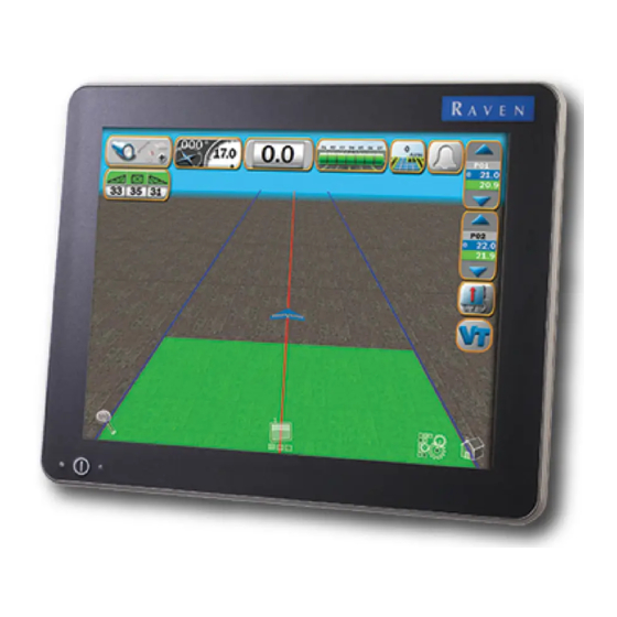
Viper 4 or Viper 4+ field computer. Orientation The Viper 4 and Viper 4+ may be mounted in either a portrait or landscape orientation to best suit field operations, operator needs, or implement cabin space. Raven Viper 4 Field Computer with ROS FIGURE 1. -
Page 29: Mount The Field Computer
The following recommendations are provided to assist with mounting an aerial antenna for use with the Viper 4 or the Viper 4+ integrated receiver. These instructions are not intended to replace instructions provided with any external DGPS equipment. Please refer to, and follow, all mounting and installation instructions for optional or additional DGPS components provided from the equipment manufacturer. - Page 30 Chapter 4 Viper® 4 and Viper 4+ Installation Manual...
-
Page 31: Chapter 5 Viper® 4 And Viper 4+ System Connections
Insert the round, 4-pin connector into the receptacle labeled “1” on the back of the device. Connect the round, 20-pin connector to the receptacle labeled “2.” Disconnect the round connectors from the back of the existing Raven field computer. Connect the adapter cable to the mating harness connectors. -
Page 32: Integrated Dgps Receiver Antenna Cable
Refer to Figure 4 on page 10. Ethernet An ethernet adapter cable is required for the Turck receptacle labeled “3” to connect the Viper 4 or Viper 4+ to a Slingshot Field Hub to receive RTK corrections. Refer to Figure 4 on page 10. - Page 33 Viper® 4 and Viper 4+ System Connections Viper 4+ Cable Connections (D/N 054-5010-010) FIGURE 1. *Kit Suffix Indicates Included Options. Refer to Table on page 20. Antenna Cable Viper 4/Viper 4+ MBA-6 Antenna Aerial Antenna *Mounting Kit Included Mounting Plate...
- Page 34 Chapter 5 Viper® 4 and Viper 4+ Installation Manual...
Need help?
Do you have a question about the Viper 4 and is the answer not in the manual?
Questions and answers