Table of Contents
Advertisement
UM2516
User manual
Electronic speed controller Discovery kit for drones
with STM32G431CB
Introduction
The B-G431B-ESC1 Discovery kit is mainly based on the STM32G431CB microcontroller,
the L6387 driver, and STL180N6F7 power MOSFETs. Its breakable form includes an
electronic speed controller (ESC) board and a daughterboard for user interface with
embedded ST-LINK/V2-1. The ESC has a very compacted size with the goal to drive a
single 3-phase brushless motor (BLDC/PMSM), performing a sensorless field-oriented
control (FOC) or 6-step control with speed regulation and active braking function. This unit
can be connected with an external battery (LiPo type) and accepts a command signal from
an external unit, for instance, a flight control board or similar. The system provides different
communication buses (UART, CAN, PWM) for driving and monitoring, and also embeds an
overcurrent and thermal protection circuit. The daughterboard contains an ST-LINK in-circuit
debugger and programmer, allowing the user to program and debug the STM32G431CB
microcontroller directly with a USB cable using a compatible toolset. Its form factor is
suitable for small and very light R/C vehicles and their motor current capability, and also fits
big vehicle requirements, for instance, a prosumer drone.
.
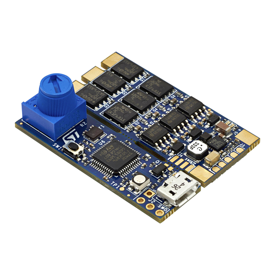
B-G431B-ESC1 Discovery kit
B-G431B-ESC1 Discovery kit
Figure 1.
Figure 2.
(front view)
(bottom view)
Pictures are not contractual.
March 2021
UM2516 Rev 4
1/29
www.st.com
1
Advertisement
Table of Contents

Related Manuals for STMicroelectronics B-G431B-ESC1


Summary of Contents for STMicroelectronics B-G431B-ESC1
-
Page 1: Figure 1. B-G431B-Esc1 Discovery Kit (Front View)
Electronic speed controller Discovery kit for drones with STM32G431CB Introduction The B-G431B-ESC1 Discovery kit is mainly based on the STM32G431CB microcontroller, the L6387 driver, and STL180N6F7 power MOSFETs. Its breakable form includes an electronic speed controller (ESC) board and a daughterboard for user interface with embedded ST-LINK/V2-1. -
Page 2: Table Of Contents
Product marking ..........23 B-G431B-ESC1 product history ....... . 24 7.2.1... - Page 3 UM2516 Contents Appendix A Federal Communications Commission (FCC) and ISED Canada Compliance Statements..... . . 26 FCC Compliance Statement ........26 ISED Compliance Statement.
- Page 4 List of tables UM2516 List of tables Table 1. Ordering information ............7 Table 2.
- Page 5 B-G431B-ESC1 Discovery kit (bottom view)........
-
Page 6: Features
Features UM2516 Features • Full reference design for electronic speed controller capable of both sensorless FOC and 6-step algorithm • Designed for drones with up to 6S LiPo battery pack or equivalent suitable DC supply • 3-phase driver board for BLDC/PMSM motors with discrete N-channel 60 V, 120 A STripFET F7 power MOSFETs ®(a) ®... -
Page 7: Ordering Information
UM2516 Ordering information Ordering information To order the B-G431B-ESC1 Discovery kit, refer to Table 1. Additional information is available from the datasheet and reference manual of the target STM32. Table 1. Ordering information Order code Board reference Target STM32 B-G431B-ESC1... -
Page 8: Development Environment
The source code is available and it is included and generated with this tool. The B-G431B-ESC1 does not have a demonstration firmware preloaded in the STM32 Flash memory, so for the first usage, the user must connect it with the X-CUBE-MCSDK tool. -
Page 9: Description
Description Description The B-G431B-ESC1 Discovery kit is an electronic speed controller (ESC) that drives a single 3-phase brushless motor with very high-performance control. It is commonly used inside the R/C field, for instance, drones, electric cars, and boats, to provide fast and efficient propulsion for the movement. -
Page 10: Figure 4. System Structure Overview
Figure 4. System structure overview The B-G431B-ESC1 provides the maximum flexibility in term of communication protocol (UART, PWM, and CAN are available on-board), and it also contains a DC-DC converter on the daughterboard, with 5 V output connector (BEC) to supply an external board, for instance, a flight control unit or sensors. -
Page 11: Hardware Layout And Configuration
Hardware layout and configuration Hardware layout and configuration Block diagram The B-G431B-ESC1 Discovery kit is a complete hardware platform (power and control) based on several ST products as shown in the following block diagram: Figure 5. Block diagram with ST products The top side is mainly dedicated to the power section. -
Page 12: Figure 7. B-G431B-Esc1 Bottom View
DAC channels (2 external and 2 internal), an internal voltage reference buffer, a low- power RTC, one general-purpose 32-bit timers, two 16-bit PWM timers dedicated to motor control, seven general-purpose 16-bit timers, and one 16-bit low-power timer. Figure 7. B-G431B-ESC1 bottom view 12/29 UM2516 Rev 4... -
Page 13: Board Dimensions
UM2516 Hardware layout and configuration Board dimensions The total dimension of the B-G431B-ESC1 Discovery kit (PCB) is 30 mm x 41 mm as shown Figure Figure 8. B-G431B-ESC1 board mechanical dimensions (top view) UM2516 Rev 4 13/29... -
Page 14: Communication, Programming, And Command Interfaces
Hardware layout and configuration UM2516 Communication, programming, and command interfaces The B-G431B-ESC1 Discovery kit is equipped with a USB connector and different pads for communication, such as: • U4 USB port for programming and debugging • J1 for CAN port •... -
Page 15: Motor Sensor Connection (Hall Or Encoder)
Figure 11 shows that two terminator resistors are needed to open and close the CAN bus line. B-G431B-ESC1 includes this terminator resistor (120 Ω) and it is manageable by firmware (CAN_TERM pin) with a low voltage single-pole-double-throw analog onboard switch (see the CAN page on the electrical schematic). -
Page 16: Stm32G431Cb Pinout For Motor Control
Hardware layout and configuration UM2516 Figure 11. ESC connections with CAN communication Table 3. Truth table 120 Ω resistor CAN_TERM pin 1. High impedance STM32G431CB pinout for motor control Table 4. Main board STM32G431CB pinout for motor control Default Signal Solder Bridge VBAT PC13/TAMP/RTC... - Page 17 UM2516 Hardware layout and configuration Table 4. Main board STM32G431CB pinout for motor control (continued) Default Signal Solder Bridge Curr_fdbk2_OPAmp+ BEMF2 Curr_fdbk3_OPAmp+ Curr_fdbk3_OPAmp- VREF+ VDDA PB10 N.C. VDD4 PB11 BEMF3 PB12 POTENTIOMETER PB13 N.C. PB14 Temperature feedback PB15 TIM1_CH3N STATUS TIM1_CH1 TIM1_CH2 PA10...
-
Page 18: Table 5. Input/Output Terminal Table
Hardware layout and configuration UM2516 Table 5. Input/output terminal table Main I/O Terminal Function J5/J6 LiPo battery power input (3S-6S) 3-phase motor connector 18/29 UM2516 Rev 4... -
Page 19: Connection And First Execution Of The Electronic Speed Controller (Esc)
Connection and first execution of the electronic speed controller (ESC) program Connection and first execution of the electronic speed controller (ESC) program For the correct usage and the first run of the B-G431B-ESC1 Discovery kit, the procedure explained in Section 6.1 Section 6.2 is suggested. -
Page 20: Figure 13. St Mc Workbench Screen
ON. The input connector is composed of two large pads for soldering. The Transil device prevents damage in case of reverse polarity at the input side for a low time. Figure 14. B-G431B-ESC1 I/O connection 20/29 UM2516 Rev 4... -
Page 21: Second Case: Daughterboard Removed
UM2516 Connection and first execution of the electronic speed controller (ESC) program Generate on J3 connector a PWM signal at 490 Hz and duty cycle value between 1060 µs and 1860 µs, the motor starts to rotate respectively from the minimum to the maximum speed. -
Page 22: Figure 16. Swd Configuration On Iar Tool
Connection and first execution of the electronic speed controller (ESC) program UM2516 Figure 16. SWD configuration on IAR tool 22/29 UM2516 Rev 4... -
Page 23: G431B-Esc1 Discovery Kit Information
UM2516 B-G431B-ESC1 Discovery kit information B-G431B-ESC1 Discovery kit information Product marking The stickers located on the top or bottom side of the PCB provide product information: • Product order code and product identification for the first sticker • Board reference with revision, and serial number for the second sticker On the first sticker, the first line provides the product order code, and the second line the product identification. -
Page 24: B-G431B-Esc1 Product History
B-G431B-ESC1 Discovery kit information UM2516 B-G431B-ESC1 product history 7.2.1 Product identification BG431BESC1$AU1 This product identification is based on the mother board MB1419-G431CBU6-B01. It embeds the STM32G431CBU6 microcontroller with silicon revision code "Z". The limitations of this silicon revision are detailed in the errata sheet STM32G431xx/441xx device errata (ES0431). -
Page 25: Board Revision History
UM2516 B-G431B-ESC1 Discovery kit information Board revision history Revision B-01 The revision B-01 of the MB1419 board is the initially released version. Limitations Over lighting of the LD2 LED Revision B-04 The revision B-04 of the MB1419 board removes the limitations of the revision B01 by setting the resistor value of R8 and R9 to 470 Ω. -
Page 26: Appendix A Federal Communications Commission (Fcc) And Ised Canada Compliance Statements
Part 15.21 Any changes or modifications to this equipment not expressly approved by STMicroelectronics may cause harmful interference and void the user’s authority to operate this equipment. Part 15.105 This equipment has been tested and found to comply with the limits for a Class B digital device, pursuant to part 15 of the FCC Rules. -
Page 27: Ised Compliance Statement
UM2516 Federal Communications Commission (FCC) and ISED Canada Compliance Statements ISED Compliance Statement This device complies with FCC and ISED Canada RF radiation exposure limits set forth for general population for mobile application (uncontrolled exposure). This device must not be collocated or operating in conjunction with any other antenna or transmitter. -
Page 28: Revision History
8-Apr-2019 Initial release. Added: 17-Jan-2020 – Section 3.3: Software tool – Recommendation note in Section 6 introduction Added: – Section 7: B-G431B-ESC1 Discovery kit information with updated Product marking, B-G431B-ESC1 product history, and Board revision history 18-Feb-2021 – Class-B Section Appendix A: Federal... - Page 29 IMPORTANT NOTICE – PLEASE READ CAREFULLY STMicroelectronics NV and its subsidiaries (“ST”) reserve the right to make changes, corrections, enhancements, modifications, and improvements to ST products and/or to this document at any time without notice. Purchasers should obtain the latest relevant information on ST products before placing orders.
Need help?
Do you have a question about the B-G431B-ESC1 and is the answer not in the manual?
Questions and answers