Table of Contents
Advertisement
Advertisement
Table of Contents

Subscribe to Our Youtube Channel
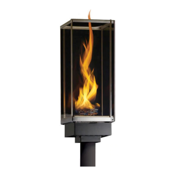
Summary of Contents for Travis Industries Tempest Torch
- Page 1 Copyright © 2019 Travis Industries Certified Factory Training Program...
-
Page 2: Table Of Contents
Page. 1 Contents Power Requirements: ........................... 2 Sequence of Operation: .......................... 2 Trouble Shooting ............................ 4 Torch Wiring Diagram ........................... 7 How To Test Components .......................... 8 Gaining Access To Wires At The Torch Head .................... 8 Testing Continuity Of The Ignitor ...................... 9 Testing Voltage to the Ignitor ........................ 9 Testing Continuity Of The Valve ...................... 10 Testing Voltage to the Valve ........................ 10 Testing The Output Of The Thermopile .................... 11 Wiring Multiple Torches to One Transformer .................... 12 Daisy‐Chain Example .......................... 12 Direct‐Run Example .......................... 12 Daisy‐Chain Wire Length Chart ........................ 13 Replacement Parts ............................ 14 17602099 ‐ 12/9/2019 ... -
Page 3: Power Requirements
Page. 2 Power Requirements: Transformer Minimum Rating 50 volt-amps per torch connected 21VAC - 24VAC minimum 1.6 Amps Minimum 14 Gauge wire. (Refer to the Installation manual for wire gauge requirements.) Sequence of Operation: 1) Call for Ignition (power switch turned on - 110VAC supplied to the transformer). 2) Transformer supplies 24VAC to control module (in the head of the torch). - Page 4 Page. 3 WARNING - *24VAC POWER SUPPLY IS POLARITY SENSITIVE* NOTE: If the torch has had power supplied with the polarity switched, the control modules may be damaged which can result in failure to sense the flame or “cycling”. Often the torch will continue to work once the wiring is corrected.
-
Page 5: Trouble Shooting
Page. 4 Trouble Shooting Trouble shooting will require the torch head be disconnected from its mounting post. Torch does not Light and Igniter does not Glow Red Possible Cause: What to Check: Verify power 24VAC to module Electrical power off ... - Page 6 Page. 5 Torch Lights during Ignition Sequence then goes out during normal operation Possible Cause: What to Check: Verify wiring from transformer to torches is correct. Polarity to Torches not correct Incorrect polarity will damage module Check power output of thermopile. The thermopile is polarity sensitive, check connections and verify proper wiring.
- Page 7 Page. 6 Glass is Sooty Possible Cause: What to Check: Check for spider webs or debris in burner or Blockage in burner Venturi (mixing tube) Wind will influence the flame quality and can cause Windy conditions sooting ...
-
Page 8: Torch Wiring Diagram
Page. 7 Torch Wiring Diagram All wiring inside the torch leads to the control module. The module has remained the same, but the color of the wires from the module has changed. See the two diagrams below. Control Module Wiring Diagram – July 2019 or Later White Red* Black... -
Page 9: How To Test Components
Page. 8 How To Test Components Below you will find details of how to test the individual components of the tempest torch system. This information is for qualified technicians only. Gaining Access To Wires At The Torch Head To test the components of the torch system you will need to gain access to the wires under the torch ... -
Page 10: Testing Continuity Of The Ignitor
Page. 9 Testing Continuity Of The Ignitor Disconnect the two wires from control module (early models – Red/Black and Red/Green – Current models – Red and White/Red) to the ignitor wires (woven white). Set multi meter to read Ohms of resistance (Ω). ... -
Page 11: Testing Continuity Of The Valve
Page. 10 Testing Continuity Of The Valve Disconnect the two wires from control module (early models – Green/Yellow and Green – Current models – Green and White/Green) to the ignitor wires (woven white). Set multi meter to read Ohms of resistance (Ω). ... -
Page 12: Testing The Output Of The Thermopile
Page. 11 Testing The Output Of The Thermopile NOTE: You may need an extra set of hands to help with this test. Someone will need to hold the torch head so that it can be operated. Make sure not to touch hot surfaces. Make sure the two wires from control module (early models – Orange/White and Orange – Current models – Orange and White/Orange) connected to the Thermopile wires (Red and White). -
Page 13: Wiring Multiple Torches To One Transformer
Page. 12 Wiring Multiple Torches to One Transformer The manner in which you wire the torches to the transformer affects the maximum length of wire and wire gauge. Make sure to determine the wire configuration before installation. NOTE: You may use both direct-run and daisy-chain configurations. -
Page 14: Daisy-Chain Wire Length Chart
Page. 13 Daisy-Chain Wire Length Chart This type of wire configuration allows for torches to be wired in a series, reducing the amount of wire used. Use the charts below to determine the correct wire gauge and length. In the example below, the transformer has 3 torches on one branch. -
Page 15: Replacement Parts
BRN SYSTEM ASSY, TMP(EI) LP 250-04609 BRN SYSTEM ASSY, TMP(EI) NG 250-04550 THERMOPILE, TEMPEST 250-04549 IGNITER, TEMPEST 250-01799 THUMB SCREW, TEMPEST TORCH 250-01445 GLASS RETAINER (TEMPEST) 1 EACH 250-01790 FLAME SPREADER w/PYRMD- NG 250-01791 FLAME SPREADER w/PYRMD - LP 250-01256...


Need help?
Do you have a question about the Tempest Torch and is the answer not in the manual?
Questions and answers