Advertisement
Quick Links
Instruction Manual
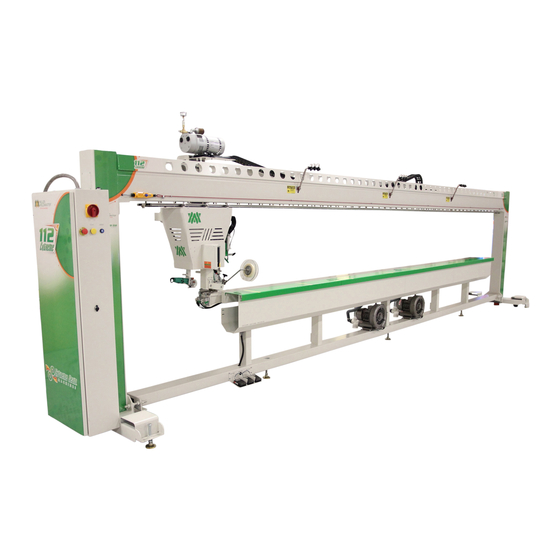
This instruction manual is intended to be a guide when operating the 112 Extreme Seam welder. To
ensure optimal performance from your welder, please follow the recommendations and specifications
precisely.
For more technical information regarding this machine call our Resolution Center at 1-855-888-WELD or
email service@weldmaster.com.
You can also subscribe to Miller Weldmaster Insiders to stay updated on tech tips, machine maintenance
updates, and more at www.weldmaster.com/insiders.
330.833.6739
www.weldmaster.com
Page 1
Advertisement

Related Manuals for Miller Weldmaster 112 Extreme


Summary of Contents for Miller Weldmaster 112 Extreme
- Page 1 Instruction Manual This instruction manual is intended to be a guide when operating the 112 Extreme Seam welder. To ensure optimal performance from your welder, please follow the recommendations and specifications precisely. For more technical information regarding this machine call our Resolution Center at 1-855-888-WELD or email service@weldmaster.com.
- Page 2 Instruction Manual Table of Contents Chapter 1: Intended Use Page 3 Chapter 2: Explanation of Warnings Pages 4-5 Chapter 3: Electrical and Air Requirements Page 6 Chapter 4: Principals of Heat Sealing Page 7 Chapter 5: Screen Shots Pages 7-13 Chapter 6: Adjustments Pages 14-24 Chapter 7: Maintenance...
-
Page 3: Chapter 1 Intended Use
Instruction Manual Intended Use The 112 is a rotary hot air welding machine intended to heat-seal weldable thermal plastics such as: • Non-woven polypropylene • Vinyl (PVC) laminated fabrics • Vinyl (PVC) coated fabrics • Vinyl (PVC) films • Polyurethane (PU) coated fabrics •... -
Page 4: Chapter 2 Explanation Of Warnings
Instruction Manual Explanation of Warnings There are several different warning symbols placed on the Miller Weldmaster 112. The symbols are to alert the operator of potentially hazardous areas on the machine. Familiarize yourself with their placement and meaning. Caution: Hot The “Caution: Hot”... - Page 5 Instruction Manual Explanation of Warnings Warning: Keep Hands Clear The“Warning: Keep Hands Clear” sticker is placed on the Heater Assembly. To prevent any pinching or burns, be aware of the location of your hands at all times. Warning: High Temperature Air The “Warning: High Temperature Air”...
- Page 6 •60 Amperes - 3 phases - 400 Volts Shop Air Supply The Miller Weldmaster 112 Extreme includes an In-Shop Air Supply Valve that allows quick connects and disconnects to your shop air supply. Due to the number of different style airline connectors, a male quick-connect is not included.
- Page 7 Instruction Manual Principals of Heat Sealing Hot Air The heat required for the welding operation is created electrically by two heating element locat- ed inside the heat element housing. The hot air temperature ranges from 100 to 1350 Degrees Fahrenheit or 25 to 730 Degrees Celsius. Speed The Speed of the Weld Rollers determines the amount of time the heat is applied to the material being welded.
- Page 8 Weld Roller: The purpose of this function is to lift the weld roller up or down. Machine Speed: The purpose of Machine Speed is to control the speed of the carriage assembly during the welding process. The machine speed number is a percentage of how fast the 112 extreme head carriage will run.
- Page 9 Instruction Manual Screen Shots Control: Pressing this button opens the Control screen. Welding Head: Pressing this button opens the welding head screen. Main Menu: Pressing this button opens the main menu screen. Heat 1: Pressing this button, opens up the controls for each welding head. Recipe Active Screen: Displays all the current parameters for the selected recipe.
- Page 10 Laser-Butt: The purpose of this button is when depressed, it will turn green and turn on the butt laser and turn off the overlap laser. Weld/Cut: In this box, if weld is showing, the 112 extreme is in the weld mode. By touching the box it will switch the mode to cut and the 112 will be in the cut mode.
- Page 11 Instruction Manual Screen Shots Heat 1: Pressing this button, opens up the controls for the selected welding head. Alarms: This displays the current active alarms if any. Recipe Active screen: Displays all the current parameters for the selected recipe. Recipe Edit: Pressing this button opens up the Recipe Edit screen. Info: Pressing this button will take you to the information screen.
- Page 12 Instruction Manual Screen Shots Temperature SP: The purpose of this box is to show the set point for the temperature and also allow the operator to manually change the temperature without going into the recipes. Temperature PV: The purpose of this box is to show the operator what the actual temperature is reading at the elements.
- Page 13 Instruction Manual Screen Shots Recipe #: The number of the current recipe. Recipe Name: The name of the current recipe. Weld Unit #: This is the temperature set point we are setting each welding head at. Speed %: Controls the overall machine speed. This is the master speed control. Clutch Pressure: The purpose of Clutch Pressure is to vary the amount of drive force on the weld roller.
- Page 14 Instruction Manual Adjustments Nozzle Adjustment Nozzle placement is a key component in heat sealing. A properly-placed nozzle will be centered on the weld roller approximately ¼-inch away and have a slight whistle during the welding process. When an adjustment is needed, turn the speed control to a low setting. Make the adjustment and check the nozzle placement by engaging the Start Switch.
-
Page 15: Chapter 6 Recommended Replacement Parts
Instruction Manual Adjustments Warning! When adjusting the lasers, do not look directly into the laser source. Use caution when calibrating lasers. Laser Alignment Double Laser Line 1.Turn the POWER on. 2. Leave the Heat Switch in the OFF position. Load some sample fabric (white is best) under the fabric clamp and extend to the end of the machine. - Page 16 Instruction Manual Adjustments Guide Adjustments Welding a Hem: The hem guide needs to be 1/16 to 1/8inch off track and aligned perpendicular to track. The outside of guide needs to be adjusted to outside of weld roller. After running a test if there is a pocket on the hem move guide away from operator.
- Page 17 Instruction Manual Adjustments Welding a Hem with Rope: Welding a hem with rope is the same as welding a straight hem except you are adding rope through the rope eyelet or leaving a void for the open pocket. 1. Install hem and rope guide. 2.
- Page 18 Instruction Manual Adjustments Welding an Overlap •The overlap guide needs to be high enough so the nozzle can swing in and not hit the bottom of the guide. The guide also needs to be perpendicular to the track. •The overlap guide is used to control the exact positioning of the top fabric panel being welded.
- Page 19 Instruction Manual Adjustments Welding a Pole Pocket •The pocket guide needs to be high enough so the nozzle does not hit the bottom of the guide. It also needs to be perpendicular to the track. •The pocket guide is used to weld pole pockets. The guide is used to control the exact positioning of the top flap of material.
- Page 20 Instruction Manual Adjustments Welding Webbings or Tapes 1. Install the adjustable webbing or tape guide to the machine. 2. Adjust the guide to the correct width of your webbing or tape. 3. Insure that the weld roller and nozzle will not touch the guide. The guide also needs adjusted parallel to the wheel.
- Page 21 Instruction Manual Adjustments Interchanging of Weld Rollers 1. Loosen the bolt on the weld roller clamping collar. 2. Slide the weld roller off of the weld roller shaft. 3. Slide the new weld roller on to the weld roller shaft. a.
- Page 22 Instruction Manual Adjustments Weld Roller Cylinder Adjustment •The pressure on the weld roller is created from the pneumatic cylinder used to pick up or put down the weld roller. •The pressure on the weld roller is regulated and displayed on the control panel. The pressure needs to be set at least at 10lbs.
- Page 23 Adjustments Micro-Switch Adjustments This page will detail each of the Micro-switches and sensors on the Miller Weldmaster 112 Extreme. •Overrun Limit Switch: The purpose of this switch is to stop the head carriage from over travel. *Note: This switch will initiate the Emergency Stop and take power and air from the machine.
-
Page 24: Maintenance
Maintenance •Air Filter Cartridge: The Miller Weldmaster 112 Extreme has an Air Compressor that supplies airflow to the heat elements. Periodic cleaning and changing of the Air Filter Cartridge is necessary to maintain sufficient airflow. Insufficient airflow or any impurities in the airflow will shorten the life of the heat elements. - Page 25 Instruction Manual Maintenance Page 25 CHAPTER 7 ADJUSTMENTS...
- Page 26 +/- 2 Degrees F (+/- 1 Degree C) or the heat elements burn out prematurely. Warning! Only a qualified technician may perform maintenance on this machine. This may be a Miller Weldmaster representative or someone trained by a Miller Weldmaster representative.
- Page 27 Instruction Manual Maintenance 5. Remove thermocouple wire mounts. 6. Remove the bottom cover and some of the fiberglass insulation from the element housing. 7. Using an 7/16 wrench, carefully loosen 8. Install the new thermocouple with all the and remove the thermocouple nut. spacers in the sequence shown.
- Page 28 Instruction Manual Maintenance 11. Install both thermocouple wire mounts. 12. Install the nozzle and clamp. Make certain to install the clamp with the grooved side up. 13. Plug in the thermocouple leads. If the temperature starts reading backwards, flip the leads. CHAPTER 8 MAINTENANCE Page 28...
- Page 29 Changing the Heat Elements The heating elements used by the Miller Weldmaster machine are rated for 1000 hours of use at 1000 degrees F (537 degrees C). Although longer heat element life is possible with proper maintenance, 1000 hours is the average.
- Page 30 Instruction Manual Maintenance 5.Remove the top covering of the element 6. Remove the 2 pieces of insulation between housing and slide it out of the way. the wire leads and the aluminum air divider. 7. Remove the 4 leads from the heat 8.
-
Page 31: Chapter 10 Troubleshooting
Instruction Manual Maintenance 11. Carefully install 2 new heat elements 12. Install the aluminum air divider. into the dual element housing. 13. Connect the four wire leads to the elements. 14. Inset the 2 pieces of insulation be- Make sure wires #1 and #3 plug onto one tween the wires and the aluminum air element, and wires #2 and #4 plug onto the other element. - Page 32 Instruction Manual Troubleshooting NOTE: The machine must have at least 90psi of air pressure in order to Reset power. Loss of Welding Temperature -Heat elements may be burned out, check number of hours on the heat elements. The heat elements are rated for 1000 hours at 730C. -Thermocouple may be burned out or loose wires.
- Page 33 Instruction Manual Troubleshooting Seam is Only Welded on One Side •The hot air nozzle tip needs to be adjusted. -Nozzle needs adjusted side to side. -Nozzle may be pinched shut on one side. Open the pinched side so there is even flow. -The speed control is set too high not allowing enough time for the hot air to be applied to the seam properly.
- Page 34 Instruction Manual Troubleshooting •Hem is over puckering or burnt one side out. -Temperature is too hot. Turn heat down or speed up the machine. •Hem will not stay in guide. -Guide not square, adjust guide. -Add clutch pressure. •Nozzle hits material. -Nozzle too high.
- Page 35 Instruction Manual Troubleshooting Butt Seam •Tape not centered in weld. -Guide misaligned. -Center of butt not aligned with laser. -Laser line not centered with weld roller. •Tape wrinkling. -Too much clutch pressure. -Too hot. Truck Side Beading •Indicator line does not line up with material. -Guide misaligned.
- Page 36 Instruction Manual NOTES:_________________________________________________________________ _______________________________________________________________________ _______________________________________________________________________ _______________________________________________________________________ _______________________________________________________________________ _______________________________________________________________________ _______________________________________________________________________ _______________________________________________________________________ _______________________________________________________________________ ______________________________________________________________________ _______________________________________________________________________ _______________________________________________________________________ _______________________________________________________________________ _______________________________________________________________________ _______________________________________________________________________ _______________________________________________________________________ Page 36...
- Page 37 Instruction Manual NOTES:_________________________________________________________________ _______________________________________________________________________ _______________________________________________________________________ _______________________________________________________________________ _______________________________________________________________________ _______________________________________________________________________ _______________________________________________________________________ _______________________________________________________________________ _______________________________________________________________________ ______________________________________________________________________ _______________________________________________________________________ _______________________________________________________________________ _______________________________________________________________________ _______________________________________________________________________ _______________________________________________________________________ _______________________________________________________________________ Page 37...
Need help?
Do you have a question about the 112 Extreme and is the answer not in the manual?
Questions and answers