Vega VEGABAR 81 Operating Instructions Manual
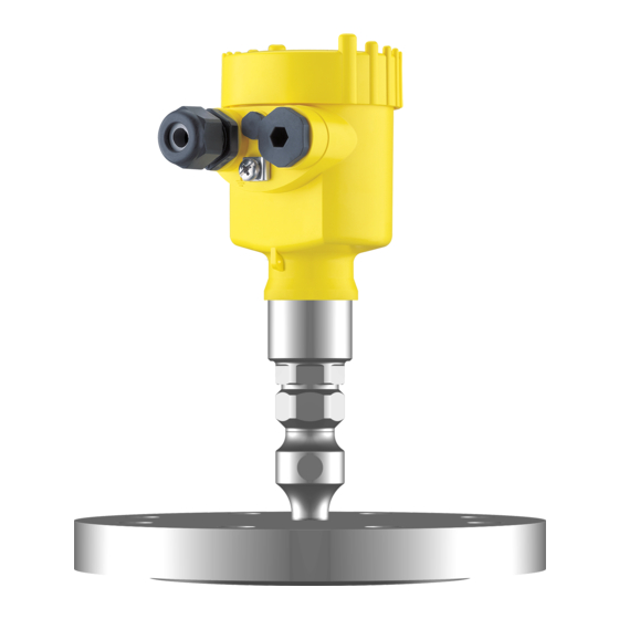
Pressure transmitter with chemical seal foundation fieldbus
Hide thumbs
Also See for VEGABAR 81:
- Operating instructions manual (96 pages) ,
- Quick setup manual (20 pages) ,
- Product information (16 pages)

Related Manuals for Vega VEGABAR 81


Summary of Contents for Vega VEGABAR 81
- Page 1 Operating Instructions Pressure transmitter with chemical seal VEGABAR 81 Foundation Fieldbus Document ID: 45021...
-
Page 2: Table Of Contents
Parameter adjustment - Quick setup ................32 Parameter adjustment - Extended adjustment..............32 Saving the parameterisation data ................... 44 Setup with PACTware ......................45 Connect the PC ......................45 Parameter adjustment with PACTware ................45 Saving the parameterisation data ................... 46 VEGABAR 81 • Foundation Fieldbus... - Page 3 11.5 Industrial property rights ....................79 11.6 Trademark ........................79 Safety instructions for Ex areas Take note of the Ex specific safety instructions for Ex applications. These instructions are attached as documents to each instrument with Ex approval and are part of the operating instructions. Editing status: 2020-05-12 VEGABAR 81 • Foundation Fieldbus...
-
Page 4: About This Document
Symbols used Document ID This symbol on the front page of this instruction refers to the Docu- ment ID. By entering the Document ID on www.vega.com you will reach the document download. Information, note, tip: This symbol indicates helpful additional infor- mation and tips for successful work. -
Page 5: For Your Safety
During work on and with the device, the required personal protective equipment must always be worn. Appropriate use The VEGABAR 81 is a pressure transmitter for process pressure and hydrostatic level measurement. You can find detailed information about the area of application in chapter "Product description". Operational reliability is ensured only if the instrument is properly used according to the specifications in the operating instructions manual as well as possible supplementary instructions. -
Page 6: Namur Recommendations
DIN EN ISO 14001. Please help us fulfil this obligation by observing the environmental instructions in this manual: • Chapter "Packaging, transport and storage" • Chapter "Disposal" Exception: Versions with measuring ranges from 250 bar. These are subject of the EU Pressure Device Directive. VEGABAR 81 • Foundation Fieldbus... -
Page 7: Product Description
The scope of delivery encompasses: • VEGABAR 81 pressure transmitter The further scope of delivery encompasses: • Documentation – Quick setup guide VEGABAR 81 – Test certificate for pressure transmitters – Instructions for optional instrument features – Ex-specific "Safety instructions" (with Ex versions) – If necessary, further certificates Information: Optional instrument features are also described in this operating instructions manual. -
Page 8: Principle Of Operation
Scan the DataMatrix code on the type label of the instrument or • Enter the serial number manually in the app Principle of operation Application area VEGABAR 81 is suitable for applications in virtually all industries. It is used for the measurement of the following pressure types. • Gauge pressure •... - Page 9 Fig. 3: Electronic differential pressure measurement through Master/Slave combination You can find detailed information in the operating instructions of the respective slave sensor. The VEGABAR 81 is equipped with a chemical seal. It consists of a Chemical seal stainless steel diaphragm and a transmission liquid. A chemical seal has two tasks: •...
- Page 10 The ambient pressure is detected in the measuring cell and compen- sated. It thus has no influence on the measured value. Absolute pressure: the measuring cell contains vacuum and is encapsulated. The ambient pressure is not compensated and does hence influence the measured value. Seal concept The measuring system is completely welded and thus sealed against the process. VEGABAR 81 • Foundation Fieldbus...
-
Page 11: Packaging, Transport And Storage
The integrated Bluetooth module (optional) enables wireless adjust- ment via standard adjustment devices. The interface adapter VEGACONNECT enables the connection of VEGACONNECT communication-capable instruments to the USB interface of a PC. VEGABAR 81 • Foundation Fieldbus... - Page 12 3 Product description Slave sensors of VEGABAR series 80 enable in conjunction with Slave sensors VEGABAR 81 an electronic differential pressure measurement. VEGADIS 81 The VEGADIS 81 is an external display and adjustment unit for VEGA plics sensors. ® VEGADIS adapter The VEGADIS adapter is an accessory part for sensors with double chamber housings.
-
Page 13: Mounting
To maintain the housing protection, make sure that the housing lid is closed during operation and locked, if necessary. Screwing in Devices with threaded fitting are screwed into the process fitting with a suitable wrench via the hexagon. See chapter "Dimensions" for wrench size. VEGABAR 81 • Foundation Fieldbus... - Page 14 Make sure that the upper temperature limits stated in chapter "Technical data" for the environment of the electronics hous- ing and connection cable are not exceeded. Fig. 7: Temperature ranges Process temperature Ambient temperature VEGABAR 81 • Foundation Fieldbus...
-
Page 15: Instructions For Oxygen Applications
When quickly opening/closing the housing cover, the measured value can change for approx. 5 s by up to 15 mbar. For an effective ventilation, the filter element must be always free from buildup. In case of horizontal mounting, turn the housing so that the filter element points downward after the instrument is installed. This provides better protection against buildup. Caution: Do not use a high-pressure cleaner. The filter element could be dam- aged, which would allow moisture into the housing. The following paragraphs describe how the filter element is arranged in the different instrument versions. VEGABAR 81 • Foundation Fieldbus... - Page 16 This provides better protection against buildup. Fig. 9: Position of the filter element - Ex-d version Rotatable metal ring Filter element Instruments with absolute pressure have a blind plug mounted instead of the filter element. VEGABAR 81 • Foundation Fieldbus...
-
Page 17: Process Pressure Measurement
Instruments with absolute pressure have a blind plug mounted instead of the filter element. Process pressure measurement Measurement setup in Keep the following in mind when setting up the measuring system: gases • Mount the instrument above the measuring point Possible condensation can then drain off into the process line. VEGABAR 81 • Foundation Fieldbus... - Page 18 Siphon in U or circular form Pipeline A protective accumulation of water is formed through condensation in the pipe bends. Even in applications with hot steam, a medium temperature < 100 °C on the transmitter is ensured. VEGABAR 81 • Foundation Fieldbus...
-
Page 19: Level Measurement
Keep the following in mind when setting up the measuring system: • Mount the instrument below the min. level • Do not mount the instrument close to the filling stream or emptying area • Mount the instrument so that it is protected against pressure shocks from the stirrer Fig. 15: Measurement setup for the level measurement VEGABAR 81 • Foundation Fieldbus... -
Page 20: External Housing
4 Mounting External housing Configuration Fig. 16: Configuration, process module, external housing Pipeline Process module Connection cable process assembly - External housing External housing Signal cable VEGABAR 81 • Foundation Fieldbus... -
Page 21: Connecting To The Bus System
In the case of instrument housings with self-sealing NPT threads, it is not possible to have the cable entries screwed in at the factory. The free openings for the cable glands are therefore covered with red dust protection caps as transport protection. VEGABAR 81 • Foundation Fieldbus... -
Page 22: Connecting
6. Insert the wire ends into the terminals according to the wiring plan Note: Solid cores as well as flexible cores with wire end sleeves are insert- ed directly into the terminal openings. In case of flexible cores without end sleeves, press the terminal from above with a small screwdriver, the terminal opening is then free. When the screwdriver is released, the terminal closes again. VEGABAR 81 • Foundation Fieldbus... -
Page 23: Single Chamber Housing
Simulation switch ("1" = mode for simulation release) For external display and adjustment unit Ground terminal for connection of the cable screening Double chamber housing The following illustrations apply to the non-Ex as well as to the Ex-ia version. VEGABAR 81 • Foundation Fieldbus... - Page 24 6 7 8 Fig. 20: Connection compartment - double chamber housing Voltage supply, signal output For display and adjustment module or interface adapter For external display and adjustment unit Ground terminal for connection of the cable screening VEGABAR 81 • Foundation Fieldbus...
-
Page 25: Double Chamber Housing With Vegadis-Adapter
Fig. 22: View to the plug connector M12 x 1 Pin 1 Pin 2 Pin 3 Pin 4 Contact pin Colour, connection ca- Terminal, electronics ble in the sensor module Pin 1 Brown Pin 2 White Pin 3 Blue Pin 4 Black VEGABAR 81 • Foundation Fieldbus... -
Page 26: Housing Ip66/Ip68 (1 Bar)
Brown (+) and blue (-) to power supply or to the processing system Shielding External housing with version IP68 (25 bar) Overview Fig. 24: VEGABAR 81 in IP68 version 25 bar with axial cable outlet, external housing Transmitter Connection cable External housing VEGABAR 81 •... - Page 27 Cable gland for voltage supply Cable gland for connection cable, transmitter Terminal compartment, housing socket 1 2 3 4 Fig. 26: Connection of the process component in the housing base Yellow White Black Shielding Breather capillaries VEGABAR 81 • Foundation Fieldbus...
-
Page 28: Switch-On Phase
Indication of a status message on the display or PC Then the actual measured value is output to the signal cable. The value takes into account settings that have already been carried out, e.g. default setting. VEGABAR 81 • Foundation Fieldbus... -
Page 29: Set Up With The Display And Adjustment Module
The display and adjustment module is powered by the sensor, an ad- ditional connection is not necessary. Fig. 28: Installing the display and adjustment module in the electronics compart- ment of the single chamber housing VEGABAR 81 • Foundation Fieldbus... -
Page 30: Adjustment System
– Move to the menu overview – Confirm selected menu – Edit parameter – Save value • [->] key: – Change measured value presentation – Select list entry – Select menu items – Select editing position • [+] key: VEGABAR 81 • Foundation Fieldbus... -
Page 31: Measured Value Indication
[OK] will not be saved. Measured value indication Measured value indica- With the [->] key you can move between three different indication tion modes. In the first view, the selected measured value is displayed in large digits. In the second view, the selected measured value and a correspond- ing bargraph presentation are displayed. VEGABAR 81 • Foundation Fieldbus... -
Page 32: Parameter Adjustment - Quick Setup
[->] or [ESC] keys or automatically after 3 s Note: You can find a description of the individual steps in the quick setup guide of the sensor. You can find "Extended adjustment" in the next sub-chapter. Parameter adjustment - Extended adjustment For technically demanding measuring points, you can carry out extended settings in "Extended adjustment". VEGABAR 81 • Foundation Fieldbus... - Page 33 Application In this menu item you activate/deactivate the slave sensor for elec- tronic differential pressure and select the application. VEGABAR 81 can be used for process pressure and level measure- ment. Default setting is process pressure measurement. The mode can be changed in this adjustment menu.
- Page 34 20 % of the nominal measuring range, then no position correction is possible. Adjustment VEGABAR 81 always measures pressure independently of the pro- cess variable selected in the menu item "Application". To output the VEGABAR 81 • Foundation Fieldbus...
- Page 35 1. Select the menu item "Setup" with [->] and confirm with [OK]. Now select with [->] the menu item "Zero adjustment" and confirm with [OK]. 2. Edit the mbar value with [OK] and set the cursor to the requested position with [->]. VEGABAR 81 • Foundation Fieldbus...
- Page 36 [OK]. The span adjustment is finished. Min. adjustment level Proceed as follows: 1. Select the menu item "Setup" with [->] and confirm with [OK]. Now select with [->] the menu item "Adjustment", then "Min. adjustment" and confirm with [OK]. VEGABAR 81 • Foundation Fieldbus...
- Page 37 Linearisation A linearization is necessary for all vessels in which the vessel volume does not increase linearly with the level - e.g. a horizontal cylindri- cal or spherical tank - and the indication or output of the volume is required. Corresponding linearization curves are preprogrammed for these vessels. They represent the correlation between the level per- centage and vessel volume. The linearization applies to the measured value indication and the current output. VEGABAR 81 • Foundation Fieldbus...
- Page 38 This menu item enables the setting of the requested national lan- guage. The following languages are available: • German • English • French • Spanish • Russian • Italian • Dutch • Portuguese • Japanese • Chinese • Polish VEGABAR 81 • Foundation Fieldbus...
- Page 39 6 Set up with the display and adjustment module • Czech • Turkish In delivery status, the VEGABAR 81 is set to English. Display value 1 and 2 In this menu item, you define which measured value is displayed. The default setting for the display value is "Lin. percent". Display format 1 and 2 In this menu item you define the number of decimal positions with which the measured value is displayed.
- Page 40 In this menu item, you adjust the internal clock of the sensor. There is no adjustment for summer/winter (daylight saving) time. Reset After a reset, certain parameter adjustments made by the user are reset. The following reset functions are available: VEGABAR 81 • Foundation Fieldbus...
- Page 41 Ceramic measuring cell: Measuring cell temperature in °C Metallic measuring cell: Electronics temperature in °C Display format 1 and 2 Number of positions after the decimal point, automatically Backlight Switched on Diagnostics Menu item Parameter Default value Sensor status VEGABAR 81 • Foundation Fieldbus...
- Page 42 The data are saved only after release. Special parameters In this menu item you gain access to the protected area where you can enter special parameters. In exceptional cases, individual VEGABAR 81 • Foundation Fieldbus...
- Page 43 PC. Device ID In this menu item, the identification number of the instrument in a Foundation Fieldbus system is shown. Sensor characteristics In this menu item, the features of the sensor such as approval, pro- cess fitting, seal, measuring range, electronics, housing and others are displayed. VEGABAR 81 • Foundation Fieldbus...
-
Page 44: Saving The Parameterisation Data
In the display and adjust- If the instrument is equipped with a display and adjustment module, ment module the parameter adjustment data can be saved therein. The procedure is described in menu item "Copy device settings". VEGABAR 81 • Foundation Fieldbus... -
Page 45: Setup With Pactware
Further setup steps are described in the operating instructions manu- al "DTM Collection/PACTware" attached to each DTM Collection and which can also be downloaded from the Internet. Detailed descrip- tions are available in the online help of PACTware and the DTMs. VEGABAR 81 • Foundation Fieldbus... -
Page 46: Saving The Parameterisation Data
The standard version is available as a download under www.vega.com/downloads and "Software". The full version is avail- able on CD from the agency serving you. Saving the parameterisation data We recommend documenting or saving the parameterisation data via PACTware. -
Page 47: Set Up With Other Systems
8 Set up with other systems Set up with other systems DD adjustment programs Device descriptions as Enhanced Device Description (EDD) are available for DD adjustment programs such as, for example, AMS↑ and PDM. The files can be downloaded at www.vega.com/downloads under "Software". VEGABAR 81 • Foundation Fieldbus... -
Page 48: Diagnosis, Asset Management And Service
Event memory Up to 500 events are automatically stored with a time stamp in the sensor (non-deletable). Each entry contains date/time, event type, event description and value. Event types are for example: • Modification of a parameter VEGABAR 81 • Foundation Fieldbus... -
Page 49: Asset Management Function
This status message is inactive by default. Maintenance required: Due to external influences, the instrument function is limited. The measurement is affected, but the measured value is still valid. Plan in maintenance for the instrument because a failure is expected in the near future (e.g. due to buildup). This status message is inactive by default. VEGABAR 81 • Foundation Fieldbus... - Page 50 Repeat reset settings F264 Inconsistent settings (e.g.: dis- Modify settings Bit 10 tance, adjustment units with Installation/Setup error Modify connected sensor config- application process pressure) for uration or application selected application Invalid sensor configuration (e.g.: application electronic differential pressure with connected differen- tial pressure measuring cell) VEGABAR 81 • Foundation Fieldbus...
- Page 51 Hardware error EEPROM Exchanging the electronics Bit 17 Error in the event Send instrument for repair memory M504 Hardware defect Exchanging the electronics Bit 19 Error at a device in- Send instrument for repair terface VEGABAR 81 • Foundation Fieldbus...
-
Page 52: Rectify Faults
24 hour service hotline Should these measures not be successful, please call in urgent cases the VEGA service hotline under the phone no. +49 1805 858550. The hotline is also available outside normal working hours, seven days a week around the clock. -
Page 53: Software Update
Proceed as follows when carrying out the exchange: 1. Losen the fixing screw with the hexagon key wrench 2. Carefully detach the cable assembly from the process module Fig. 36: VEGABAR 81 in IP68 version, 25 bar and lateral cable outlet, external housing Process module Plug connector... -
Page 54: How To Proceed If A Repair Is Necessary
Clean the instrument and pack it damage-proof • Attach the completed form and, if need be, also a safety data sheet outside on the packaging • Ask the agency serving you to get the address for the return ship- ment. You can find the agency on our homepage. VEGABAR 81 • Foundation Fieldbus... -
Page 55: Dismount
Pass the instrument directly on to a specialised recycling company and do not use the municipal collecting points. If you have no way to dispose of the old instrument properly, please contact us concerning return and disposal. VEGABAR 81 • Foundation Fieldbus... -
Page 56: Supplement
Glass with Aluminium and stainless steel precision casting and Ex d housing Only for 316L with 3A approval Glass with Aluminium and stainless steel precision casting housing Between transmitter and external electronics housing. VEGABAR 81 • Foundation Fieldbus... - Page 57 -1 … 0 bar/-100 … 0 kPa +3 bar/+300 kPa -1 bar/-100 kPa -1 … +1.5 bar/-100 … +150 kPa +7.5 bar/+750 kPa -1 bar/-100 kPa Fix connected to the sensor. Data on overload capability apply for reference temperature. VEGABAR 81 • Foundation Fieldbus...
- Page 58 Output signal digital output signal, Foundation Fieldbus protocol Transmission rate 31.25 Kbit/s Damping (63 % of the input variable) 0 … 999 s, adjustable Channel Numbers Ʋ Channel 1 Process value Ʋ Channel 8 Electronics temperature VEGABAR 81 • Foundation Fieldbus...
- Page 59 Fig. 37: Sudden change of the process variable. t : dead time; t : rise time; t : jump response time Process variable Output signal VEGABAR 81 VEGABAR 81 - IP68 (25 bar) Dead time ≤ 25 ms ≤ 50 ms Rise time (10 … 90 %) ≤ 55 ms ≤ 150 ms Step response time (ti: 0 s, 10 …...
- Page 60 Ʋ Flange 3" 150 lbs RF, ASME B16.5 1.34 mbar/10 K with extension 2" Temperature coefficient of a cooling ele- 0.1 … 1.5 mbar/10 K ment, depending on the diaphragm-ø Temperature coefficient of a 1 m 0.1 … 15 mbar/10 K long capillary line, depending on the diaphragm-ø VEGABAR 81 • Foundation Fieldbus...
- Page 61 Neobee KN 59 -20 … +150 °C (+14 … +302 °F) Process pressure Permissible process pressure see specification "process pressure" on the type label. Permissible process pressure for fittings PN 160 in Alloy 400 (2.4360), see following temperature derating: Depending on which chemical seal is used, the values can also be higher. no vacuum VEGABAR 81 • Foundation Fieldbus...
- Page 62 50 °C 100 °C 150 °C (-104 °F) (122 °F) (212 °F) (302 °F) Fig. 38: Temperature derating VEGABAR 81, process fittings Alloy 400 (2.4360) Process temperature Process pressure Mechanical stress Vibration resistance Ʋ Standard versions 1 to 4 g at 5 … 200 Hz according to EN 60068-2-6 (vibration with resonance) Ʋ...
- Page 63 Standard cable Shielded 4 … 20 mA/HART 50 m ● – Modbus Profibus PA, Foundation Fieldbus 25 m – ● Interface to the slave sensor Data transmission Digital (I²C-Bus) Configuration, connection cable 4-wire, shielded Breather capillaries not with Ex-d version. VEGABAR 81 • Foundation Fieldbus...
- Page 64 Double chamber IP66/IP67 Type 4X IP66/IP68 (0.2 bar) Type 6P Stainless steel (electro-polished) Single chamber IP66/IP67 Type 4X IP69K Galvanic separation between electronics and metal housing parts Protection rating IP66/IP68 (0.2 bar) only in conjunction with absolute pressure. VEGABAR 81 • Foundation Fieldbus...
-
Page 65: Chemical Seal With Vacuum Applications
For that reason, chemical seal systems can only be used to a limited extent in a vacuum, depending on the pressure transmission liquid, process temperature and pressure. To extend the area of ap- plication, we offer a so-called vacuum service as an option. The following graphics show the areas of application for the different pressure transmission liquids. When used with fulfilled housing protection. VEGABAR 81 • Foundation Fieldbus... - Page 66 Fig. 39: Area of application for silicone oil VE 2, KN 2 Standard chemical seal Chemical seal with vacuum service mbar 1000 -100 T °C Fig. 40: Area of application for silicone oil KN 17 Standard chemical seal Chemical seal with vacuum service VEGABAR 81 • Foundation Fieldbus...
- Page 67 Fig. 41: Area of application for high temperature oil VE 32, KN 32 Standard chemical seal Chemical seal with vacuum service mbar 1000 -100 T °C Fig. 42: Area of application for Halocarbon oil KN 21 Standard chemical seal Chemical seal with vacuum service VEGABAR 81 • Foundation Fieldbus...
- Page 68 Fig. 43: Area of application for med. white oil VE 92, KN 92 Standard chemical seal Chemical seal with vacuum service mbar 1000 -100 T °C Fig. 44: Area of application for vegetable oil KN 59 Standard chemical seal Chemical seal with vacuum service VEGABAR 81 • Foundation Fieldbus...
-
Page 69: Device Communication Foundation Fieldbus
Transducer Block (TB) Standard Block (AI) Execution Time 30 mS Advanced Function Blocks Discret Input (DI) PID Control Output Splitter (OS) Signal Characterizer (SC) Integrator Input Selector (IS) Arithmetic (AR) Diagnostics Standard Advanced Performance Function Blocks Instantiable VEGABAR 81 • Foundation Fieldbus... -
Page 70: Dimensions
Number of VCRs (Virtual Communication Re- lationships) 11.4 Dimensions The following dimensional drawings represent only an extract of the possible versions. Detailed dimensional drawings can be downloaded at www.vega.com under "Downloads" and "Drawings". Plastic housing ~ 69 mm ~ 84 mm (2.72") - Page 71 Fig. 48: Housing versions in protection rating IP66/IP68 (0.2 bar), (with integrated display and adjustment module the housing is 9 mm/0.35 in or 18 mm/0.71 in higher) Stainless steel single chamber (electropolished) Stainless steel single chamber (precision casting) Stainless steel double chamber housing (precision casting) VEGABAR 81 • Foundation Fieldbus...
- Page 72 ~ 59 mm (2.3") ø 80 mm (3.15") M20x1,5/ ½ NPT Fig. 50: Housing version with protection rating IP69K (with integrated display and adjustment module the housing is 9 mm/0.35 in higher) Stainless steel single chamber (electropolished) VEGABAR 81 • Foundation Fieldbus...
- Page 73 8 mm (0.12") (0.32") 110 mm x 90 mm (4.33" x 3.54") Fig. 51: VEGABAR 81, IP68 version with external housing Lateral cable outlet Axial cable outlet Plastic single chamber Stainless steel single chamber Seal 2 mm (0.079 in), (only with 3A approval)
- Page 74 (1.54") ø 60 mm (2.36") Fig. 52: VEGABAR 81, threaded fitting GE G½ A outside PN 160, ISO 228-1; diaphragm: inside; > 105 °C with temperature adapter GK G¾ A outside PN 600, DIN 3852-E; diaphragm: front-flush GL G1 A outside PN 600, ISO 228-1; diaphragm: front-flush GN G1½...
- Page 75 RD44x " inch RD44x " 4.09" 0.79" Fig. 53: VEGABAR 81, tube isolating diaphragm Tube isolating diaphragm for mounting between flanges Tube isolating diaphragm according to DIN 11851 Tube isolating diaphragm according to DIN 11864-1 VEGABAR 81 • Foundation Fieldbus...
- Page 76 120,7 4 x ø20 48,3 4 x ø19 3" 24,3 152,4 Fig. 54: VEGABAR 81, flange connection, dimensions in mm Flange connection according to DIN 2501 Flange connection according to ASME B16.5 Order-specific Diaphragm diameter VEGABAR 81 • Foundation Fieldbus...
- Page 77 1.9" 1.85" 4 x ø0.75" 3" 7.48" 0.96" 6" 5" 0.08" Fig. 55: VEGABAR 81, flange connection, dimensions in inch Flange connection according to DIN 2501 Flange connection according to ASME B16.5 Order-specific Diaphragm diameter VEGABAR 81 • Foundation Fieldbus...
- Page 78 2.32" 7.87" 0.79" 5.43" 0.71" 3.5" 16..100 6.3" 0.79" 3.5" 5.43" Fig. 56: VEGABAR 81, flange and cell isolating diaphragm with capillary line Flange isolating diaphragm with capillary line Cell isolating diaphragm with capillary line VEGABAR 81 • Foundation Fieldbus...
-
Page 79: Industrial Property Rights
Les lignes de produits VEGA sont globalement protégées par des droits de propriété intellec- tuelle. Pour plus d'informations, on pourra se référer au site www.vega.com. VEGA lineas de productos están protegidas por los derechos en el campo de la propiedad indus- trial. Para mayor información revise la pagina web www.vega.com. - Page 80 Electrical connection 22 Error codes 50, 51 Event memory 48 Fault – Rectification 52 Fault rectification 52 Linearisation 37 Maintenance 48 Measured value memory 48 Measurement setup 17, 18, 19 Measuring system 10 NAMUR NE 107 49 Oxygen applications 15 VEGABAR 81 • Foundation Fieldbus...
- Page 81 Notes VEGABAR 81 • Foundation Fieldbus...
- Page 82 Notes VEGABAR 81 • Foundation Fieldbus...
- Page 83 Notes VEGABAR 81 • Foundation Fieldbus...
- Page 84 Subject to change without prior notice © VEGA Grieshaber KG, Schiltach/Germany 2020 VEGA Grieshaber KG Phone +49 7836 50-0 Am Hohenstein 113...
Need help?
Do you have a question about the VEGABAR 81 and is the answer not in the manual?
Questions and answers