Table of Contents
Advertisement
Quick Links
Advertisement
Table of Contents

Related Manuals for Samsung Pro815


Summary of Contents for Samsung Pro815
-
Page 2: Table Of Contents
C O N T E N T S Ⅰ. Specification 1. SPECIFICATION ………………………………………………………………………………………………… 4 2. SYSTEM REQUIREMENTS …………………………………………………………………………………… 6 3. Rear LCD/ Finder LCD/ Top LCD ………………………………………………………………………… 7 4. CONNECTION DIAGRAM……………………………………………………………………………………… 13 5. IDENTIFICATION OF FEATURES …………………………………………………………………………… 14 Ⅱ. 설 치 …………………………………………………………………………………………………………... - Page 3 Ⅵ. TROUBLESHOOTING 1. Power on Defect …………………………………………………………………………………………………73 2. Defect related to the LCD ……………………………………………………………………………………77 3. Defect related to the CCD ……………………………………………………………………………………81 4. Defect related to the Charging ………………………………………………………………………………8 5. Defect related to the Flash ……………………………………………………………………………………84 6. Defect related to the POP-UP …………………………………………………………………………………85 7.
-
Page 4: Specification
Ⅰ. SPECIFICATION 1. SPECIFICATION Type 2/3" CCD Image Effective Pixel Approx. 8.0 Mega-pixel Sensor Total Pixel Approx. 8.3 Mega-pixel Schneider Lens f = 7.2 ~ 108.0mm Focal Length (35mm film equivalent : 28 ~ 420mm) F No. F 2.2 ~ F 4.6 Lens Still Image mode : 1.0X, 2.0X, 4.0X Digital Zoom... - Page 5 S1 : RAW -, TIFF -, Superfine 111, Fine 169, Normal 205 S2 : RAW -, TIFF -, Superfine 292, Fine 450, Normal 548 * These figures are measured under Samsung’s standard conditions and may vary depending on shooting conditions and camera settings.
-
Page 6: System Requirements
Ⅰ. SPECIFICATION Operating Temperature 0 ~ 40° C Operating Humidity 5 ~ 85% Camera Driver Storage Driver (Windows98/98SE/2000/ME/XP Mac OS 10.0 or later) Software Application Digimax Master, Digimax Reader The world’s longest built in 15X zoom - 28mm wide-angle and 15X ultra high zoom capability The world’s largest digital camera LCD - 3.5"... -
Page 7: Rear Lcd/ Finder Lcd/ Top Lcd
Ⅰ. SPECIFICATION 3. Rear LCD/ Finder LCD/ Top LCD ■ Recording Mode ⑤ ④ ③ ② ① ⑥ ⑦ ⑧ ⑨ ⑳ ⑩ ⑲ ⑪ ⑱ ⑫ ⑰ ⑬ ⑭ ⑮ ⑯ Description Icons Drive modes Image size Self-timer/ Remote control Metering Battery status High speed shutter mode/Camera shake warning... - Page 8 Ⅰ. SPECIFICATION Direct MF Focal length/ Digital zoom 28mmX4.0 Exposure compensation Flash power compensation Date imprint Flash Macro White balance Aperture value F2.2 Shutter speed 1/2000 Colour space Recording mode Number of available shots remaining Exposure lock Auto focus frame Spot zone...
- Page 9 Ⅰ. SPECIFICATION ① ② ③ ④ ⑤ ⑥ ⑦ ⑧ ⑨ ⑩ ⑪ ⑫ ⑬ ⑭ ⑮ ⑯ ⑰ ⑱ ⑲ ⑳ Description Icons Recording mode Shutter speed 1/1600 Camera shake warning Exposure lock Aperture value F2.2 Saturation Sharpness Image size Image quality Number of shots remaining Drive mode...
- Page 10 Ⅰ. SPECIFICATION Focus lock/ Focus mode Contrast Compensation indicator Flash power compensation Self-timer White balance Flash...
- Page 11 Ⅰ. SPECIFICATION Ⅰ. 사 양 ■ Play back mode ① ⑳ ⑲ ③ ② ④ ⑱ ⑤ ⑰ ⑯ ⑮ ⑥ ⑭ ⑦ ⑬ ⑧ ⑫ ⑨ ⑩ ⑪ Description Icon Image size Metering Battery status Date 2005.07.01 Time 13:00 PM Contrast Saturation Quality...
- Page 12 Ⅰ. SPECIFICATION Aperture value F2.2 Shutter speed 1/30 Colour space Play mode Folder name and Stored image number 100-0009 ① ③ ② Description Icon Play mode Battery status Remote control...
-
Page 13: Connection Diagram
Ⅰ. 사 양 Ⅰ. SPECIFICATION 4. CONNECTION DIAGRAM... -
Page 14: Identification Of Features
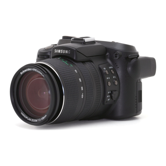
Ⅰ. SPECIFICATION 5. IDENTIFICATION OF FEATURES Front AF passive sensor Self-timer lamp & Auto Focus lamp Shutter button Front Jog dial (JOG 1) Microphone Remote control sensor Lens Microphone Side (Left/ Right) AF lock(AF-L) button Pop-up flash (OPEN) button/ Flash compensation button Remote control sensor High Speed shutter (HS) button Flash... - Page 15 Ⅰ. SPECIFICATION Zoom ring Zoom scale indicator Focus ring Flash EVC (Exposure Value Compensation) ring Hot shoe Shutter button Flash status lamp Drive button ISO button Mode dial Metering button Speaker Power button/ Power lamp Self-timer button Hot shoe cap...
- Page 16 Ⅰ. SPECIFICATION Back Back LCD Rear Jog dial (JOG 2) Strap eyelet AE Lock (AE-L) button/ Strap eyelet Thumbnail button Finder LCD Card in use lamp Diopter adjustment ring Digital zoom/ Enlargement button LCD button Memory card slot cover Display/ Information button Connector cover 5-function button SCENE/...
- Page 17 Ⅰ. SPECIFICATION Bottom Battery chamber cover & lock Tripod socket Diopter adjustmentring Battery chamber Battery chamber Battery holder...
- Page 18 Ⅱ. INSTALLATION 1. Click the [Install] menu in the Auto run frame. The camera driver is installed automatically. 2. Installation is complete. Click the [Finish] button. 3. The Software License Agreement window for DirectX will be displayed. If you agree to this, select [I accept the agreement] and click [Next >] button.
- Page 19 Ⅱ. INSTALLATION 4. A window will open. Click the [Next(N) >] button. 5. DirectX Installation is completed. Click the [Finish] button and then the Digimax Master installation will be started. * The system will not reboot even if you click the [Finish] button.
- Page 20 Ⅱ. INSTALLATION 7. The Digimax Master installation window will be displayed as shown alongside. Click the [Next >] button. ● If you select [Cancel] at step 7, a window for installing Digimax Reader will be displayed. 8. A window will open. Click the [Next >] button. 9.
- Page 21 Ⅱ. INSTALLATION 10. A window will open, asking you to choose a folder to which program icons will be added. Click [Next >] button. If you want to choose another folder, click [Browse..] and choose a folder you want. 11. Click [Install(I)] button and Digimax Master starts installing.
- Page 22 Ⅱ. INSTALLATION 13. A window will be displayed as shown alongside. Click the [INSTALL] button. - If you click the [Manual] button instructions, instructions for using Digimax reader will be displayed. - Click the [EXIT] button and the Digimax reader installation will be cancelled and a window for restarting the computer will appear.
- Page 23 Ⅱ. INSTALLATION 16. A destination selection window will open. Click the [Next >] button. To copy the files to another folder, click [Browse...] and choose a folder you want. 17. Digimax Reader Installation is completed. The system will not reboot even if the [Yes, I want to restart the computer now] option is selected.
- Page 24 Ⅱ. INSTALLATION 20. Turn the camera power on. The [Found New Hardware Wizard] will open and the computer will recognise the camera. * If your OS is Windows XP, an image viewer program will open. If the download window of Digmax Master opens after starting Digimax Master, the camera driver was setup successfully.
- Page 25 2. Refer to FAQ to check for a possible solution to the problem. 3. If your PC’s central processing unit is VIA chip (This is shown in the USB Host Controller), download the patch file from the Samsung Camera web page. (http://www.samsungcamera.com)
-
Page 26: Ⅲ. Exploded View And Parts List
Ⅲ. EXPLODED VIEW AND PART LIST 1. MAIN_1 ASSEMBLY... -
Page 27: Main_2 Assembly
Ⅲ. EXPLODED VIEW AND PART LIST 2. MAIN_2 ASSEMBLY... -
Page 28: Main_3 Assembly
Ⅲ. EXPLODED VIEW AND PART LIST 3. MAIN_3 ASSEMBLY... -
Page 29: Body Assembly
Ⅲ. EXPLODED VIEW AND PART LIST 4. BODY ASSEMBLY... -
Page 30: Front Cover_1 Assembly
Ⅲ. EXPLODED VIEW AND PART LIST 5. FRONT COVER_1 ASSEMBLY... -
Page 31: Front Cover_2 Assembly
Ⅲ. EXPLODED VIEW AND PART LIST 6. FRONT COVER_2 ASSEMBLY Double tape location... -
Page 32: Back Cover Assembly
Ⅲ. EXPLODED VIEW AND PART LIST 7. BACK COVER ASSEMBLY... -
Page 33: Top Cover Assembly
Ⅲ. EXPLODED VIEW AND PART LIST 8. TOP COVER ASSEMBLY... -
Page 34: Shoebase_1 Assembly
Ⅲ. EXPLODED VIEW AND PART LIST 9. SHOEBASE_1 ASSEMBLY... -
Page 35: Shoebase_2 Assembly
Ⅲ. EXPLODED VIEW AND PART LIST 10. SHOEBASE_2 ASSEMBLY... -
Page 36: Others Assembly
Ⅲ. EXPLODED VIEW AND PART LIST 11. OTHERS ASSEMBLY... -
Page 37: Packing Item_1
Ⅲ. EXPLODED VIEW AND PART LIST 12. PACKING ITEM_1 12-13 12-3 12-14 12-8 12-6 12-4 12-5 12-12 12-10 12-11 12-9 12-2 12-1... -
Page 38: Packing Item_2
Ⅲ. EXPLODED VIEW AND PART LIST Ⅲ. EXPLODED VIEW AND PART LIST 13. PACKING ITEM_2 13-1 13-12 13-4 13-3 13-6 13-7 13-5 13-8 13-2 13-9 13-10 13-11... - Page 39 Fig.No Old Code New Code Parts Name Q'ty Supply Remark 1. MAIN_1 ASSEMBLY Q9007236901A AD97-14131A REAR COVER ASSY Q9007237001A AD97-14132A TOP COVER ASSY Q7117010401A AD81-03105A LOGO PLATE Q7014006503A AD81-07619A SHOE SPRING Q9007237201A AD97-14134A BATTERY COVER ASSY Q6003047201A 6003-001704 SCREW Q9761173507 6003-001690 SCREW Q6003047401A AD81-07553A SCREW...
- Page 40 Q9761206007 SCREW 4. BODY ASSEMBLY Q7211079406A AD81-03411A BODY Q7409187001A AD81-05017A BARREL GUIDE SHIELD Q7011051703A AD81-02781A BATTERY CONTACT Q6003047502B 6003-001706 SCREW Q7011051902A AD81-07609A BATTERY LOCK CAM SPRING Q9761173007 6003-001687 SCREW Q7011051401A AD81-08028A AF ADJUST HOLDER Q9761173507 6003-001690 SCREW Q6107061501A DNA AF ADJUST SPRING 4-10 Q9001106001A AD97-13763A JOG1 BASE ASS'Y 4-11...
- Page 41 5-10 Q9008060101A AD97-14898A MODE CONTACT ASSY 5-11 Q9761173007 6003-001687 SCREW 5-12 Q7217351101A DNA H BUTTON 5-13 Q7217342601A DNA AF LOCK BUTTON 5-14 Q7217342701A DNA AF WINDOW BUTTON 5-15 Q7307006102A AD81-04660A SIDE COVER RUBBER 5-16 Q6003047502B 6003-001706 SCREW 5-17 Q3009000101A AD81-00552A MIC 5-18 Q7309045101A DNA MIC RUBBER...
- Page 42 Q7217343801A AD81-04358A LCD BUTTON Q7217343901A AD81-04359A DISPLAY BUTTON Q7217344002A AD81-04360A DELETE BUTTON Q7307006003A AD81-04659A LCD BUTTON RUBBER Q7217344102A AD81-04361A OK BUTTON Q7217344202A AD81-04362A FUNCTION BUTTON Q7217342302A AD81-04349A PLAY BACK BUTTON Q7307005803A AD81-04657A FUNCTION BUTTON RUBBER 7-10 Q7217344403A DNA AE LOCK BUTTON 7-11 Q7217344303A DNA D_ZOOM BUTTON...
- Page 43 8-11 Q7017045003A AD81-08094A TOP FPCB PLATE 8-12 Q7409195601A AD81-05042A EYEPIECE WINDOW TAPE 8-13 Q7409186302A AD81-08397A METAL DOME 8-14 Q7217343502A AD81-04354A TOP LCD WINDOW 8-15 Q7217343004A AD81-04353A POWER BUTTON 8-16 Q7217343103A DNA ISO BUTTON 8-17 Q7217343203A DNA METERING BUTTON 8-18 Q7217343303A DNA DRIVE BUTTON 8-19 Q7217343403A DNA...
- Page 44 10-8 Q9008089201A AD92-00228A STROBO PCB ASSY 10-9 Q9761174507 6003-001693 SCREW 10-10 Q9761173507 6003-001690 SCREW 10-11 Q7214087605C AD81-03755A STROBO UPPER COVER 10-12 Q9761172507 6003-001686 SCREW 10-13 Q7214087705B AD81-03756A STROBO UNDER COVER 10-14 Q7409203601A AD81-08429A LOCK PLATE TAPE 10-15 Q7014006802A AD81-02918A STROBO LOCK PLATE A 10-16 Q7214088003B AD81-03757A FRESNEL LENS 10-17 Q7014006303A AD81-02916A STROBO REFLECTOR 10-18 Q7214088301A DNA...
- Page 45 11-20 Q7013016102A AD81-08084A FINDER MASK 11-21 Q7213036003A DNA EYEPIECE HOLDER 11-22 Q6721009701A DNA OB LENS 11-23 Q6721009801A DNA EYEPIECE LENS 11-24 Q7213035701A DNA FINDER COVER 11-25 Q9761173507 6003-001690 SCREW 11-26 Q7213035901A DNA FINDER EYEPIECE CAM 11-27 Q7213035803A AD81-08228A EYEPIECE KNOB 11-28 Q7309045301A AD81-08369A EYEPIECE O_RING 11-29 Q7013016002B AD81-08083A EYEPIECE KNOB WASHER 11-30 Q7211080404A AD81-03417A JOG1 BASE...
- Page 46 12-11 Q7212188901A AD81-03652A FILTER ADAPTER 12-12 Q7212189001A AD81-03653A LENS HOOD 12-13 Q4719004801A AD81-01073A CHARGER_SBC-L4 12-14 Q4404000101A AD81-00920A AC ADAPTOR_SAC-81 13. PACKING ITEM_2 13-1 Q6909017201A AD81-02634A PE BAG_H1(FOR CAMERA) 13-2 Q6909011601A AD81-02631A PE BAG (FOR ACCESSORY) 13-3 Q6901215501A AD81-02400A PULP_MOLD_H1(TOP/BOTTOM) 13-4 Q6901215601A AD81-02401A PE FORM _H1(TOP/BOTTOM) 13-5 Q4609012301B AD81-01010A DIGIMAX MASTER+DIGIMAX READER...
- Page 47 Q6806279701A DNA U/MANUAL_DIGIMAX H1_FIN Q6806279801A DNA U/MANUAL_DIGIMAX H1_RUS Q6806279901A AD81-01969A U/MANUAL_DIGIMAX H1_CHI(S) Q6806280001A DNA U/MANUAL_DIGIMAX H1_TUR Q6806280101A DNA U/MANUAL_DIGIMAX H1_IND Q6806280201A DNA U/MANUAL_DIGIMAX H1_ARA Q6807002601F DNA WARRANTY CARD_KOREA Q6807003003U 6801-001646 WARRANTY CARD_EXP Q6807012301A 6801-001658 WARRANTY CARD_2 YEARS 13-8 Q6807010903C 6801-001650 WARRANTY CARD_RUS Q6807011301B AD81-02236A WARRANTY CARD_TSOE(CHINA) Q6807009502E 6801-001647...
-
Page 48: Ⅳ. Adjustment
Ⅳ. ADJUSTMENT 1. Digital camera service To take a digital camera service (Repair, Tuning and Checking), the following equipments have to be arranged. The sequences for the camera service are as shown. Receiving the camera 1. Receiving the camera When receiving a camera, check whether the accessories are Checking the camera included or not and ask the customer exact problems. - Page 49 Ⅳ. ADJUSTMENT 1) Equipments for checking and inspection To check and inspect the camera malfunction, the following equipments have to be arranged. ⑥ ④ ③ ② ⑤ ① ⑦ ⑪ ⑧ ⑨ ⑩ Device Description PC for inspection - Installing a digital camera driver or Checking the removable device - Checking the file transference(upload and download) - Playing back the still image or movie clip HARD RACK,...
- Page 50 Ⅳ. ADJUSTMENT 2) Equipments for camera repair To repair the camera, the following equipments have to be arranged. ⑧ ⑩ ⑬ ④ ⑫ ⑨ ③ ⑥ ⑦ ② ① ⑪ ⑤ Device Description A set of tools Pincette/ Screwdriver/ Discharger etc. Cleaning paper For cleaning camera lens and camera parts Detergent container...
- Page 51 Ⅳ. ADJUSTMENT 3) Equipments for camera tuning To tune the camera, the following equipments have to be arranged. ⑤ ② ④ ① ⑥ ③ Device Description AE TESTER For tuning AE and STROBE AWB LIGHT For checking and tuning AWB SOURCE BOX COLOR chart For checking AWB and color of images...
- Page 52 - When the cable is inserted, check whether the images play back on the external monitor. Turn on the camera. - Check whether the green LED is blinking, SAMSUNG LOGO is on and the start-up sound sounds. - Check the “L” and “FINE” icon on the LCD monitor.
- Page 53 Ⅳ. ADJUSTMENT Checking item Check point MANUAL focus. - Check whether the icon and counter are displayed on the LCD monitor. Take a movie clip with TELE zoom - Check whether the recording time is displayed and there are a during 10 seconds.
-
Page 54: Adjustment Items By Changed Parts
Ⅳ. ADJUSTMENT 2. Adjustment items by changed parts After changing the electronic parts of Pro 815, the parts have to be adjusted in accordance withe the adjusted items. The items listed on the table are have to be adjusted after changing. PROCESS MAIN STROBO... - Page 55 Ⅳ. ADJUSTMENT 3. Holding the Delete button, press the Right button and press the Shutter button for about 2 seconds. ④ ④ ① ① ② ② 4. Menus for developer will display. To check the firmware version, select "1. Confirm version" and press the OK button. D D e e v v e e l l o o p p e e r r m m o o d d e e 0 0 1 1 .
- Page 56 Ⅳ. ADJUSTMENT 3) How to update the FIRMWARE ※ When the firmware is updated, all of data stored in the memory will be deleted. You must backup the data before updating. The firmware file name must be "H1_MAIN.elf" and use the AC ADAPTOR or fully charged battery. 1.
- Page 57 Ⅳ. ADJUSTMENT D D e e v v e e l l o o p p e e r r m m o o d d e e 1 1 . . C C o o n n f f i i r r m m v v e e r r s s i i o o n n 2 2 .
-
Page 58: Ⅴ. Pattern Diagram
Ⅴ. PATTERN DIAGRAM 1. PARTS ARRANGEMENT FOR EACH PCB ASS’Y 1) MAIN_TOP... -
Page 59: Main_Bottom
Ⅴ. PATTERN DIAGRAM 2) MAIN_BOTTOM... -
Page 60: Power_Top
Ⅴ. PATTERN DIAGRAM 3) POWER_TOP... -
Page 61: Power_Bottom
Ⅴ. PATTERN DIAGRAM 4) POWER_BOTTOM... -
Page 62: Strobo_Top
Ⅴ. PATTERN DIAGRAM 5) STROBO_TOP... -
Page 63: Strobo_Bottom
Ⅴ. PATTERN DIAGRAM 6) STROBO_BOTTOM... -
Page 64: Afe_Top
Ⅴ. PATTERN DIAGRAM 7) AFE_TOP... -
Page 65: Afe_Bottom
Ⅴ. PATTERN DIAGRAM 8) AFE_BOTTOM... -
Page 66: Top
Ⅴ. PATTERN DIAGRAM 9) TOP... - Page 67 Ⅴ. PATTERN DIAGRAM 10) TOP...
-
Page 68: Ⅵ. Troubleshooting
Ⅵ. TROUBLESHOOTING 1. POWER ON DEFECT Check the power (Battery, Adaptor, etc.) 1. Check the connections between the each PCB. (TOP FPCB-TOP PCB-MAIN, POWER-MAIN) If the consumption of 2. Check the connection of battery L/W. current is 0mA 3. Check the condition of F1 (FUSE). If the both terminals are between 0~0.03Ω, it has no problem. - Page 69 Ⅵ. TROUBLESHOOTING...
- Page 70 Ⅵ. TROUBLESHOOTING If the F1 (FUSE) is damaged, there is no the consumption of current(0mA) after turning on the camera. Check the connection of JOG FPCB and MAIN PCB BATTERY L/W If the Q5 is damaged, the camera can't be turned on. Door Switch If the Door switch is transformed or badness, the current comes...
- Page 71 Ⅵ. TROUBLESHOOTING LENS F PCB CCD F PCB If the assembling condition of CCD FPCB and LENS FPCB is bad, the current comes down from 200mA to 0mA and the camera can't operate. If an incorrect CF CARD is inserted, Q1 may be damaged.
-
Page 72: Defect Related To The Lcd
Ⅵ. TROUBLESHOOTING 2. Defect related to the LCD No image and OSD are CCD error displayed on the LCD monitor Check whether an image is displayed on the external If no image is displayed on the external monitor, it is CCD monitor after connecting related error (Refer to the Defect related to the CCD) the AV jack. - Page 73 Ⅵ. TROUBLESHOOTING Check the assembling condition of the 3.5" TFT LCD FPCB The TOP LCD is whitened → → The LCD FPCB is torn Check the assembling condition of TOP LCD FPCB Check the assembling condition of EVF FPCB...
- Page 74 Ⅵ. TROUBLESHOOTING Status Cause & Solution Horizontal noise Assembling error of Shutter F PCB Pattern is cut off caused by assmebling error of Shutter F PCB on the AFE PCB When the L1 and D1 on the TOP PCB has error or LCD Driver IC pattern (No.
- Page 75 Ⅵ. TROUBLESHOOTING The LCD is whitened 1. Check whether an image is displayed on the external monitor by connecting the AV cable. 2. If an image is displayed, check the parts of LCD and LCD FPCB. 3. If an image is not displayed, the MAIN PCB has error.
-
Page 76: Defect Related To The Ccd
Ⅵ. TROUBLESHOOTING 3. Defect related to the CCD Check whether an image is displayed on the external monitor If an image is displayed, refer to the Defect related to the LCD. by connecting the AV jack Check the connection of AFE Check the assembling condition of CCD FPCB and LENS PCB and MAIN PCB FPCB... -
Page 77: Defect Related To The Charging
Ⅵ. TROUBLESHOOTING 4. Defect related to the charging Main Condenser Check the Charging voltage Q11 or U11 error (Approx. 300V) Check the parts of Main 1. Check the connection of Main Condenser L/W Condenser 2. Check the condition of parts of Main Condeser Check the parts on the 1. - Page 78 Ⅵ. TROUBLESHOOTING Main Condenser L/W Check the connection of Strobe PCB and Strobe FPCB Q15:IGBT T2:Transformer...
-
Page 79: Defect Related To The Flash
Ⅵ. TROUBLESHOOTING 5. Defect related to the Flash Main Conde Check the charging voltage Refer to the Defect related to the Charging (Appox. 300V) Check the XE TUBE condition (Breakage, incorrect assembly) Check the condition of Trig Coil < How to check the Q15 IGBT > ・1, 2, 3+4 = about 4.7KΩ... -
Page 80: Defect Related To The Pop-Up
Ⅵ. TROUBLESHOOTING 6. Defect related to the POP-UP Check the assembling condition of Strobe PCB and Strobe FPCB 1. Check the soldering condition of Solenoid Check the condition of 2. Check the assembling condition of Strobe Lock Lever and Solenoid Solenoid When the camera is turned on, the flash POP-UP unit is... - Page 81 Ⅵ. TROUBLESHOOTING Check the connection of Strobe PCB and Strobe F PCB Check the assembling condition of Strobe Lock Lever and Solenoid Check the soldering condition of Solenoid Check the Strobe Detect SW Check the assembling condition of Pop up Spring There is short-circuit between the Solenoid (-) and Shoe Plate...
-
Page 82: Defect Related To The Card
Ⅵ. TROUBLESHOOTING 7. Defect related to the CARD Insert the card in If the same error is happened, it is card error the other camera Format the card and insert again Check the connection of Check the assembling condition of Card FPCB and Main PCB card F PCB When the camera is turned Check the condition of Q1 on the Main PCB... - Page 83 Ⅵ. TROUBLESHOOTING Check the assembling condition of Card FPCB and Main PCB Check the Card Pin, soldering condition and tear of FPCB DO NOT WASH...
-
Page 84: Defect Related To The Mode Dial
Ⅵ. TROUBLESHOOTING 8. Defect related to the Mode dial Check the connection of Check the assembling condition of Top F PCB and Top PCB TOP F PCB Check the condition of Check the tear of PCB, condition of Swiches, dirt of Mode dial Top FPCB contactor Check the Mode dial... -
Page 85: Defect Related To The Audio
Ⅵ. TROUBLESHOOTING 9. Defect related to AUDIO - First of all, check that the AUDIO is ON in the MENU. - When the MIC & SPEAKER are soldered, be careful of breakage by a high temperature. Check the soldering condition of speaker and L/W of microphone Check the condition of parts... -
Page 86: Defect Related To The Usb, Av And Dc Jack
Ⅵ. TROUBLESHOOTING 10. Defect related to the USB, AV and DC jack Check the assembling condition of Power PCB and Main PCB Check the condition of jacks USB JACK, DC JACK, AV JACK on the Power PCB Check the assembling condition of Power PCB and Main PCB AV JACK, USB JACK, DC JACK... -
Page 87: Ⅶ. Service Information
Ⅶ. SERVICE INFORMATION 1. The order of disassembly and assembly ■ Caution 1. Do the disassembling and assembling camera where the blocking static electricity mat is on the table. 2. When handling the major PCBs of camera, please wearing the band which cuts off the electric current on the wrist. - Page 88 Ⅶ. SERVICE INFORMATION ■ ■ The order of disassembly 4. Disassemble the LENS CAP 1. Disassemble the BACK COVER MORTOR ASS’ Y 2. Disassemble the STRAP eyelet 5. Disassemble the CARD F PCB COVER 6. Disassemble the MIDDLE 3. Disassemble the FRONT COVER COVER ASS’...
- Page 89 Ⅶ. SERVICE INFORMATION 1. Remove the screws. a X 1 b X 1 2. Remove the screws. c X 1 d X 1 ※ b screw is located under the GRIP. 3. Remove the screws located under the camera body. e X 4...
- Page 90 Ⅶ. SERVICE INFORMATION 4. Disassemble the camera as shown. The battery cover must be opened. 5. When disassembling the Back cover, remove the LCD F PCB and R BACK F PCB from connector carefully. 6. Disassemble the Top cover. When disassembling, remove the TOP F PCB carefully.
- Page 91 Ⅶ. SERVICE INFORMATION 6. Back cover is disassembled. 7. To disassemble the Power PCB, remove the screws and L/W. f X 2 STROBO(-)(+) BAT.(+) BAT.(-) BAT.(-) 8. Disassemble the Power PCB. (When disassembling, take care of MAIN PCB and CONNECTOR)
- Page 92 Ⅶ. SERVICE INFORMATION 9. To disassemble the Card F PCB, remove the screws. g X 2 10. Disassemble the Card F PCB. In this case, take care of a point fixed with a double-stick tape. 11. Remove the Card F PCB from the Main PCB.
- Page 93 Ⅶ. SERVICE INFORMATION 12. To disassemble the Main F PCB, remove the screws and Side F PCB. i X 4 MIC_L(-) MIC_R(+) MIC_R(-) MIC_L(+) SIDE F PCB SPK_R(-) SPK_R(+) Remove the speaker and microphone L/W. SPK_L(+) SPK_L(-) 14. To disassemble the finder, remove screws. j X 4 15.
- Page 94 Ⅶ. SERVICE INFORMATION 16. After disassembling the LCD PRESSURE, remove the screws on the LCD BOLDER. k X 2 17. After removing the LCD PRESSURE from the LCD HOLDER. 18. Disassemble the TOP PCB from the MAIN PCB. When disassembling, take care of the MAIN PCB and TOP PCB.
- Page 95 Ⅶ. SERVICE INFORMATION 19. Disassemble the finder with TOP PCB. 20. Disassemble the CCD F PCB Condenser connected with the Main PCB and Lens F PCB condeser. LENS F PCB CCD F PCB 21. The Main PCB is disassembled. To disassemble the Barrel, remove the screws. l X 4...
- Page 96 Ⅶ. SERVICE INFORMATION 22. Remove the screws on the Tripod. m X 2 n X 2 23. Disassemble the Bottom cover and Tripod. 24. Disassemble the Barrel.
- Page 97 Ⅶ. SERVICE INFORMATION 25. To disassemble the Side cover, remove the screws. o X 2 26. Disassemble the Side cover. 27. To disassemble the Front cover, remove the screws. p X 4...
- Page 98 Ⅶ. SERVICE INFORMATION 28. Disassemble the Barrel holder plate. 29. To disassemble the Body and Front cover, remove the screws. q X 4 30. Disassemble the Body and Front cover.
- Page 99 Ⅶ. SERVICE INFORMATION 31. Disassemble the Shoe spring from the Shoe. ※ How to disassemble Lift up the front of the Shoe spring and push it back Shoe Shoe spring 32. Push aside the Shoe spring and disassemble.
- Page 100 Ⅶ. SERVICE INFORMATION 33. To disassemble the Shoe ass'y, remove the screws. r X 2 34. Remove the screws on the front of the Shoe ass'y. s X 2 35. Disassemble the Shoe ass'y.
- Page 101 Ⅶ. SERVICE INFORMATION 36. Remove the Main Condenser L/W. White Purple 37. Disassemble the Shoe ass'y. 38. After disassembing the Shoe ass'y...
- Page 102 Ⅶ. SERVICE INFORMATION Attached position of EMI Sheet 1. TOTAL BARREL ASS'Y AF MOTOR EMI SHEET AF MOTOR EMI SHEET (Q7409208801A) (Q7409208801A) AFE SUB PCB TAPE (Q7409209801A) BARREL HOLDER PLATE TAPE (Q7409194601A) SHUTTER EMI SHEET (Q7409209701A) AFE SUB COPPER TAPE (Q7490210001A) SENSOR EMI SHEET (Q7409209601A)
- Page 103 Ⅶ. SERVICE INFORMATION 3. POWER PCB ASS'Y BATTERY SUB CONTACT TAPE X 2 (Q7409167501A) 4. FINDER ASS'Y EVF EMI SHEET (Q7409209101A)
- Page 104 Ⅶ. SERVICE INFORMATION 5. BARREL HOLDER PLATE BARREL HOLDER PLATE TAPE (Q7409194601A) 6. BODY BODY TAPE A (Q7409195801A) AF MOTOR EMI SHEET X 2 (Q7409208801A)
- Page 105 Ⅶ. SERVICE INFORMATION STROBO WITE TAPE (Q7409193001A) AF MOTOR EMI SHEET X 2 (Q7409208801A) SENSOR EMI TAPE (Q7409209601A) JOG FPCB EMI TAPE A (Q7409209201A) JOG FPCB EMI TAPE B (Q7409209301A) BODY COPPER TAPE (Q7409209901A)