Table of Contents
Advertisement
Quick Links
Advertisement
Table of Contents

Related Manuals for Makita XUC01


Summary of Contents for Makita XUC01
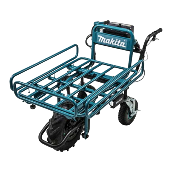
- Page 1 BATTERY POWERED WHEELBARROW XUC01 REPAIR MANUAL March 2018 Ver.1...
-
Page 2: Table Of Contents
CONTENTS CONTENTS ....................................2 CAUTION ....................................3 NECESSARY REPAIRING TOOLS ............................3 FASTENING TORQUE ................................4 LUBRICANT AND ADHESIVE APPLICATION ........................4 REPAIR ......................................5 Battery ....................................5 6-1-1 Disassembling ................................5 Frame ....................................5 6-2-1 Disassembling ................................5 Battery box ................................... 6 6-3-1 Disassembling (Repair can be done with Upper frame) .................... -
Page 3: Caution
CAUTION Repair the machine in accordance with “Instruction manual” or “Safety instructions”. Follow the instructions described below in advance before repairing: ・ Wear gloves. ・ In order to avoid wrong reassembly, draw or write down where and how the parts are assembled, and what the parts are. It is also recommended to have boxes ready to keep disassembled parts by group. -
Page 4: Fastening Torque
M16x1.5 Hex nut LUBRICANT AND ADHESIVE APPLICATION Apply the following lubricants and adhesives. Lubricant Amount a little Makita grease FA. No.2 Bead cream (commercial product) a little Fig. 1 Outer periphery of Sleeve 17 Outer periphery of Snap in Valve... -
Page 5: Repair
REPAIR Battery 6-1-1 Disassembling Remove Battery from the machine before repair. Frame 6-2-1 Disassembling Fig. 1 Release Rock lever [1]. Loosen M8x25 Thumb screw [3] (4pcs) and remove Spring washer 8 [4], Flat washer 8 [5], M8x50 Hex bolt [6], M8x75 Hex bolt [7] (2pcs) and then remove Frame [2]. -
Page 6: Battery Box
Battery box 6-3-1 Disassembling (Repair can be done with Upper frame) Fig. 3 Remove four M5x14 H.S.H.Bolt WR [1] with 1R015-A and Impact driver and take out Battery box assembly [2]. Tips Prepare a workbench [3] to put Battery box assembly [2]. 1R015-A Fig. -
Page 7: Assembling
6-3-2 Assembling Fig. 7 Insert claw portion of Terminal [2] into the groove of Ceter case [1]. Put Terminal holder[4] onto Center case [1] so as not to pinch Lead wires and then fasten them with PT 3x16Tapping screws [3] (2 pcs). Fig. -
Page 8: Switch Box
Switch box 6-4-1 Disassembling Fig. 9 Remove M8x20 Hex bolt [1] and M8x40 Collar bolt [2]. Then pull off Handle R [4] from Sub frame [3]. Tips Prepare a workbench or a box to put Handle R [4]. Fig. 10 Remove Binding PT 3x16 Tapping screw [1] (5 pcs) and open Switch box L [2]. -
Page 9: Assembling
6-4-2 Assembling Fig. 12 Assemble Switch lever [1] and Torsion spring 11 [2] as shown in the left Fig. Fig. 13 Assemble Switch plate [1] by connecting Connector to Switch box through the bottom of pipe of Handle R. Fig. 14 Assemble Pipe clamp 28 [1] if they are disassembled. -
Page 10: Led Light
LED light 6-5-1 Disassembling Fig. 16 (In case of replacing only LED lights) Remove only inside Bind PT 3x16 Tapping screws [2] (2 pcs). Then LED light assembly [1] can be disassembled. Fig. 17 Remove CT 4x16 Tapping screws [1] (4pcs) and remove Light case cover [2] (Left/ right both Lights) [4] [5] Tips... -
Page 11: Assembling
Fig. 20 Loosening engagement of Clamp A [1] and Clamp B [2] remove LED light assembly [4]section from Lower frame [3]. 6-5-2 Assembling Fig. 21 Assemble Reflector [1] by engaging four protrusions with four holes on LED circuit [1]. Though bottom shape of Reflector is rectangular, it is non-directional. -
Page 12: Brake
Brake 6-6-1 Disassembling Fig. 23 Loosening M6x18 H.S.H bolt W/WR [1] (2 pcs) of Brake caliper assembly, pull off Brake cable through Adjust screw section [2]. Fig. 24 Removing M6x18 H.S.H bolt W/WR [1] (2 pcs) remove Brake caliper assembly [3] from Lower frame [2]. Fig. -
Page 13: Assembling
Fig. 26 Pull off Brake cable [3] by adjusting slit of Adjust screw of Brake assembly [1]. Pulling up Brake lever [4], remove nipple of Brake cable [3] from Brake lever [4]. Fig. 27 Remove Hex socket bolts (2 pcs) [1] and Brake assembly [3] from Handle complete. -
Page 14: Front Tire, Wheel (Motor)
Fig. 30 Temporary fasten Brake caliper with M6x18 H.S.H bolts W/ WR [1]. 1R36 Inserting 1R366 (0.1mm) between Brake disc [2] and Brake pad [3] support Lever [3] to apply Brake effectively. Eliminating the sagging of Brake cable, fasten Hex socket bolts [1] (2 pcs) and then a Hex socket bolt [5] to fix Brake cable. - Page 15 Fig. 33 Remove Front tire 430 [1] by lifting it up from Lower frame [2]. Note Two Washer [3] are attached at both left and right side of axle. Two Coned disc spring 16 [4] are attached at opposite side of Brake.
- Page 16 Fig. 37 Remove Wheel [3] with a Lever for replacing tire [1] from Front tire 430 [2]. Fig. 38 Pull off Snap in valve [1] from Wheel [2] by pushing it with Arbor press and 1R283 etc. 1R283 16 / 41...
-
Page 17: Assembling
Fig. 39 Grasp Snap in valve [1] with a plier and pull off from Wheel [2]. 6-7-2 Assembling Fig. 33 Apply Bead cream [3] to insert surface of Snap in valve [1] and a mounting hole [2] of Wheel all around. Insert Snap in valve [1] into the hole [2] of Wheel by picking up screw side of Valve [1] to pass through the hole. - Page 18 Fig. 42 Insert the Yellow line side of Front tire 430 [1] into Brake disc side of Wheel and engage lower side of Beads with a Lever [2] for replacing tire. Tips Be careful not to make a damage to Wiring of Motor [3] Yellow line and Snap in valve [4] and assemble Front tire 430 [1].
- Page 19 Fig. 46 Prepare some wood stand to put Wheel.( only Wheel to turn Front tire) Put the wiring side of Wheel upward. Engage bead of Front tire 430 and Wheel by pushing down the tire. And then pump up to be engaged completely. Wood stand Fig.
-
Page 20: Puncture Repair Of Front Tire 430
Fig. 35 When Band to connect each wiring is cut with a nipper all Bands must be replaced with a new one. After fastened with a new one extra Band must be cut down. Puncture repair of Front tire 430 Puncture repair of Front tire is to be consigned to outside Repair agency such as Auto-repair shops. -
Page 21: Circuit Diagram
CIRCUIT DIAGRAM Motor section Battery Insertion section Motor Power supply cord Grommet Closed end splice 1.5mm Green AWG 14 Green AWG 14 Blue 1.5mm Blue AWG 14Yellow 1.5mm Yellow Wire diameter is 0.2mm AWG 28 Connector Line filter Grommet Brake operation section Line filter Connector AWG 26... - Page 22 Connector Line filter AWG 26 AWG 26 Battery Buzzer circuit Insertion section AWG 26 AWG 26 Switch for Connector illumination Switch for AWG 28 (7 pcs) Fuel gauge LED circuit AWG 28 board LED circuit board AWG 28 (4 pcs) Connector Main switch Lead unit...
-
Page 23: Wiring Diagram
WIRING DIAGRAM Center case section 8-1-1 Assembling of Controller Fix Controller with these Hooks. Line filter if it is used) Put Line filter Controller lead wire (orange, white, blue) connected to Terminal (Key side) in this space. (If it is used) Pass Controller lead wire connected to Terminal through the Opening. -
Page 24: Assembling Of Other Than Power Supply Cord
8-1-3 Assembling of other than Power supply cord Fig.:Drawing after repair <Area B> <Area A> <Assembling of Area A> Put Lead wires in the below area to avoid pinching. Lead unit (for connecting to Key) ・between Cover and Lead unit (for connecting Key) ・between Cover and Center case Cover Put Electrolytic capacitor... - Page 25 <Assembling of Area B> Assemble Buzzer circuit as shown below. Buzzer circuit Route Controller lead wire connected to Sub controller The cross section between A – A’ complete through this space. Put Lead wires of Buzzer circuit in this Lead holder. Don’t make a slack between Buzzer circuit and Line filter A with Controller, without Tube)
- Page 26 ・ Tape A , Tape B: Sub controller complete (without Switch) for bundling Lead wire Put Tape B in left or right groove as shown below. Lead wires of Sub controller complete (without Switch) Don’t put any Lead wires on this Rib. must be tight.
- Page 27 <Assembling of Area B> Put Line filter A as shown below (left side of Hook) Avoid pinching of Lead wires between Line filter A and Center case, Controller case. Rib of Center case Rib of Center case Line filter A Hook Controller case The cross section between A –...
-
Page 28: Assembling Of Power Supply Cord
8-1-4 Assembling of Power supply cord Fig.:Drawing after repair Cord for Motor Cord for LED light Relay cord for Switch box Cord for Brake Assembling of Relay cord for Switch box and Cord for LED light < > Put Connector of Relay cord for Switch box in this space as shown below. 4 pins 10 pins Put Closed end splice of which... - Page 29 Put Connector of Cord for LED light in the space as shown below. Put Sheath of Cord for LED light in this space. Cord for LED light Line filter of Cord for LED light Relay cord for Switch box Put Line filter of Cord for LED light in this space. Don’t put any Lead wires on Ribs.
- Page 30 Assembling of Cord for Motor and Cord for Brake < > Tip of Sheath of Cord for Motor should not be jumped out from root of Controller lead wire (Signal wire connecting to Motor and Brake) Assemble Front cover while Battery changeover switch is come out of Center case.
-
Page 31: Assembling Of Battery Changeover Switch
Lead wires should not be jumped out from Opening toward Terminal. Opening 8-1-5 Assembling of Battery changeover switch Assemble Battery changeover switch after Front cover is assembled to Center case. Battery changeover switch Assemble Battery changeover switch as shown above. Front cover 31 / 41... -
Page 32: Switch Box Section
Switch box section Switch plate complete Don’t put Connector so that Lead wire of Switch plate complete faces to Switch terminal side. Connector of Switch plate complete Switch terminal Switch Switch plate complete Assemble Flag receptacle as shown Assemble area A above. -
Page 33: Led Light Case Section
LED Light case section Right side < > Assemble the tip of Sheath of Power supply cord (with two Connectors) in this zone. Route Lead wire of LED circuit through this groove. Assemble Power supply cord unit (with two Connectors) at this side. Don’t make a slack in this space. -
Page 34: Fixing Of Band
Fixing of Band Band assortment Band A(687849*1) : Band B(687410*4) : Band A, B Pull the Band until the gap with Cord and Pipe will be eliminated. Cut off unnecessary Band. *The cut end must be Max 3mm. Max 3mm Sec. -
Page 35: Wiring
Wiring 8-5-1 Position 1 Color index of cords' sheath Wheel Battery box Battery box Brake section section Brake Battery box Switch box Battery box Wheel Brake wires Light case Light case (left side) Light case Battery box Wheel section Switch box... -
Page 36: Position 3
8-5-2 Position 2 Color index of cords' sheath Wheel Battery box Battery box Brake section section Brake Battery box Switch box Battery box Wheel Brake wires Light case Light case (left side) Light case Battery box Position 2 Switch box Wheel section... -
Page 37: Position 5
8-5-3 Position 3 Color index of cords' sheath Wheel Battery box Battery box Brake section section Brake Battery box Switch box Battery box Wheel Brake wires Light case Light case (left side) Light case Battery box Position 3 Wheel section Switch box... -
Page 38: Position 7
8-5-4 Position 4 Color index of cords' sheath Wheel Battery box Battery box Brake section section Brake Battery box Switch box Battery box Wheel Brake wires Light case Light case (left side) Light case Battery box Wheel section Switch box Position 4... - Page 39 8-5-5 Position 5 Color index of cords' sheath Wheel Battery box Battery box Brake section section Brake Battery box Switch box Battery box Wheel Brake wires Light case Light case (left side) Light case Battery box Wheel section Switch box Position 5...
- Page 40 8-5-6 Position 6 Battery box Color index of cords' sheath section Wheel Battery box Brake section Position 6 Brake Battery box Switch box Battery box Wheel Brake wires Light case Light case (left side) Light case Battery box Wheel section Switch box...
- Page 41 8-5-7 Position 7 Color index of cords' sheath Wheel Battery box Battery box Brake section section Brake Battery box Position 7 Switch box Battery box Wheel Brake wires Light case Light case (left side) Light case Battery box Wheel section Switch box...