vimec V65 B.I. Use And Maintenance
Hide thumbs
Also See for V65 B.I.:
- Original instructions manual (88 pages) ,
- Manual (19 pages) ,
- Original instructions manual (86 pages)
Table of Contents
Advertisement
USE AND MAINTENANCE
INSTALLATION INSTRUCTIONS
PARTS CATALOGUE
DATE ____________ APPROVED ____________
VIMEC reserves the right to make modifications and changes to its products at any moment in response to developments in
STAIRLIFT
V 65 ELECTRONIC
MODEL
B.I. - INDEPENDENT ARMS
B.C. - LINKED ARMS
B.R. - RETRACTABLE ARMS
MANUAL CODE
7 5 1 2 0 4 0 / c
22 - 01 - 2007
technology.
Via Parri, 7 (I) - 42045 Luzzara (RE)
Tel.0522/970666 r.a.- Fax.0522/970919
Pages 03 - 15
Pages 16 - 39
Pages 40 - 73
Advertisement
Table of Contents

Related Manuals for vimec V65 B.I.


Summary of Contents for vimec V65 B.I.
- Page 1 MANUAL CODE 7 5 1 2 0 4 0 / c DATE ____________ APPROVED ____________ 22 - 01 - 2007 VIMEC reserves the right to make modifications and changes to its products at any moment in response to developments in technology.
- Page 2 VIMEC S.R.L. Declaration of Conformity “CE” DECLARATION OF CONFORMITY The manufacturer: Via Parri n.7, 42045 Luzzara (R.E.) ITALIA Tel. 0522/970666 r.a. Fax 0522/970919 declares under its own responsibility that the wheelchair stairlift model: V65 - B.I. - B.C. - B.R.
-
Page 3: Contents Of The Manual
7502040 USE AND MAINTENANCE CONTENTS OF THE MANUAL 1. Unit and manufacturer identification Page 2. After-Sales Service Page 3. Description of unit Page 4. Technical data Page 5. Intended and improper uses Page 6. Preparing the lift for operation Page 7. - Page 4 7502040 1) UNIT AND MANUFACTURER IDENTIFICATION I - 42045 LUZZARA (RE) Via Parri N° 7 - Tel. 0522 / 970666 TYPE SERIAL NUMBER (Nr) - - - - YEAR OF MANUFACTURE - - - - WORKING LOAD (Kg) - - - POWER SUPPLY (V / A / Hz) 230 / 5 / 50 WORKING LOAD - - - kg...
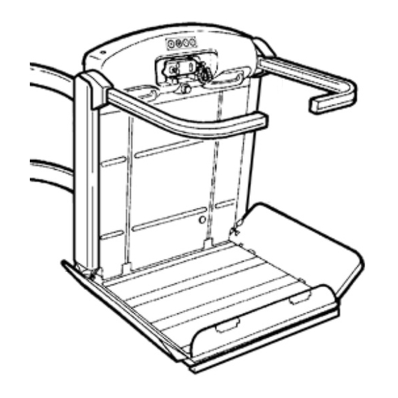
- Page 5 7502040 3) DESCRIPTION OF THE UNIT FIG.2 3.1) Description Car - Fig. 1 Comprises: - carriage. - frame. - protection arms- Fig. 1/a. - platform - Fig. 1/c. - casing - Fig. 1/b. - control panel - Fig. 1/d. Contains: The control panel carries the following: - controls on/off key - Fig.
- Page 6 - Frame with carriages - Fig. 6 and Fig.7/b. - Set of arms- Fig. 7/f. - Platform - Fig. 7/c. - Casing - Fig. 7/d. - Handwheel for manual operation - Fig. 7e. The lift system must be installed by skilled staff authorised by VIMEC. FIG.7...
- Page 7 7502040 3.6) Reference technical standards EN 60204-1 Safety of machinery: Electrical equipment of machines. The lift complies with the following standards: Part 1: General rules. 98/37/EC EN 50081-1 Electromagnetic Compatibility: 98/79/EC Generic emission standard. Residential, commercial and light industry. Machinery Directive and subsequent amendments. EN 50082-1 Electromagnetic Compatibility: EN 292-1 Safety of machinery: Generic immunity standard.
- Page 8 7502040 5) INTENDED AND IMPROPER USES 5.1) Intended Uses The stairlift is a system for transporting passengers SEATED IN A WHEELCHAIR OR ON A SPECIAL SEAT (optional), suitable for installation on staircases having the following characteristics: - Location: Indoors and outdoors - Steps: Parallel - Gradient:...
- Page 9 7502040 7) CORRECT USE OF THE STAIRLIFT IN INDEPEN- button pressed and the arm and flap on the up side DENT ARM AND RETRACTABLE ARM VERSIONS automatically move to the disembarkation position. The flap and arm on the down side are now locked in the WARNING: READ THIS MANUAL CAREFULLY safety position, ensuring safety during disembarkation BEFORE USING THE LIFT.
- Page 10 7502040 6) When the down button (Fig. 9/d) is pressed the flap FIG.11 and arms on the up side automatically locate in the safety position and the lift starts. 7) The lift stops at the destination floor; keep the down button (Fig.
- Page 11 7502040 7.3) Lift operated by attendant FIG.13 If the person using the lift is not self-sufficient, it must be operated by another person (their attendant), who will use the same control panel - Fig. 2. The attendant will follow the lift up or down the stairs on foot.
- Page 12 WARNING: In the event of a system failure or if the safety gear is tripped, call in the VIMEC authorised after-sales service. In the event of a malfunction of any kind, put the lift out of use by turning the key (Fig.
- Page 13 STOP button every month. If the STOP button does not cut out all lift movements, DO NOT USE the lift !! Call in an authorised VIMEC technician at once. 9.1) Precautions for long periods of disuse: WARNING: If the lift is to be out of use for...
- Page 14 - Restore the power supply and press the down button Skill level required: SO: Skilled operative authorised until the hook engages. The stairlift will stop when the by VIMEC. hook depresses the safety microswitch. - Reset the safety gear by moving the stairlift upward by hand (see point 7.6 ).
- Page 15 Power supply failure Check the power supply; see point 7.6, (Manual operation). A safety device has been tripped Call a VIMEC authorised technician The lift descends more quickly Safety gear tripped Call a VIMEC authorised technician than usual then cuts out...
-
Page 16: Table Of Contents
7602040 INSTALLATION INSTRUCTIONS CONTENTS OF THE MANUAL 1. System supply package Page 17 2. Installing the lower rail Page 18 3. Installing the upper rail Page 20 4. Fitting the carriage Page 21 Positioning the charging station (if applicable) Page 23 6. -
Page 17: System Supply Package
7602040 1) SYSTEM SUPPLY PACKAGE WARNING: Remove the arm assemblies (Fig. 1/c) before fitting the carriages onto the rails. The system supply package consists of the following: Casings and on-board control panel (Fig. 1/d). Main structure (Fig. 1/a) Complete with gear motor, drive components with safety WARNING: Remove the upper and lower casings gear and electrical system. -
Page 18: Installing The Lower Rail
7602040 2) INSTALLING THE LOWER RAIL FIG.5 - Use the assembly markings (Fig. 3/b) to identify the first section of rail, with the bend (Fig. 3/a) starting from the top floor. N.B.: If there are no bends, find the first straight section (Fig. - Page 19 7602040 - Set the bend connection fixtures perfectly vertical complete (Fig. 8/f). (Fig. 7) and tighten both the fixing screws once adjust- - Install all the sections of rail except the last one as ment is complete (Fig. 7/a). just described, down to the bottom of the staircase. N.B.: Check that the part of the lower rail (Fig.
-
Page 20: Installing The Upper Rail
(Fig. 10/b) installed on the rail instead of the intermediate mounts (1 or 2 per flight of stairs) is recommended. (Ask the Vimec serv- ice department for these, since they are not part of the supply package). -
Page 21: Fitting The Carriage
7602040 4) FITTING THE CARRIAGE FIG.15 - the main structure, complete with carriages, in the parking area at the bottom floor. - Screw the M10x30 screw (Fig. 15/a) with washer (Fig. 15/b) onto the clutch plate assembly in order to release the upper carriage from the clutch assembly. - Page 22 7602040 - Make the joint in the busbar (Fig. 17/d) as described the rail (Fig. 19/e), firmly tighten the screws (Fig. 19/a earlier. and 19/f). - Fit the upper rail (Fig. 18/a) into the carriage - Version without busbar (Fig. 18/b) and use the upper handwheel (Fig. 18/c) to - Put the brush-holder unit back in its initial position, insert it until a joint is formed with the rail (Fig.
-
Page 23: Positioning The Charging Station (If Applicable)
7602040 When assembly of the rail is complete, for lifts with and the positive pole (red wire) is to the right (Fig. 22), constant gradient of less than 20°, check the gradient when looking at the rail from the rear. The charging of the entire rail (maximum permitted error 1°) before shoes must have the slanting side (Fig.22.a) facing so that the contacts on the carriage can easily slide onto... - Page 24 7602040 - Move the stairlift to a position where it does not get FIG.23 in the way of the assembly procedure, then pass the cables from the power supply unit through the hole shown Fig.23a (female connection) and connect them to their respective contacts (male connection) respect- ing the polarity.
-
Page 25: Connecting The Power Supply Unit
7602040 6) CONNECTING THE POWER SUPPLY UNIT - Connect the wires (positive and negative) to the busbar terminal provided, fixed to the rail (Fig. 27/a- Fig. 27/b). FIG.27 - Connect the 230 V 50 Hz power supply to the power socket (Fig. - Page 26 7602040 N.B.: Move the lift up to the 1st rigid connection and if it WARNING: all safety devices are deac- is not horizontal, screw down the M10x30 screw (Fig. tivated (the operator is responsible for ensuring 15/a) with washer (Fig. 15/b) onto the clutch assembly safety).
-
Page 27: Fixing The Connecting Feet
7602040 8) DEFINITIVE INSTALLATION OF THE MOUNTING FIG.33 FEET After performing a lift trial run to make sure that every- thing has been assembled correctly, the next step is to fix the mounting feet to the floor and the connections to the wall (where possible, in the latter case). -
Page 28: Fitting The Arms
7602040 9) FITTING THE ARMS 9.1) Independent Arms – Connected Arms In the bottom of the bar, connect the wire (Fig. 36/e) Fit the arm supports (Fig. 36/b) on the lift frame to the platform interlock system (Fig. 36/f). (Fig. 36/a), aligning the locator pins provided (Fig. -
Page 29: Fitting The Platform With Motor-Operated Front Lift Flap
7602040 10) FITTING THE PLATFORM WITH MOTOR-OPER- c) Fit the platform, holding it vertical and turning it ATED FRONT ACCESS LIFT FLAP (B.I. - B.C. - B.R.) through 90° as shown (Fig. 38). A platform with tip-down front flap is available on request d) Fix the platform to the frame with the M8 flat-head (Fig. - Page 30 7602040 - Fit the cam (Fig. 41/f) with flap drive belt (Fig. 41/g) enough play to allow the eye-ring to rotate. onto the pin provided (Fig. 41/d) and fix it with a snap - Connect the wire (Fig. 41/h) to the side flap with ring (Fig.
- Page 31 7602040 B.R.: Fix the cable (Fig. 42/a) already fitted to the arms i) Tighten the nut and lock-nut to a torque of 4 daN ± 0.1 to the side flap with the screws provided. (Fig. 45/a,b). - Fix the eye-ring of the cable (Fig. 42/b) to the cam (Fig.
-
Page 32: Fitting The Platform
7602040 11) FITTING THE PLATFORM c) Fit the platform, holding it vertical and turning it through 90° as shown (Fig. 47). a) Remove the platform cover plate by unscrewing the screws provided. d) Fix the platform to the frame with the M8 flat-head screws provided (Fig. -
Page 33: Preparing The Lift For Setup
7602040 f) Connect the wires (Fig. 49/c) to the side flaps, pass- 12) PREPARING THE LIFT FOR SETUP ing them around the pin (Fig. 49/a). When installation of the lift’s mechanical parts is com- If the flaps do not open or close correctly, adjust to the plete, the on-board control panel (Fig. -
Page 34: Setting Up The Lift
final (Fig. 28/d). limit switch is tripped. If necessary, replace the whole brake unit. The display lights up, and the name “VIMEC V65” appears: c) Mechanical drive components - Press "enter". Check that the drive sprocket teeth and the lift’s plastic wheels are not worn or damaged. -
Page 35: Adjusting Rail Bend Rollers
7602040 15) ADJUSTING THE BEND ROLLERS FIG.55 Working on the bend with the lowest gradient (Fig. 54/ a), set the bend rollers in contact with the rail (Fig. 54/b). After adjustment, tighten the roller fixing screws (Fig. 54/c) to a torque of 2 daNm. This adjustment will be maintained for the other bends Check that the lift travels smoothly, with no bumps or... -
Page 36: Fitting The Final Limit Switch Cams
7602040 17) FITTING THE FINAL LIMIT SWITCH CAMS - Fix the cam (Fig. 56/c - 57/c) on the rail 50 mm from the lift’s centre-line marked earlier. - Set the stairlift in the stop position (Fig. 56/a - 57/a) - Tighten all screws when done. and mark the position of the lift’s centre-line on the rails (Fig. -
Page 37: Check The Position Of The Final Limit Switch Cam And Plates
7602040 18) CHECKING THE POSITION OF THE FINAL LIMIT FIG.58 HIGH SWITCH CAM AND PLATES LEVEL Before final testing of the lift, check that the limit stop (Fig. 58/a-59/a) is correctly positioned. This position is correct if the dimensions are as shown in the drawings in Fig. -
Page 38: Fitting The Casing
7602040 - Checking rail installation FIG.63 - Check that the rail is positioned in accordance with the measurements stated in the installation drawing (or system layout) supplied with the lift. - Check that all the fixing screws which connect the rail to its mounts or any expansion plugs used are firm and tight. -
Page 39: Fitting The Caps And End Covers
7602040 22) FITTING CAPS AND END COVERS FIG.66 - Press the caps (Fig. 66/a) supplied onto each rail connection. - Fit the connecting strips (Fig. 67/a) onto the top and bottom ends of the rails. To do this, simply fit the end caps (Fig. - Page 40 7201034 CATALOGO RICAMBI - PARTS CATALOGUE ERSATZTEILKATALOG - CATÁLOGO DE PIEZAS DE RECAMBIO CATALOGUE DES PIÈCES DE RECHANGE ÍNDICE DEL CATÁLOGO CONTENTS OF THE CATALOGUE - INHALTSVERZEICHNIS ÍNDICE DEL CATÁLOGO - INDEX DU CATALOGUE 7. Protezioni Pag. 60 N° 7801191 1.
- Page 47 7801187 TELAIO...
- Page 57 BARRE DI SICUREZZA 7801190 RETRATTILI...
- Page 60 10 8 PROTEZIONI 7801191...
- Page 63 CONNETTORI 7801214...
- Page 68 SCHEDA DI CONTROLLO 7801193...
- Page 70 BARRE RETRATTILI BARRE COLLEGATE BARRE INDIPENDENTI CAVI AZIONAMENTO PEDANA/BANDELLA 7804457...
- Page 72 GIUNZIONI GUIDE V65 7801206...
Need help?
Do you have a question about the V65 B.I. and is the answer not in the manual?
Questions and answers