Allen-Bradley Rockwell Automation 1734-AENT User Manual
Point i/o ethernet/ip adapter module
Hide thumbs
Also See for Rockwell Automation 1734-AENT:
- Installation instructions manual (24 pages) ,
- User manua (156 pages)
Table of Contents
Advertisement
Advertisement
Chapters
Table of Contents

Related Manuals for Allen-Bradley Rockwell Automation 1734-AENT


Summary of Contents for Allen-Bradley Rockwell Automation 1734-AENT
- Page 1 POINT I/O EtherNet/IP Adapter Module Catalog Number 1734-AENT User Manual...
-
Page 2: Important User Information
Important User Information Solid state equipment has operational characteristics differing from those of electromechanical equipment. Safety Guidelines for the Application, Installation and Maintenance of Solid State Controls (publication http://literature.rockwellautomation.com) describes some important differences between solid state equipment and hard-wired electromechanical devices. -
Page 3: Table Of Contents
What This Preface Contains Who Should Use This Manual Common Techniques Used in This Manual This preface describes how to use this manual. See the table for a list of where to find specific information within this chapter. Topic Who Should Use This Manual Common Techniques Used in This Manual How to Use This Manual About the Example Applications... -
Page 4: How To Use This Manual
Preface How to Use This Manual Publication 1734-UM011D-EN-P - May 2011 This manual contains an overview of the 1734-AENT adapter. It describes how to install and configure the adapter and provides examples showing how to use the adapter to communicate with POINT I/O modules over an EtherNet/IP network. -
Page 5: System Components
System Components We used the following components for the example applications. You need the same or similar components to set up your own control system using POINT I/O modules on an EtherNet/IP network. Quantity Product Name Hardware POINT I/O EtherNet/IP adapter POINT I/O 24V DC sink output module POINT I/O relay output module... -
Page 6: Where To Find More Information
Preface Where to Find More Information For Information About Using EtherNet/IP for industrial control EtherNet/IP Performance and Application Guide Ethernet communication interface modules ControlLogix chassis ControlLogix power supplies Logix5555 programmable controllers SoftLogix5800 controller ControlLogix EtherNet/IP bridge module with firmware revision 2.3 or later RSLogix 5000 programming software 1734-AENT adapter POINT I/O digital and analog modules... -
Page 7: Terminology
For Information About POINT I/O 2 relay output module POINT I/O synchronous serial interface absolute encoder module POINT I/O cold junction compensation wiring base assembly POINT I/O wiring base assembly Very high-speed counter module RSLinx Terminology See This Publication POINT I/O 2 Relay Output Module Installation Instructions (OX2) POINT I/O 2 Relay Output Module Installation Instructions (OW2) POINT I/O Synchronous Serial Interface Absolute Encoder Module Installation Instructions... - Page 8 viii Preface Publication 1734-UM011D-EN-P - May 2011 Term Definition CSMA/CD Carrier sense multiple access/collision detection is the access method used in Ethernet. When a device wants to gain access to the network, it checks to see if the network is quiet (senses the carrier). If it is not, it waits a random amount of time before retrying.
- Page 9 Term Definition Hardware address Each Ethernet device has a unique hardware address (sometimes called a MAC address) that is 48 bits. The address appears as six digits separated by colons (such as, xx:xx:xx:xx:xx:xx). Each digit has a value between 0 and 255 (0x00 to 0xFF). This address is assigned in the hardware and cannot be changed.
- Page 10 Preface Publication 1734-UM011D-EN-P - May 2011 Term Definition TCP/IP The transmission control protocol/internet protocol is a transport-layer protocol (TCP) and a network-layer protocol (IP) commonly used for communication within networks and across internetworks. Transaction An exchange of request and data and response and data. The user datagram protocol (UDP) is a transport protocol that provides a very simple but fast capability to send datagrams between two devices.
- Page 11 Preface Summary of Changes About the Adapter Install the Adapter Configure the Adapter for Your EtherNet/IP Network Important User Information ........ii What This Preface Contains .
- Page 12 Configure the Adapter for Direct Connection in RSLogix 5000 Software Configure the Adapter for Direct Connection and Rack Optimization in RSLogix 5000 Software LED Status Indicators Adapter Web Pages Publication 1734-UM011D-EN-P - May 2011 Chapter 4 What This Chapter Contains ....... . . 25 Set Up the Hardware .
- Page 13 Configure the RSLinx Ethernet Communication Driver 1734 POINT I/O Module/RSLogix 5000 Controller Tag Reference Quick Start Index What This Appendix Contains ....... 87 Install the RSLinx Software .
- Page 14 Notes: Publication 1734-UM011D-EN-P - May 2011...
-
Page 15: New And Revised Information
This publication contains new and revised information not in the last release. New and Revised Information See the table for a summary of the major changes in this manual. Chapter Appendix B - Configure the RSLinx Ethernet Communication Driver Change Bars Change bars (as shown with this paragraph) show the areas in this manual that are different from previous editions and indicate the addition of new or revised information. - Page 16 Summary of Changes Notes: Publication 1734-UM011D-EN-P - May 2011...
-
Page 17: Important Adapter Considerations
What This Chapter Contains Important Adapter Considerations About the Adapter This chapter provides an overview of the 1734-AENT POINT I/O EtherNet/IP adapter, its primary features, and how to use it. You need to understand the concepts discussed in this chapter to configure your adapter and use it in an EtherNet/IP control system. -
Page 18: Adapter Replacement
About the Adapter Publication 1734-UM011D-EN-P - May 2011 The default setting for the chassis size is 1 slot, which represents the adapter by itself. Set the chassis size as the sum of the slot of the adapter plus the slots of each I/O module in the adapter backplane. - Page 19 • A correct POINT I/O system does not have any empty terminal bases. • After you cycle power, the adapter does not run any I/O until the number of modules comprising the chassis equals the stored chassis size. – Because the adapter cannot detect empty terminal bases, it cannot assume any safe operation until there is a match between the number of modules indicating their presence in the chassis and what the adapter has saved in non-volatile memory.
-
Page 20: Cycle Power To A System For The First Time
About the Adapter Adapter Features Publication 1734-UM011D-EN-P - May 2011 Cycle Power To a System for the First Time When you cycle power to the POINT I/O for the first time, the adapter must assign addresses to every module in the backplane. POINT I/O modules all ship configured at the same address. -
Page 21: Use Of The Common Industrial Protocol (Cip)
Hardware/Software Compatibility What the Adapter Does Use of the Common Industrial Protocol (CIP) The 1734-AENT adapter and the applications described in this manual are compatible with the following firmware revisions and software releases. Contact Rockwell Automation if you need software or firmware upgrades to use this equipment. -
Page 22: Understand The Producer/Consumer Model
About the Adapter Understand the Producer/Consumer Model Specify the Requested Packet Interval (RPI) Publication 1734-UM011D-EN-P - May 2011 • You maintain full control over the route taken by each message, which enables you to select alternative paths for the same end device. The CIP producer/consumer networking model replaces the old source/destination (master/slave) model. -
Page 23: Support Of Rack-Optimized And Direct Connections
Support of Rack-optimized and Direct Connections The 1734-AENT adapter supports both direct and rack-optimized connections. A direct connection is a real-time data transfer link between the controller and whatever module occupies the slot that the configuration data references. Direct connection messaging occurs at a cyclic rate specified by the RPI during configuration. -
Page 24: Before You Begin
About the Adapter Before You Begin Publication 1734-UM011D-EN-P - May 2011 To effectively use your adapter, note the following considerations. Determine Compatibility If using the adapter with a 1756-ENBT module or 1788-ENBT module, use the following required firmware revisions for these bridge modules: •... -
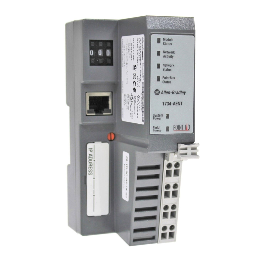
Page 25: Identify Adapter Components
What This Chapter Contains Identify Adapter Components Install the Adapter This chapter describes how to physically install the adapter on the DIN rail and connect it to the EtherNet/IP network. The following table lists where to find specific information. Topic Identify Adapter Components Mount the Adapter on a DIN Rail Before Installing Modules... -
Page 26: Mount The Adapter On A Din Rail Before Installing Modules
Install the Adapter Mount the Adapter on a DIN Rail Before Installing Modules Publication 1734-UM011D-EN-P - May 2011 Use the following procedure to mount the adapter on a new system before you install any I/O modules. 1. Position the adapter vertically above the DIN rail. 2. -
Page 27: Mount Or Replace The Adapter To An Existing System
Mount or Replace the Adapter to an Existing System Follow these steps to mount or replace an adapter. 1. Remove the existing adapter (if there is one) from the DIN rail as follows: a. Pull up on the RTB removal handle to remove the terminal block. b. -
Page 28: Wire Your Adapter
Install the Adapter Wire Your Adapter Publication 1734-UM011D-EN-P - May 2011 Refer to the illustration to wire the adapter. If you connect or disconnect wiring while the field-side power is WARNING on, an electrical arc can occur. This could cause an explosion in hazardous location installations. -
Page 29: Mounting Dimensions
Mounting Dimensions Refer to the figure for mounting dimensions. millimeters (inches) 36.51 (1.44) A = DIN rail B = Secure DIN rail approximately every 200 mm (7.8 in.) Install the Adapter 54.9 (2.16) 76.5 (3.0) 133.4 (5.25) 43520 1734-AENT 76.2H x 54.9W x 133.4D (3.0H x 2.16W x 5.25D) Publication 1734-UM011D-EN-P - May 2011... - Page 30 Install the Adapter Notes: Publication 1734-UM011D-EN-P - May 2011...
- Page 31 What This Chapter Contains Configure the Adapter for Your EtherNet/IP Network Before using your adapter in an EtherNet/IP network, configure it with an IP address, subnet mask, and optional Gateway address. This chapter describes these configuration requirements and the procedures for providing them. Here are ways you can do this: •...
-
Page 32: Configuration Requirements
Configure the Adapter for Your EtherNet/IP Network Configuration Requirements Publication 1734-UM011D-EN-P - May 2011 Before you can use your adapter, you must configure its IP address, its subnet mask, and, optionally, gateway address. You can use the Rockwell BootP utility, version 2.3 or later, to perform the configuration. -
Page 33: Ip Address
IP Address The IP address identifies each node on the IP network (or system of connected networks). Each TCP/IP node on a network (including the 1734-AENT adapter) must have a unique IP address. The IP address is 32 bits long and has a net ID part and Host ID part. Networks are classified A, B, C, (or other). -
Page 34: Subnet Mask
Configure the Adapter for Your EtherNet/IP Network Publication 1734-UM011D-EN-P - May 2011 When a node needs to communicate with a node on another network, a gateway transfers the data between the two networks. The figure shows gateway G connecting Network 1 with Network 2. 128.1.0.1 Network 1 128.2.0.1... -
Page 35: Set The Network Address
Set the Network Address Configure the Adapter for Your EtherNet/IP Network The new configuration is: 128.1.0.1 Network 1 128.2.64.1 128.2.64.2 Network 2.1 128.2.128.1 128.2.128.2 Network 2.2 A second network with Hosts D and E was added. Gateway G2 connects Network 2.1 with Network 2.2. Hosts D and E will use Gateway G2 to communicate with hosts not on Network 2.2. -
Page 36: Use The Rockwell Bootp/Dhcp Utility
Configure the Adapter for Your EtherNet/IP Network Use the Rockwell BootP/DHCP Utility Publication 1734-UM011D-EN-P - May 2011 The adapter reads the thumbwheel switches only when you cycle power to determine if the switches are set to a valid number. Press either the + or - buttons to change the number. - Page 37 Configure the Adapter for Your EtherNet/IP Network 2. Double-click the hardware address of the device you want to configure. You see the New Entry dialog with the device’s Ethernet Address (MAC). 3. Enter the IP Address you want to assign to the device, and click OK. The device is added to the Relation List, displaying the Ethernet Address (MAC) and corresponding IP Address, Hostname, and Description (if applicable).
-
Page 38: Save The Relation List
Configure the Adapter for Your EtherNet/IP Network Publication 1734-UM011D-EN-P - May 2011 You must have an entry for the device in the Relation List panel to re-enable DHCP. Save the Relation List You can save the Relation List to use later. To save the Relation List perform the following steps: 1. -
Page 39: Use Dhcp Software To Configure Your Adapter
Use DHCP Software to Configure Your Adapter Configure the Adapter for Your EtherNet/IP Network The Save As dialog appears. 2. Select the folder you want to save to. 3. Enter a file name for the Relation List (for example, control system configuration), and click Save. - Page 40 Configure the Adapter for Your EtherNet/IP Network Publication 1734-UM011D-EN-P - May 2011 To configure the adapter with a fixed IP address, see Configure the Adapter with Fixed IP Address on page 43. To avoid unintended control, the 1734-AENT adapter must be ATTENTION assigned a fixed IP address.
-
Page 41: Set Up The Hardware
What This Chapter Contains Set Up the Hardware Configure the Adapter for Direct Connection in RSLogix 5000 Software In this example, a ControlLogix controller communicates with POINT I/O modules via the 1734-AENT adapter using a direct connection. The adapter makes a direct connection to each of the modules referenced by the data. -
Page 42: Create The Example Application
Configure the Adapter for Direct Connection in RSLogix 5000 Software Create the Example Application Publication 1734-UM011D-EN-P - May 2011 We mounted the 1734-AENT adapter on a DIN rail in slot 0, with a 1734-OW2/C relay output module in slot 1, a 1734-OV4E/C sink output module in slot 2, and a power supply (not shown). -
Page 43: Configure The I/O
Configure the I/O Configure the Adapter for Direct Connection in RSLogix 5000 Software 2. From the File menu, select New. The New Controller dialog opens. 3. Enter an appropriate Name for the Controller, for example, POINT_IO_Controller. 4. Select the correct Version, Chassis Type, and Slot number of the Logix5555 controller, and the folder where you want to save the RSLogix 5000 file (Create In). -
Page 44: Add The Local Ethernet/Ip Bridge To The I/O Configuration
Configure the Adapter for Direct Connection in RSLogix 5000 Software Publication 1734-UM011D-EN-P - May 2011 • Add the local 1756-ENBT module to the I/O configuration. • Add the 1734-AENT adapter as a child of the 1756-ENBT module. • Add the I/O modules as children of the 1734-AENT adapter. Click the Help buttons on the configuration dialogs shown IMPORTANT in this section if you need assistance in selecting and setting... - Page 45 Configure the Adapter for Direct Connection in RSLogix 5000 Software The Select Module dialog opens. 3. Expand Communications to see the list of Communications modules. 4. Select the 1756-ENBT EtherNet/IP Bridge, and click OK. The Select Major Revision dialog opens. 5.
-
Page 46: Add The Point I/O Adapter To The I/O Configuration
Configure the Adapter for Direct Connection in RSLogix 5000 Software Publication 1734-UM011D-EN-P - May 2011 The New Module dialog opens. 6. Enter values for Name, IP Address, Slot, Electronic Keying, and Revision, noting that we used the following values: Name IP Address Slot Electronic Keying... - Page 47 Configure the Adapter for Direct Connection in RSLogix 5000 Software The Select Module dialog opens. 2. Expand Communications to see the list of Communications modules. Publication 1734-UM011D-EN-P - May 2011...
- Page 48 Configure the Adapter for Direct Connection in RSLogix 5000 Software Publication 1734-UM011D-EN-P - May 2011 3. Select the 1734-AENT/A Ethernet adapter from the list, and click OK, noting that we used these values. Name IP Address Comm Format Chassis Size Electronic Keying Revision The Slot field appears grey because the slot is automatically 0 for...
-
Page 49: Add The Point I/O Modules To The I/O Configuration
Configure the Adapter for Direct Connection in RSLogix 5000 Software The 1734-AENT adapter appears in the Ethernet folder. Add the POINT I/O Modules to the I/O Configuration You now add POINT I/O modules to the I/O Configuration List under the 1734-AENT adapter. - Page 50 Configure the Adapter for Direct Connection in RSLogix 5000 Software Publication 1734-UM011D-EN-P - May 2011 The Select Module dialog opens. 2. Expand Digital to see the list of Digital modules. 3. Select the 1734-OW2 relay output module from the list, and click OK. The New Module dialog opens.
- Page 51 Configure the Adapter for Direct Connection in RSLogix 5000 Software 4. Enter values for Name and Slot, noting that we used the following values. Name Slot 5. Choose Connection. The RPI is selectable since it is a direct connection. 6. Enter 50 for requested packet interval (RPI) to set how often you exchange data with the 1734-AENT adapter.
-
Page 52: Add The Digital Output Module
Configure the Adapter for Direct Connection in RSLogix 5000 Software Publication 1734-UM011D-EN-P - May 2011 Add the Digital Output Module 1. Right-click the 1734-AENT adapter, and select New Module. The Select Module dialog opens. 2. Expand Digital to see the list of Digital modules.. 3. - Page 53 Configure the Adapter for Direct Connection in RSLogix 5000 Software The New Module dialog opens. 5. Enter values for Name and Slot, noting we used the following. Name Slot 6. On the Connection tab, enter 10 ms as the RPI for the 1734-OV4E module.
-
Page 54: Edit The Controller Tags
Configure the Adapter for Direct Connection in RSLogix 5000 Software Edit the Controller Tags Tags created by the system Enter the new tag here Publication 1734-UM011D-EN-P - May 2011 When you add modules to the I/O configuration the system creates tags for those modules to use in the application program. -
Page 55: Create The Ladder Program
Create the Ladder Program Download the Program to the Controller Configure the Adapter for Direct Connection in RSLogix 5000 Software Next create the example ladder program to test the I/O. 1. Double-click Main Routine under the Main Program folder. 2. Enter the following ladder program using the tags previously created. 3. - Page 56 Configure the Adapter for Direct Connection in RSLogix 5000 Software Publication 1734-UM011D-EN-P - May 2011 1. From the main menu, choose Communications>Who-Active. The Who Active dialog opens. 2. Navigate to select the slot where the controller is located in the chassis. 3.
-
Page 57: Verify The Module Chassis Size
Verify the Module Chassis Size Configure the Adapter for Direct Connection in RSLogix 5000 Software 5. From the Download dialog, choose Download to see the RSLogix 5000 software dialog. 6. Notice that the 1756-ENBT Bridge is now online. If yellow triangles are present, see the following section. You have now built the I/O tree in RSLogix 5000 software, and the RSLogix 5000 software used the chassis size from the 1734-AENT General tab. - Page 58 Configure the Adapter for Direct Connection in RSLogix 5000 Software Value from RSLogix 5000 software Value stored in 1734-AENT adapter Publication 1734-UM011D-EN-P - May 2011 You see the Module Fault error code. 5. Click the Chassis Size tab. 6. Click Set Chassis Size in Module. 7.
-
Page 59: Configure The Adapter With Fixed Ip Address
Configure the Adapter with Fixed IP Address Configure the Adapter for Direct Connection in RSLogix 5000 Software Notice the chassis size in the module is modified to 3. 9. Click OK. At this point, your POINTBus status LED should be solid green. All the yellow triangles in your I/O configuration should be gone. -
Page 60: Recover From An Overloaded Adapter
Configure the Adapter for Direct Connection in RSLogix 5000 Software Recover From an Overloaded Adapter Publication 1734-UM011D-EN-P - May 2011 4. Read and acknowledge the warning. 5. Click OK. 6. Click the Refresh button to verify the changes. Each POINT I/O connection established with the 1734-AENT adapter consumes a portion of the microprocessor’s bandwidth. -
Page 61: Publication 1734-Um011D-En-P - May
What This Chapter Contains Configure the Adapter for Direct Connection and Rack Optimization in RSLogix 5000 Software This chapter guides you through the steps required to configure your POINT I/O Ethernet adapter for both direct connection and rack optimization using RSLogix 5000 software. You can mix communication formats for different I/O modules communicating through the same adapter. -
Page 62: Set Up The Hardware
Configure the Adapter for Direct Connection and Rack Optimization in RSLogix 5000 Software Set Up the Hardware Publication 1734-UM011D-EN-P - May 2011 In this example, a ControlLogix chassis contains the Logix 5555 controller in slot 1 and a 1756-ENBT bridge module in slot 3. We mounted the 1734-AENT adapter on a DIN rail in slot 0, with a 1734-OW2/C relay output module in slot 1, a 1734-OV4E/C sink output module in slot 2, and a power supply (not shown). -
Page 63: Create The Example Application
Create the Example Application Configure the Adapter for Direct Connection and Rack Optimization in RSLogix 5000 Software Perform the following steps to create the example application: 1. Start the RSLogix 5000 Enterprise Series software. You see the RSLogix 5000 main dialog. 2. -
Page 64: Configure The I/O Modules
Configure the Adapter for Direct Connection and Rack Optimization in RSLogix 5000 Software Configure the I/O Modules Publication 1734-UM011D-EN-P - May 2011 6. To use redundancy in your system, check the Redundancy Enabled checkbox so that a checkmark appears. RSLogix 5000 software, version 11 and later, includes enable redundancy. - Page 65 Configure the Adapter for Direct Connection and Rack Optimization in RSLogix 5000 Software 2. Click New Module. The Select Module dialog opens. 3. Expand Communications to see the list of Communications modules. 4. Select the 1756-ENBT EtherNet/IP Bridge, and click OK. The Select Major Revision dialog opens.
-
Page 66: Add The Point I/O Adapter To The I/O Configuration
Configure the Adapter for Direct Connection and Rack Optimization in RSLogix 5000 Software Publication 1734-UM011D-EN-P - May 2011 The Module Properties dialog opens. 6. Enter values for Name, IP Address, Slot, Electronic Keying, and Revision, noting we used the following values: Name IP Address Slot... - Page 67 Configure the Adapter for Direct Connection and Rack Optimization in RSLogix 5000 Software The Select Module dialog opens. 2. Expand Communications to see the list of Communications modules. 3. Select the 1734-AENT/A Ethernet adapter from the list, and click OK. The New Module dialog opens.
- Page 68 Configure the Adapter for Direct Connection and Rack Optimization in RSLogix 5000 Software Publication 1734-UM011D-EN-P - May 2011 4. Enter values for Name, IP Address, Comm Format, Chassis Size, Electronic Keying, and Revision, noting we used the following values. Name IP Address Comm Format Chassis Size...
-
Page 69: Add The Point I/O Module And Configure For Direction Connection
Configure the Adapter for Direct Connection and Rack Optimization in RSLogix 5000 Software 7. Verify that the requested packet interval (RPI) is appropriate for your system. You use this value for the rack-optimized connection to the I/O modules. To avoid overloading the 1734-AENT adapter, we IMPORTANT recommend that you set RPI no less than 10 ms for rack connections and 50 ms for direct connections. - Page 70 Configure the Adapter for Direct Connection and Rack Optimization in RSLogix 5000 Software Publication 1734-UM011D-EN-P - May 2011 2. Expand Digital to see the list of digital modules. 3. Select the 1734-OW2 relay output module from the list, and click OK. The New Module dialog opens.
-
Page 71: Rack Optimization
Configure the Adapter for Direct Connection and Rack Optimization in RSLogix 5000 Software The RPI is selectable, since it is a direct connection. 6. Verify that the requested packet interval (RPI) is appropriate for your system (10 ms for this example). You use this value for the rack-optimized connection to the I/O modules. - Page 72 Configure the Adapter for Direct Connection and Rack Optimization in RSLogix 5000 Software Publication 1734-UM011D-EN-P - May 2011 The Select Module dialog opens. 2. Expand Digital to see the list of digital modules available. 3. Choose the 1734-OV4E/C module, and click OK.
- Page 73 Configure the Adapter for Direct Connection and Rack Optimization in RSLogix 5000 Software The New Module dialog opens. 4. From the New Module dialog, complete the following. • Enter a value for Name. • Enter a value for Slot. • Click Change. The Module Definition dialog opens.
-
Page 74: Download The Program To The Controller
Configure the Adapter for Direct Connection and Rack Optimization in RSLogix 5000 Software Download the Program to the Controller Publication 1734-UM011D-EN-P - May 2011 The New Module Connection tab dialog opens. 8. On the Connection tab, enter 50 for the requested packet interval (RPI). 9. -
Page 75: Verify The Module Chassis Size
Verify the Module Chassis Size Configure the Adapter for Direct Connection and Rack Optimization in RSLogix 5000 Software 3. Choose Set Project Path. 4. Choose Download. You see the Download dialog. 5. From the Download dialog, click Download. You see this RSLogix 5000 dialog. 6. -
Page 76: Select Properties
Configure the Adapter for Direct Connection and Rack Optimization in RSLogix 5000 Software Value from RSLogix 5000 software Value stored in 1734-AENT adapter Publication 1734-UM011D-EN-P - May 2011 3. Select Properties. 4. Click the Connection tab. You see the Module Fault error code. 5. - Page 77 Configure the Adapter for Direct Connection and Rack Optimization in RSLogix 5000 Software 7. Read and acknowledge the warning dialog. 8. Click OK to continue. 9. Notice the chassis size in the module is modified to 3. 10. Click OK. At this point, your POINTBus status LED should be solid green.
-
Page 78: Access Module Data
Configure the Adapter for Direct Connection and Rack Optimization in RSLogix 5000 Software Access Module Data Publication 1734-UM011D-EN-P - May 2011 Use the following information to use the 1734 POINT I/O Ethernet adapter data in the ladder logic program. • POINT_IO_Adapter = the name you gave to your Ethernet adapter •... -
Page 79: What This Chapter Contains
What This Chapter Contains LED Status Indicators Read this chapter for information about LED status indicators. Interpret the Status Indicators Module Status Network Activity Network Status POINTBus Status System Power Field Power You must use series C POINT I/O modules with the ATTENTION 1734-AENT adapter. - Page 80 LED Status Indicators Publication 1734-UM011D-EN-P - May 2011 Indication Probable Cause Network Activity No link established. Flashing Transmit or receive activity green/Off present. Steady green Link established. Network Status Device not initialized. The module does not have an IP address. Flashing green No CIP connections present.
- Page 81 System Power Not active; field power is off or DC-DC converter problem present. Green System power is on; DC-DC converter is active (5V). Field Power Not active; field power is off. Green Power is on; 24V is present. LED Status Indicators 1.
- Page 82 LED Status Indicators Notes: Publication 1734-UM011D-EN-P - May 2011...
-
Page 83: What This Appendix Contains
What This Appendix Contains Work with the Home Page Adapter Web Pages Read this appendix for information about the adapter Web page diagnostics that offer extensive internal and network diagnostics. Topic Work with the Home Page Work with the Diagnostics Pages Work with the Configuration Pages Work with the Browse Chassis Page Use the adapter diagnostics Home page to access other adapter diagnostics... - Page 84 Adapter Web Pages Enter the adapter IP address to see the Home page. Click Expand to expand options. Publication 1734-UM011D-EN-P - May 2011 You must use Series C POINT I/O modules with the 1734-AENT ATTENTION adapter. Series A or B POINT I/O modules will not work with this adapter.
-
Page 85: Work With The Diagnostics
Work with the Diagnostics Pages Click tabs to see the corresponding page. Click from this panel to see the corresponding page. 3. From the Home page, complete one of these, as desired. • Click one of these to go to http://www.ab.com/. –... -
Page 86: Use The Diagnostic Overview Page
Adapter Web Pages Publication 1734-UM011D-EN-P - May 2011 Use the Diagnostic Overview Page To use the Diagnostic Overview page to view general diagnostics information, follow this procedure. 1. From the Web page, click the Diagnostic Overview tab at the top of the page or panel on the left. -
Page 87: Use The Network Settings Page
– Open Errors – Conn Closes – Close Errors – Conn Timeout – Status • Module Settings – Chassis Size – Switches Use the Network Settings Page To use the Network Settings page to view network related information, follow this procedure. 1. -
Page 88: Use The Ethernet Statistics Page
Adapter Web Pages Publication 1734-UM011D-EN-P - May 2011 2. From the Network Settings page, view the following. • Network Interface – Ethernet Address (MAC) – IP Address – Subnet Mask – Default Gateway – Primary Name Server – Secondary Name Server –... - Page 89 The Ethernet Statistics tab opens. 2. From the Ethernet Statistics tab, view the following: • Ethernet Link – Media Speed, Half or Full Duplex, Autonegotiate Status • Interface Counters – In Octets, In UCast Packets, In NUcast Packets, In Discards, In Errors, In Unknown Protos, Out Octets, Out Ucast Packets, Out NUcast Packets, Out Discards, Out Errors •...
-
Page 90: Use The I/O Connections Page
Adapter Web Pages Publication 1734-UM011D-EN-P - May 2011 Use the I/O Connections Page To use the I/O Connections page to view CIP I/O (Class 1) connection information, follow this procedure. 1. From the Web page, click the I/O Connections tab at the top of the page or panel on the left. -
Page 91: Use The Diagnostic Messaging Page
Use the Diagnostic Messaging Page To use the Diagnostic Messaging page to execute explicit, unconnected message services, use this procedure. 1. From the Web page, click the Diagnostic Messaging tab at the top of the page or panel on the left. The Diagnostic Messaging tab opens. -
Page 92: Work With The Configuration
Adapter Web Pages Work with the Configuration Pages Publication 1734-UM011D-EN-P - May 2011 3. From the Diagnostic Messaging tab, click Submit to see values similar to that in the figure. To work with the Configuration pages, follow these procedures, noting that values on these pages are stored in and retrieved from non-volatile memory. -
Page 93: Use The Identity Page
2. From the Configuration page, click one of these. • Identity • Network • Services The Enter Network Password dialog opens. 3. From the user name and password dialog, enter values, noting the following. • The values for user name and password are case sensitive. •... -
Page 94: Use The Network Configuration Page
Adapter Web Pages Publication 1734-UM011D-EN-P - May 2011 You see the Identity page. 2. From the Identity tab, complete entries for the following, noting that the description and location help you identify where modules are in the facility. • Host Name – the name a Domain Name Server uses to resolve this adapter’s IP address •... - Page 95 You see the Network Configuration page. 2. From the Network Configuration tab, complete these entries, noting that values for Network Interface are disabled when DHCP is Dynamic DHCP and port speed and duplex mode are disabled when Autonegotiate Speed and Duplex is selected. •...
-
Page 96: Use The Services Page
Adapter Web Pages Work with the Browse Chassis Page Publication 1734-UM011D-EN-P - May 2011 Use the Services Page To use the Services page to change the password for the Configuration web page or disable the Web server, complete these procedures. 1. - Page 97 To work with the Browse Chassis page, follow these procedures. Check Increase timeout to increase the time of the browse query and time the modules get to respond to the query, which is useful when browsing a busy system. Before the query completes, this note...
- Page 98 Adapter Web Pages Publication 1734-UM011D-EN-P - May 2011 After completion of a query, here is how a typical Browse Chassis page looks with the module hyperlinks active and the Display compact check box unchecked. Click a module hyperlink to view information about the module.
- Page 99 Adapter Web Pages • Module Revision • Serial Number • Status Publication 1734-UM011D-EN-P - May 2011...
- Page 100 Adapter Web Pages Notes: Publication 1734-UM011D-EN-P - May 2011...
-
Page 101: What This Appendix Contains
What This Appendix Contains Install the RSLinx Software Configure the RSLinx Ethernet Communication Driver To communicate with your 1734-AENT adapter over your network you must configure the RSLinx EtherNet/IP driver (AB_ETH/IP). You need one of these drivers to download the example application programs in this manual. See the table for a list of the contents of this appendix and where to find specific information: Topic... -
Page 102: Configure The Ab_Eth/Ip Driver
Configure the RSLinx Ethernet Communication Driver Configure the AB_ETH/IP Driver Publication 1734-UM011D-EN-P - May 2011 To configure the AB_ETH/IP Ethernet communication driver, perform the following steps. 1. Start RSLinx software. 2. From the Communications menu, select Configure Drivers. 3. Click the arrow to the right of the Available Driver Types box. The Available Driver Types list appears. - Page 103 Configure the RSLinx Ethernet Communication Driver 5. Make sure the Browse Local Subnet button is selected. RSLinx software browses your local subnet and automatically reads the IP address. 6. Click OK. The AB_ETH/IP driver is now configured and appears in the configured drivers window.
- Page 104 Configure the RSLinx Ethernet Communication Driver Notes: Publication 1734-UM011D-EN-P - May 2011...
-
Page 105: What This Appendix Contains
What This Appendix Contains 1734 POINT I/O Catalog Numbers POINT I/O Module and RSLogix 5000 Software Controller Tag Reference Read this appendix for information about tag references. You must use series C POINT I/O modules with the 1734-AENT ATTENTION adapter. Series A or B POINT I/O modules will not work with this adapter. -
Page 106: Valid Number Ranges For Rslogix 5000 Data Types
POINT I/O Module and RSLogix 5000 Software Controller Tag Reference Valid Number Ranges for RSLogix 5000 Data Types Publication 1734-UM011D-EN-P - May 2011 1734 POINT I/O RSLogix5000 Module Description Catalog Number Specialty I/O 1734-232ASC/C 1 Channel ASCII Interface Module 1734-IJ/C 1 Channel 5V DC Encoder/Counter 1734-IK/C 1 Channel 15…24V DC Encoder/Counter... -
Page 107: Digital 2 Point Input
Digital 2 POINT Input POINT I/O Module and RSLogix 5000 Software Controller Tag Reference 1734-IA2 2 POINT 120V AC Input 1734-IB2 2 POINT 10…28V DC Input, Sink 1734-IM2 2 POINT 240V AC Input 1734-IV2 2 POINT 10…28V DC Input, Source Configuration Data Data Type Filter Off On Time - POINT 0... - Page 108 POINT I/O Module and RSLogix 5000 Software Controller Tag Reference Digital 4 POINT Input Publication 1734-UM011D-EN-P - May 2011 1734-IB4 4 POINT 10…28V DC Input, Sink 1734-IV4 4 POINT 10…28V DC Input, Source Configuration Data Data Type Filter Off On Time - POINT 0 Filter On Off Time - POINT 0 Filter Off On Time - POINT 1 Filter On Off Time - POINT 1...
- Page 109 Digital 2 POINT Output – Without Diagnostic Status POINT I/O Module and RSLogix 5000 Software Controller Tag Reference 1734-OA2 2 POINT 120V AC Output 1734-OW2 2 POINT AC/DC Relay Output 1734-OX2 2 POINT Relay Output N.O./N.C. Configuration Data Data Type Fault Mode - POINT 0, 1 SINT, BIT Fault Value - POINT 0, 1...
-
Page 110: Digital 2 Point Output - With Over Load And Open Load Diagnostic Status
POINT I/O Module and RSLogix 5000 Software Controller Tag Reference Digital 2 POINT Output – With Over Load and Open Load Diagnostic Status Publication 1734-UM011D-EN-P - May 2011 1734-OB2E 2 POINT 10…28V DC Electronically Fused Output, Source 1734-OB2EP 2 POINT 10…28V DC Electronically Fused Protected Output, Source Configuration Data Data Type Fault Mode - POINT 0, 1... - Page 111 Digital 2 POINT Output – With Over Load Diagnostic Status POINT I/O Module and RSLogix 5000 Software Controller Tag Reference 1734-OV2E 2 POINT 10…28V DC Electronically Fused Output, Sink Configuration Data Data Type Fault Mode - POINT 0, 1 SINT, BIT Fault Value - POINT 0, 1 SINT, BIT Program Mode - POINT 0, 1...
-
Page 112: Digital 4 Point Output - With Over
POINT I/O Module and RSLogix 5000 Software Controller Tag Reference Digital 4 POINT Output – With Over Load and Open Load Diagnostic Status Publication 1734-UM011D-EN-P - May 2011 1734-OB4E 4 POINT 10…28V DC Electronically Fused Output, Source Configuration Data Fault Mode - POINT 0, 1, 2, 3 Fault Value - POINT 0, 1, 2, 3 Program Mode - POINT 0, 1, 2, 3 Program Value - POINT 0, 1, 2, 3... -
Page 113: Load Diagnostic Status
Digital 4 POINT Output – With Over Load Diagnostic Status POINT I/O Module and RSLogix 5000 Software Controller Tag Reference 1734-OV4E 4 POINT 10…28V DC Electronically Fused Output, Sink Configuration Data Fault Mode - POINT 0, 1, 2, 3 Fault Value - POINT 0, 1, 2, 3 Program Mode - POINT 0, 1, 2, 3 Program Value - POINT 0, 1, 2, 3 Auto Restart Enable - POINT 0, 1, 2, 3... - Page 114 POINT I/O Module and RSLogix 5000 Software Controller Tag Reference Analog 2 Channel Input Publication 1734-UM011D-EN-P - May 2011 1734-IE2C 2 Channel Analog Current Input Configuration Data Low Engineering Channel 0 High Engineering Channel 0 Digital Filter Channel 0 Low Alarm Limit Channel 0 High Alarm Limit Channel 0 Low Low Alarm Limit Channel 0 High High Alarm Limit Channel 0...
- Page 115 POINT I/O Module and RSLogix 5000 Software Controller Tag Reference 1734-IE2C 2 Channel Analog Current Input Input Data Data Type Data Channel 0 Data Channel 1 Status Byte Channel 0 SINT Status Byte Channel 1 SINT Output Data Data Type None Default Valid Data Values...
- Page 116 POINT I/O Module and RSLogix 5000 Software Controller Tag Reference Publication 1734-UM011D-EN-P - May 2011 1734-IE2V 2 Channel Analog Voltage Input Configuration Data Low Engineering Channel 0 High Engineering Channel 0 Digital Filter Channel 0 Low Alarm Limit Channel 0 High Alarm Limit Channel 0 Low Low Alarm Limit Channel 0 High High Alarm Limit Channel 0...
- Page 117 POINT I/O Module and RSLogix 5000 Software Controller Tag Reference 1734-IE2V 2 Channel Analog Voltage Input Input Data Data Type Data Channel 0 Data Channel 1 Status Byte Channel 0 SINT Status Byte Channel 1 SINT Output Data Data Type None Default Valid Data Values...
- Page 118 POINT I/O Module and RSLogix 5000 Software Controller Tag Reference Publication 1734-UM011D-EN-P - May 2011 1734-IR2 2 Channel RTD Input Configuration Data Data Type Low Engineering Channel 0 High Engineering Channel 0 Digital Filter Channel 0 Low Alarm Limit Channel 0 High Alarm Limit Channel 0 Low Low Alarm Limit Channel 0 High High Alarm Limit Channel 0 INT...
- Page 119 POINT I/O Module and RSLogix 5000 Software Controller Tag Reference 1734-IR2 2 Channel RTD Input Configuration Data Data Type Sensor Type Channel 1 SINT Temperature Mode Channel 1 SINT Notch Filter (Channel 0 & 1) SINT Input Data Data Type Data Channel 0 Data Channel 1 Status Byte Channel 0...
- Page 120 POINT I/O Module and RSLogix 5000 Software Controller Tag Reference Publication 1734-UM011D-EN-P - May 2011 1734-IT2 2 Channel Thermocouple Input, Isol. Configuration Data Data Type Cold Junction Notch Filter SINT Cold Junction Mode SINT Low Engineering Channel 0 High Engineering Channel 0 Alarm Disable Channel 0 SINT Limit Alarm Latch Channel 0...
- Page 121 POINT I/O Module and RSLogix 5000 Software Controller Tag Reference 1734-IT2 2 Channel Thermocouple Input, Isol. Configuration Data Data Type Temperature Mode Channel 0 SINT Cold Junction Enable Channel 0 SINT Cold Junction Offset Channel 0 Low Engineering Channel 1 High Engineering Channel 1 Alarm Disable Channel 1 SINT...
- Page 122 POINT I/O Module and RSLogix 5000 Software Controller Tag Reference Publication 1734-UM011D-EN-P - May 2011 1734-IT2 2 Channel Thermocouple Input, Isol. Configuration Data Data Type Temperature Mode Channel 1 SINT Cold Junction Enable Channel 1 SINT Cold Junction Offset Channel 1 Input Data Data Type Data Channel 0...
-
Page 123: Analog 2 Channel Output
Analog 2 Channel Output POINT I/O Module and RSLogix 5000 Software Controller Tag Reference 1734-OE2C 2 Channel Analog Current Output Configuration Data Data Type Fault Value Channel 0 Program Value Channel 0 Low Engineering Channel 0 High Engineering Channel 0 Low Limit Channel 0 High Limit Channel 0 Range Type Channel 0... - Page 124 POINT I/O Module and RSLogix 5000 Software Controller Tag Reference Publication 1734-UM011D-EN-P - May 2011 1734-OE2C 2 Channel Analog Current Output Configuration Data Data Type Idle Mode Channel 1 SINT Limit Alarm Latch Channel 1 SINT Alarm Disable Channel 1 SINT Input Data Data Type...
- Page 125 POINT I/O Module and RSLogix 5000 Software Controller Tag Reference 1734-OE2V 2 Channel Analog Voltage Output Configuration Data Data Type Fault Value Channel 0 Program Value Channel 0 Low Engineering Channel 0 High Engineering Channel 0 Low Limit Channel 0 High Limit Channel 0 Range Type Channel 0 SINT...
- Page 126 POINT I/O Module and RSLogix 5000 Software Controller Tag Reference Publication 1734-UM011D-EN-P - May 2011 1734-OE2V 2 Channel Analog Voltage Output Configuration Data Data Type Limit Alarm Latch Channel 1 SINT Alarm Disable Channel 1 SINT Input Data Data Type Status Byte Channel 0 SINT Status Byte Channel 1...
- Page 127 Specialty I/O POINT I/O Module and RSLogix 5000 Software Controller Tag Reference 1734-VHSC24 1 Channel 15…24V DC Very High-speed Counter 1734-VHSC5 1 Channel 5V DC Very High-speed Counter Configuration Data Data Type Default Counter Config SINT Config_0 BIT 0 Config_1 BIT 1 Config_2 BIT 2...
- Page 128 POINT I/O Module and RSLogix 5000 Software Controller Tag Reference Publication 1734-UM011D-EN-P - May 2011 1734-VHSC24 1 Channel 15…24V DC Very High-speed Counter 1734-VHSC5 1 Channel 5V DC Very High-speed Counter Configuration Data Data Type Default Scalar SINT Output Ties 0 SINT Out 0 Window 1 BIT 0...
- Page 129 POINT I/O Module and RSLogix 5000 Software Controller Tag Reference 1734-VHSC24 1 Channel 15…24V DC Very High-speed Counter 1734-VHSC5 1 Channel 5V DC Very High-speed Counter Configuration Data Data Type Default SS Output Control SINT SS Out 0 Force BIT 0 SS Out 0 En BIT 1 SS Out 0 Electronic Fuse...
- Page 130 POINT I/O Module and RSLogix 5000 Software Controller Tag Reference 1734-VHSC24 1 Channel 15…24V DC Very High-speed Counter 1734-VHSC5 1 Channel 5V DC Very High-speed Counter Input Data Present Data Stored Data Status Zero Frequency Detected Stored Data Count_2 Stored Data Count_3 A Input Status B Input Status Z Input Status...
- Page 131 POINT I/O Module and RSLogix 5000 Software Controller Tag Reference Stored Data To interpret values from -2,147,483,648 to -1, use this conversion formula: Stored Data Tag Value + 4,294,967,296 = Actual Stored Data Tag Value. As an example, for a read value of -1,794,967,296: -1,794,967,296 + 4,294,967,296 = 2,500,000,000 actual value Program Fault Programming Fault Error bit –...
- Page 132 POINT I/O Module and RSLogix 5000 Software Controller Tag Reference 1734-VHSC24 1 Channel 15…24V DC Very High-speed Counter 1734-VHSC5 1 Channel 5V DC Very High-speed Counter Output Data PWM Value Counter Control Value Reset Output Control Publication 1734-UM011D-EN-P - May 2011 Data Type SINT Counter Reset...
- Page 133 POINT I/O Module and RSLogix 5000 Software Controller Tag Reference 1734-IJ 1 Channel 5V DC Encoder / Counter 1734-IK 1 Channel 15…24V DC Encoder / Counter Configuration Data Data Type Counter Config SINT Config_0 BIT 0 Config_1 BIT 1 Config_2 BIT 2 Config_3 BIT 3...
- Page 134 POINT I/O Module and RSLogix 5000 Software Controller Tag Reference 1734-IJ 1 Channel 5V DC Encoder / Counter 1734-IK 1 Channel 15…24V DC Encoder / Counter Configuration Data SS Counter Control Publication 1734-UM011D-EN-P - May 2011 Data Type SINT SS Counter Reset BIT 0 SS Counter Preset BIT 1...
-
Page 135: Stored Data
POINT I/O Module and RSLogix 5000 Software Controller Tag Reference 1734-IJ 1 Channel 5V DC Encoder / Counter 1734-IK 1 Channel 15…24V DC Encoder / Counter Input Data Data Type Present Data DINT Stored Data DINT Status Zero Frequency Detected BIT 1 Stored Data Count_2 BIT 2... - Page 136 POINT I/O Module and RSLogix 5000 Software Controller Tag Reference 1734-IJ 1 Channel 5V DC Encoder / Counter 1734-IK 1 Channel 15…24V DC Encoder / Counter Output Data Counter Control Publication 1734-UM011D-EN-P - May 2011 Program Fault Note Programming Fault Error bit – If an incomplete, incorrect, or conflicting set of configuration parameters is sent to the module, the Program Fault bit is asserted and an error code placed in the Programming Error Code word (assembly 6816).
- Page 137 POINT I/O Module and RSLogix 5000 Software Controller Tag Reference 1734-SSI 1 Channel Synchronous Serial Interface Configuration Data Data Type SINT Gray Binary SINT Word Length SINT Data Speed SINT G2B Convert (Gray to Binary) SINT Standardization SINT (Divide / Shift using Trailing) SSI Word Delay Time Trailing (No.
- Page 138 POINT I/O Module and RSLogix 5000 Software Controller Tag Reference Publication 1734-UM011D-EN-P - May 2011 SSI Word Delay Time To enter Delay values from +32,768…+65,535 µs, use this conversion formula: Desired Delay Value (in µs) - 65536 = Entered Delay Value (in µs). As an example, for a 40 ms delay time, 40000 - 65536 = -25536 Sensor Resolution To enter Resolution values from +32,768…+65,535 µs, use this conversion...
- Page 139 POINT I/O Module and RSLogix 5000 Software Controller Tag Reference 1734-SSI 1 Channel Synchronous Serial Interface Input Data Data Type Present Data DINT Latched Data DINT Status Input Status BIT 0 BIT 1 Decreasing Count BIT 2 Increasing Count BIT 3 BIT 4 Compare0 Reached Compare1 Reached...
- Page 140 POINT I/O Module and RSLogix 5000 Software Controller Tag Reference Publication 1734-UM011D-EN-P - May 2011 1734-SSI 1 Channel Synchronous Serial Interface Output Data Data Type Control SINT Latch Acknowledge BIT 0 Compare 0 Acknowledge BIT 1 Compare 1 Acknowledge BIT 2 Compare 0 Select BIT 3 Compare 1 Select...
- Page 141 POINT I/O Module and RSLogix 5000 Software Controller Tag Reference 1734-232ASC 1 Channel ASCII Interface Module Configuration Data Data Type Serial Character Format SINT (ASCII Format: Data Bits / Parity / Stop) Serial Comm Speed SINT (Communication Rate of the Serial Port) Max Receive Characters SINT Receive Start Delimiter Mode...
- Page 142 POINT I/O Module and RSLogix 5000 Software Controller Tag Reference 1734-232ASC 1 Channel ASCII Interface Module Configuration Data Transmit End Delimiter Mode Transmit End Delimiter Character Consume String Data Type Transmit Swap Mode DeviceNet Record Header Mode Publication 1734-UM011D-EN-P - May 2011 Data Type SINT SINT...
- Page 143 POINT I/O Module and RSLogix 5000 Software Controller Tag Reference 1734-232ASC 1 Channel ASCII Interface Module Input Data Data Type Receive Record Number SINT Status SINT TX FIFO Overflow BIT 0 RX FIFO Overflow BIT 1 RX Parity Error BIT 2 Handshake Error BIT 6 New Data Flag...
- Page 144 POINT I/O Module and RSLogix 5000 Software Controller Tag Reference Publication 1734-UM011D-EN-P - May 2011 Transmit Record Number/ Receive Record Number / Length_Lo Note that 7 data bits allows Transmit / Receive record Number of Length_Lo values of 0…127, which RSLogix 5000 software does support in the signed Short Integer data type SINT (-128…+127 range).
-
Page 145: What This Appendix Contains
What This Appendix Contains Quick Start In this quick start, you learn how to use the 1734-AENT adapter with a ControlLogix controller for EtherNet/IP systems. This quick start contains a simple set of steps and IMPORTANT reminders that will help you avoid errors when you are configuring your POINT I/O system for and EtherNet/IP network. -
Page 146: Configure The Adapter
Quick Start Configure the Adapter Publication 1734-UM011D-EN-P - May 2011 In the 1734-AENT Module Properties dialog, perform the following steps. 1. Complete the Name field. 2. Enter the following address into the IP Address field: 192.168.1.42 You are setting the last digit, because the first three digits are set for you as set by the push wheel switches on the adapter. -
Page 147: Enter Adapter Properties
Enter Adapter Properties Use this procedure to enter adapter properties. 1. Right-click the 1734-AENT adapter and select Properties. The Module Properties dialog appears. 2. Click the Chassis Size tab. Notice that the data under this tab is dimmed while offline. Use the Chassis Size tab to send the module size from the General tab to the module itself once you are online. -
Page 148: Add Another Module Under The Adapter
Quick Start Publication 1734-UM011D-EN-P - May 2011 5. In the Module Properties dialog, enter the following information. a. Name b. Slot c. Comm Format d. Electronic Keying, choose Compatible Module to verify the major revision C, because only series C modules support EtherNet/IP. e. -
Page 149: Configure 1734 Point I/O Modules
Configure 1734 POINT I/O Modules For RSLogix 5000 software version 13 and earlier, configure your POINT I/O modules via the Controller Tags database, using the following steps. For RSLogix 5000 software, versions 15 or later, the preferred method for module configuration is to use the Module Properties dialog for each POINT I/O module, as described in the individual user manual for the module. - Page 150 Quick Start Publication 1734-UM011D-EN-P - May 2011 • 2 = 0…10V DC • 0 = -10…+10V DC 5. Click the value 2 and change it to 0, which changes the voltage range to -10…+10V DC for channel 0. Note the following: •...
- Page 151 – If you downloaded the offline configuration into the module and then realize that you must modify any of the module’s configuration parameters, then the preferred way to make these changes online is to go to the Module Connection tab and inhibit the module, apply the changes, and then uninhibit the module.
-
Page 152: Publication 1734-Um011D-En-P - May
Quick Start Configure an Ethernet Driver in RSLinx Software Publication 1734-UM011D-EN-P - May 2011 Now you can put your controller in Run mode, and the connection should be successful. The information found in the Controller Tag Reference IMPORTANT section of this user manual is also available in the RSLogix 5000 online help file. - Page 153 The Rockwell Software RSLinx Gateway - [RSWho - 1] screen appears. The RSWho screen is actually RSLinx’s network browser interface, which lets you view all of your active network connections. The left pane of this display is the Tree Control, which shows networks and devices in a hierarchical view.
- Page 154 Quick Start Publication 1734-UM011D-EN-P - May 2011 Add the AB_ETHIP-1 (EtherNet/IP) Driver 1. From the Communications menu, choose Configure Drivers. The Configure Drivers dialog appears. 2. From the Available Driver Types pull-down menu, choose EtherNet/IP Driver. 3. Click the Add New button. 4.
- Page 155 Numerics 1734-POINT I/O catalog numbers AB-ETHIP driver access module data adapter features replacing on system wiring auto negotiate autobaud bandwidth, insufficient BootP/DHCP utility browse chassis page catalog numbers chassis size CIP Common Industrial Protocol Common Industrial Protocol (CIP) compatibility hardware and software configuration configure adapter for direct connection and rack...
- Page 156 Index power up system for the first time producer/consumer model understanding program fault note publications related quick start rack optimized connection recover from an overloaded adapter reinsertion of modules relation list removal of modules replace adapter on system replacement of adapter requested packet interval (RPI) RIUP remove and replace under power Rockwell BootP/DHCP utility...
-
Page 158: Rockwell Automation Support
Rockwell Automation Support Rockwell Automation provides technical information on the Web to assist you in using its products. http://www.rockwellautomation.com/support/ and application notes, sample code and links to software service packs, and a MySupport feature that you can customize to make the best use of these tools. For an additional level of technical phone support for installation, configuration, and troubleshooting, we offer TechConnect support programs.
Need help?
Do you have a question about the Rockwell Automation 1734-AENT and is the answer not in the manual?
Questions and answers