
Related Manuals for Thermo Scientific IMP 180


Summary of Contents for Thermo Scientific IMP 180
- Page 2 Trademarks Heratherm™ is a registered trademark of Thermo Scientific. Thermo Scientific is a brand owned by Thermo Fisher Scientific, Inc. All other trademarks mentioned in the operating instructions are the exclusive property of the respective manufacturers. Thermo Fisher Scientific Robert-Bosch-Straße 1...
- Page 3 Basic Operating Precautions ....................... 1-1 Operational Safety Rules ........................1-2 Warranty ............................1-2 Explanation of Safety Information and Symbols ................. 1-3 Safety Notes and Symbols Used Throughout These Operating Instructions ........1-3 Additional Symbols for Safety Information..................1-4 Symbols on the refrigerated incubator .................... 1-5 Intended Purpose of the refrigerated incubator ...................
- Page 4 Alarm Contact..........................4-9 AC Power Socket..........................4-9 Fuses............................... 4-9 Work Space Components ......................... 4-11 Inner Chamber ..........................4-11 Access Port (Option) ........................4-11 Shelf System ..........................4-12 Additional Tube Access Port (Option) ..................... 4-13 Table-top refrigerated incubators......................5-1 Installing the Shelf System ........................5-1 Initial Installation ...........................
- Page 5 Temperature Display Unit ......................7-20 TWB Setting/Activating (adjustable temperature) .................7-21 Program Preferences ........................7-22 Configuration..........................7-25 Programming ............................7-26 End of Program..........................7-26 Instructions ...........................7-26 Shutting the refrigerated incubator Down ...................8-1 Cleaning..............................9-1 Cleaning Exterior Surfaces.......................9-1 Wipe / Spray Disinfection ........................9-1 Preparing the Manual Wipe/Spray Disinfection ................9-2 Pre-disinfection ..........................9-3 Cleaning............................9-4 Final Disinfection..........................9-4...
- Page 7 Figure 3-2 Floor stand refrigerated incubators, dimensions and required clearances ..........3-4 Figure 3-3 Lift Points............................. 3-5 Figure 4-1 Heratherm IMP 180 Front View ......................4-2 Figure 4-2 Heratherm IMP 180 Rear View......................4-3 Figure 4-3 Heratherm IMP 400-S Front View....................... 4-4 Figure 4-4 Heratherm IMP 400-S Rear View ......................
- Page 9 These operating instructions describe Heratherm refrigerated incubators. Heratherm refrigerated incubators have been manufactured to the latest state of the art and have been tested thoroughly for flawless functioning prior to shipping. However, the refrigerated incubator may present potential hazards, particularly if it is operated by inadequately trained personnel or if it is not used in accordance with the intended purpose.
- Page 10 • the refrigerated incubator is not modified, • only original spare parts and accessories that have been approved by Thermo Scientific are used (third-party spares without Thermo Scientific approval void the limited warranty), •...
- Page 14 Heratherm refrigerated incubators are laboratory equipment for tempering (cooling and heating) of defined substances and materials. They serve for the preparation and cultivation of cell and tissue cultures. The devices employ precision temperature control for simulating the particular physiological environment for these cultures. To avoid the risk of explosion do not load the refrigerated incubator with tissue, material, or liquids that: •...
- Page 15 • completeness, • possible damage. If components are missing or damage is found on the refrigerated incubator or the packaging, in particular damage caused by humidity and/or water, please notify the carrier as well as Thermo Scientific Technical Support immediately.
- Page 16 Support rail for shelf table-top refrigerated incubators Shelf support Power cord Connector, potential-free contact Clip springs for table-top refrigerated incubators Plug for standard access port Anti-tilt anchor Operating manual Summarized Safety Instructions Condensed water dish IMP 180 Condensed water dish IMP 400...
- Page 17 The refrigerated incubator must only be operated in a location that meets all of the ambient condition requirements listed below: • Installation location indoors in dry areas free from drafts. • The dust burden may not exceed the contamination category 2 based on EN 61010-1. Using the refrigerated incubator in an atmosphere with electrically conductive dust is prohibited.
- Page 18 • Relative humidity up to 70%, non condensing, at an ambient temperature of 28°C. • Should condensation exist, wait until the moisture has evaporated completely before connecting the refrigerated incubator to a power source and powering up. • Consider installing one dedicated upstream circuit breaker per refrigerated incubator to avoid multiple device failures in case of an electrical fault.
- Page 19 When installing the refrigerated incubator, make sure that the installation and supply connections remain freely accessible. The specified side clearances represent minimum distances. * Depth of handle /display (66 mm/2.6 in) not included in overall depth specified; height of adjustable feet (36 mm/1.4 in) not included in overall height specified.
- Page 20 Depth of handle /display (66 mm/2.6 in) not included in overall depth specified. Width of hinge (23 mm/0,91 in) not included in overall width.
- Page 21 For transport, do not lift the refrigerated incubator using the doors or components attached to the refrigerated incubator as lift points.
- Page 22 The floor stand refrigerated incubators come equipped with four (4) casters. The lever for releasing the caster is located above the locking lever. After positioning the unit in its installation location ensure that the locking levers are pressed down on the casters. To ensure the degree of stability specified by safety requirements the front casters must be turned so that they are facing forward after the unit has been positioned in its installation location and the locking levers pressed down on these casters.
- Page 23 Two IMP 180 can be stacked without use of a stacking kit. The kit is recommended when stacking with an oven or a unit with decontamination cycle, to avoid temperature impact. 2 x Anti-tilt anchor Two IMP 180 can be stacked without use of a stacking kit. The kit is recommended when stacking with an oven or a unit with decontamination cycle, to avoid temperature impact.
- Page 24 The Heratherm table-top refrigerated incubators must be secured with anti-tilt anchors witch are connected a solid part of a building. The anti-tilt anchor is to be mounted in the middle position (2) or if not possible on the side opposite of the door hinges. Bend the fixing tabs of the anti-tilt anchor up on one side and down on the other by an angle of approx.
- Page 25 Heratherm floor stand refrigerated incubators must always be attached to the wall using two (2) retaining brackets on the outer left and right side on the back of the unit. When operating under maximum environment- and condition of employment and when using low setpoint temperature can lead to performance losses in stacked devices.
- Page 26 Additionally, the following caution notes must be heeded at all times:...
- Page 27 IMP Series advanced protocol microbiological refrigerated incubators come equipped with the following features: • high-precision work space temperature control, adjustable in steps of one-tenth of a degree from 5°C (32°F) up to 70°C (158°F) • Peltier-air-air-system with work space and outside fan •...
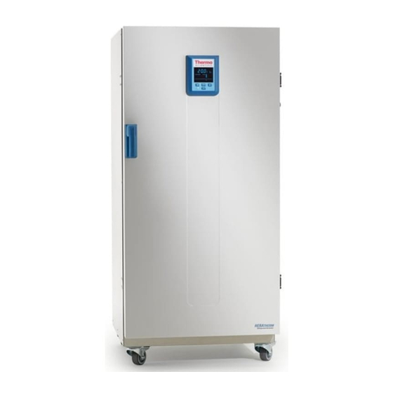
- Page 28 The individual features of IMP Series refrigerated incubators are shown in the figures below. Outer door Door latch cutout Door latch and handle Door hinge, lower Leveling foot Nameplate Temperature sensor Support rail for perforated shelf Shelf support [10] Fan opening, air baffle [11] Door hook catch [12] Air baffle [13] Door seal...
- Page 29 Door latch and handle Control panel Stacking pad Access port Peltier system with outside fan Electronics compartment Leveling foot Sample sensor connection Condense water drain with dish [10] Electro compartment...
- Page 30 Outer door Door latch Unit caster Air baffle Perforated shelf Door hook catch Glass door latch Temperature sensor Access port [10] Glass door [11] Fan opening, air baffle [12] Door frame heater...
- Page 31 Outer door Unit caster 2 x condensate water drain with dish Access port Anti-tilt anchor Electronics compartment Hinge Door handle Display [10] Nameplate on sidewall [11] 2 x Peltier system with outside fan...
- Page 32 The installed "Peltier -air-air system" (see Figure 4-5 and 4-6) is integrated in the rear wall and designed for tempering (cooling and heating) of the usable space. The Peltier module consists of two heat sinks (heat exchanger), each equipped with an axial fan. In cooling mode, heat from the usable space is absorbed and conducted to the environment on the device outside.
- Page 33 The refrigerated incubators are equipped with the following safety features: • a sample protection feature that safeguards the samples against destruction through overheating in case of controller failure; • dual sensor: if one sensor fails, the other will take over. •...
- Page 34 The work space temperature sensor provides the inputs to the refrigerated incubator’s built-in controller, which continuously compares the measured values to the user-specified set value and adjusts the heaters according to the result. The unit has a thermal protection function that is factory-preprogrammed and not adjustable. It protects the cultures in the work space from overheating: Thermal protection kicks in on a brief violation of the upper limit, based on the defined setpoint temperature, at between 2 and 3 °C (35.6 °F and 37.4 °F) (37 °C (99 °F): 2 °C (35.6 °F), >...
- Page 35 All signal connections are installed in the electrical interface panel at the rear of the refrigerated incubator. The RS- 232 interface (item 2 in figure 4-9 below) may be used to connect Heratherm refrigerated incubators to the serial interface port of a computer to allow for the computer-aided acquisition and documentation of major operating parameters (temperature, error codes, etc.).
- Page 36 Access to the 2 A fuses for the electrical outlets Fig. 4-10 is performed by turning the grid lock on the fuse modules at the electronics unit.
- Page 37 A re-sealable, capped access port (can be closed off using the plugs delivered with the unit) (Heratherm IMP 180 and IMP 400-S only, see figure 4-7) allows cables, hoses or additional sensor leads to be routed into the work space of the refrigerated incubator.
- Page 38 The refrigerated incubator is supplied with two perforated shelves. The shelf support rails [1] have an alternating pattern of oblong and round perforations spaced evenly at 30 mm, allowing the shelf support brackets [8] to be inserted without any room for error, yet in a very flexible way to accommodate any required height of sample container.
- Page 39 Heratherm refrigerated incubators may be equipped with additional tube access ports in the side and top panels. Available tube access port options are listed in table 4-1 below. The tube access ports are mounted in fixed locations in the side and top panels (see figure 4-13).
- Page 41 The installation of the shelf system does not require any tools. The support rails are secured in place by spring action. Once the shelf support brackets have been inserted into the rails, the perforated shelves can be simply pushed onto their support hooks to complete the installation. 1.
- Page 42 The illustration below shows the placement of the shelf system elements. Air Baffles Retaining Springs (only for table-top refrigerated incubators) Support Rails Shelf Support Shelves Upon delivery, Heratherm refrigerated incubators are not in a sterile state. Before the initial start-up, the refrigerated incubator must be decontaminated. The following work space components should be checked for cleanliness and disinfected prior to use: •...
- Page 43 The embossings at [2] and [5] act as lateral guides for the support rails, while the embossings at [1] and [6] secure the support rails in place. For the support rails to install correctly the retaining spring [3] must be facing upwards. 1.
- Page 44 Heratherm IMP Series refrigerated incubators are shipped from the factory with the air baffle readily pre-installed. Before the air baffle can be removed from the back wall, the support rails need to uninstalled. 1. Losen the two screws [1] that hold the air baffle to the interior container back wall. 2.
- Page 45 The section below describes how to install/remove the bottom plate. 1. Loosen and remove the four (4) screws in the bottom plate and then remove the bottom plate completely. Loosen and remove the eight (8) screws for the left and right support profiles and then take out the lateral air baffles.
- Page 46 1. Insert the shelf support bracket [3] into the perforations [1] of the support rail and tilt it downwards. 2. Make sure that the two vertical elements [2] of the shelf support bracket butt against the support rail. Rear Pull-out Stop Tilt Protection Device Front Pull-out Stop Shelf...
- Page 47 2. Slightly raise the perforated shelf so that the pull-out stops [1] and [3] can slide over the shelf support brackets. 3. Make sure that the shelves and both of their tilt protection devices are free to move over the shelf support brackets. The refrigerated incubator has a class I, protection-earthed enclosure.
- Page 48 The RS-232 data communication interface supports the querying of status information and temperature data from the refrigerated incubator by entering basic commands in a standard terminal window provided by your computer’s operating system. The interconnection requires a standard RS-232 cable with 9-pin connectors and a straight “1:1” pinout without any crossed wires, which is not supplied with the refrigerated incubator.
- Page 49 Users may employ the RS-232 command inventory listed in table 5-1 below for automating process data logging - for example, by embedding these commands in scripts that run on a remote computer. 1. Turn the computer off. 2. Route the serial interface cable along a path that does not cross hot exhaust air piping, Peltier elements, stacked devices, tables, aisles or passageways.
- Page 50 — bb:: is a query, that must be left at „00” for technical reasons; — cc is for a command - specific checksum listed in the table below. — <CR> is for carriage return. You will receive a response of the following general format: !:aaaa:bb:XXXXX:cc<CR>...
- Page 51 When system errors and failures occur in the temperature control circuits, an alarm message is issued to the connected alarm monitoring system. The potential-free contact (single changeover-type contact) has been designed for the circuit configuration specified below.
- Page 52 The connector [5] for the interface cable is supplied with the refrigerated incubator as a standard item. Specifications for the operating voltage and the fusing of external alarm circuitry are given in the table above. 1. Wire the individual conductors [1] through [4] of the interface cable as shown in the wiring diagram.
- Page 53 The refrigerated incubator must not be released for operation before all major start-up activities have been completed (see “Installation procedures” page 5-1). Prior to starting operation, the following refrigerated incubator components must be checked for their correct function: • The door seal in the front frame must not be damaged. •...
- Page 55 The display returns to its default mode upon completion of the adjustments or whenever no entries have been made for a period of 30 seconds. The graphic below shows the Heratherm IMP 180 and IMP 400 control panel with all of its visualization elements and controls.
- Page 56 Menu/Enter Escape The table below contains brief descriptions of the display features of the control panel (items D1 through D6 in figure 7-1; the identifiers K1 through K4 refer to the buttons shown in that figure).
- Page 57 hh:mm 2010-03-29 12:59 Timer 29.03.2010 12:59 heating relay error (E109) Menu Left Right If a menu item cannot be selected, then the function it represents is not part of the equipment configuration of your unit. The table below contains brief descriptions of the menu bar icons (item D3 in figure 7-1).
- Page 58 Timer 1. Plug the power plug of the refrigerated incubator into a suitable protection-earthed AC power outlet. In the display window on the front panel the readiness indicator icon (rightmost icon in the status display area at D4 in page 7-1) is illuminated.
- Page 59 1. Keep the On/Off button depressed for two seconds. The display window goes out, except for the readiness indicator icon (rightmost icon in the status display area at D4 in page 7-1) and a residual heat temperature figure 7-1 readout in case the work space temperature is still higher than 50 °C (122 °F). The refrigerated incubator is switched off now.
- Page 60 The Timer feature from the menu bar enables the user to turn the refrigerated incubator on and off at scheduled times. The timer supports three different modes of operation, depending on the user's preferences: • Countdown-type on or off timer: Turns the refrigerated incubator on or off after a user-specified period of time.
- Page 61 Timer 2010-03-29 12:59 Timer 2010-03-29 1:05 Off-Timer 00:00 Timer 2010-03-29 12:59 Timer 2010-03-29 1:05 On-Timer 00:00...
- Page 62 Settings Timer 2010-04-12 10:14 Settings Timer Absolute Timer 2010-03-29 12:59 Timer 2010-03-29 1:05 Off-Timer 2010-03-29 1:05 Timer 2010-03-29 12:59 Timer...
- Page 63 2010-03-29 1:05 On-Timer 2010-03-29 1:05 Settings Timer 2010-04-12 10:14 Settings Timer Weekly Timer 2010-03-29 12:59 Timer 2010-03-29 12:59 Timer Edit...
- Page 64 2010-03-29 12:59 2010-03-29 1:05 Monday Off-Timer 08:00 2010-03-29 1:05 Off: 06:00 2010-03-29 12:59 2010-03-29 1:05 Sunday Off-Timer --:-- 2010-03-29 1:05 Off: --:-- 2010-03-29 12:59 Save ? This prompt for saving also appears when you press the Esc button while working on the weekly timer's settings. 2010-03-29 12:59 Timer...
- Page 65 Timer 2010-03-29 1:12 Stop Timer ? Timer stopped! 2010-03-29 4:05 Timer stopped! Stop Timer? 2010-03-29 1:12 Stop Timer ? Timer stopped! 2010-03-29 4:05 Timer stopped!
- Page 66 Timer 2010-03-29 12:59 Timer 2010-03-29 12:59 Timer Timer stopped! 2010-03-29 4:05 Timer stopped!
- Page 67 This menu item toggles the built-in AC outlet in the work space of the refrigerated incubator on and off. While the outlet is in live state the Power Outlet icon is illuminated in the menu bar. Power Outlet 2010-03-31 1:34 Timer 2010-03-31 1:34 Timer...
- Page 68 The fan is set to 100% (5 chevrons illuminated) and not adjustable. The current setting of the fan is indicated by the illuminated Fan icon in the menu bar and the five-level bar graph (see item D6 in figure 7-1 page 7-1) for the fan speed setting located directly above the icon.
- Page 69 Settings Error Settings 2010-04-06 1:33 Settings Error 2010-04-06 1:36 Error 0 Error 0 2010-04-06 1:31 Fan Error (E009) 2010-04-06 1:37 Error 1 2010-04-06 1:34 Heat Relay (E109) Error 0 Settings The Settings -> Calibration menu item enables the user to initiate a temperature calibration process (see “Temperature Calibration Procedure”...
- Page 70 Settings Error Settings 2010-04-06 1:33 Settings Error 2010-04-06 1:33 Calibration Settings Calibration Calibration 2010-04-06 1:33 Settings Manual Calibration Manual 2010-04-06 1:33 Settings Calibration 36.9°C Settings The Settings -> Time / Date option allows for switching between the international time and date display formats and for setting the time and date of the internal clock.
- Page 71 Settings Error Settings 2010-04-06 1:33 Settings Error Time / Date 2010-04-07 3:05 Settings Time / Date Format Date 2010-04-07 3:05 Settings Time / Date Format Date Date 07.04.2010 3:05 Settings DD.MM.YYYY YYYY-MM-DD Time / Date Date Settings Settings Error Settings 2010-04-06 1:33 Settings...
- Page 72 Time / Date 2010-04-07 3:05 Settings Time / Date Format Date 2010-04-07 3:05 Settings Time / Date Date 2010-04-07 3:05 Format Date Settings Format Time Time / Date Time Format Date 2010-04-07 15:05 Settings hh:mm hh:mm AM/PM Time / Date Time Settings Settings...
- Page 73 Format Date 2010-04-07 3:05 Settings Time / Date Date 2010-04-07 3:05 Format Date Settings Adjust Time / Date Adjust Settings...
- Page 74 The Settings ->°C / °F menu item allows for toggling the refrigerated incubator used for displaying temperatures between degrees Centigrade and Fahrenheit. Settings Error Settings 2010-04-06 1:33 Settings Error 2010-04-07 10:31 °C / °F Settings °C / °F 2010-04-07 10:31 Settings °C / °F °C...
- Page 75 With menu point Settings -> Over Temp the TWB (adjustable temperature selection limiter) of the refrigerated incubator can be set, according to DIN 12880 class 2. Settings Over Temp Limit Settings Over Temp Settings...
- Page 76 menu item supports the preferences described in the following for the execution of user programs (see “Programming” page 7-37) used to control the operations. When a program terminates after running through one or more program cycles (see the section “Program Cycle Prompt” below), a single audible signal consisting of 5 beeps is given when no error condition is present.
- Page 77 2010-04-09 13:43 Program Loops 2010-04-09 13:43 Program Loops Additionally this command allows for enabling a second prompt (also deactivated when the refrigerated incubator is shipped from the factory) that appears when the user launches a program and asks for the mode of operation the should continue to run upon completion of the program (see “Launching a Program”...
- Page 78 2010-04-09 13:43 Settings Program 2010-04-09 13:43 Settings Program Loops 2010-04-09 13:43 Settings Program Mode after End 2010-04-09 13:43 Program Mode after End 2010-04-09 13:43 Program Mode after End...
- Page 79 menu item enables the user to enter a four-digit code that loads a specific set of operating parameters for the - for example, in order to make the voltage selection described in the section “Connecting the RS-232 Interface” page 5-11 (only for 180 liter units).
- Page 80 The menu item enables the user to create, store and launch up to 10 programs for automating workflows. Each of the 10 programs may consist of a maximum of 10 steps. The following properties may be defined for each step, depending on the current hardware configuration: •...
- Page 81 2010-04-13 10:25 Start Loops 2010-04-13 10:25 Start Mode after End Start 2010-04-13 10:25 Start Mode after End Hold Settings 13.04.2010 11:05 P1 L1 S1 3:02 The functions of the display elements (save for the date and time fields; see table 7-2 page 7-3) are explained in the following table.
- Page 82 13.04.2010 11:05 P1 L1 S1 3:02 2010-04-16 3:07 Stop Program? 2010-04-13 10:25 Program Start 2010-04-13 10:25 Program...
- Page 83 2010-04-13 10:25 P1 P2 P3 P4 P5 P6 P7 P8 P9 P10...
- Page 84 Next Save 2010-04-13 10:25 Program Start 2010-04-13 10:25 Program Delete...
- Page 85 2010-04-13 10:25 Delete P1 P2 P3 P4 2010-04-13 10:25 Delete Yes No 2010-04-13 10:25 Program Start 2010-04-13 10:25 Program Copy 2010-04-13 10:25 Copy P1 P2 P3 P4...
- Page 86 2010-04-13 10:25 P6 P7 P8 P9 P10 2010-04-13 10:25 Copy P1 --> P5 2010-04-13 10:25 Program Start 2010-04-13 10:25 Program Edit 2010-04-13 10:25 Edit P1 P2 P3 P4...
- Page 87 Edit Edit Save?
- Page 89 This chapter provides instructions for shutting the refrigerated incubator down for prolonged periods of time, that is, at least for several days in a row. 1. Remove the containers with the cultures, all accessories, and other objects from the work space.
- Page 91 Remove dirt residues and depositions thoroughly using a solution of lukewarm water and commercial detergent. Wipe the surfaces and condense water dish clean using a clean cloth and clear water. Then, wipe the surfaces dry using a clean cloth. The manual wipe and spray disinfection is a three-stage process: •...
- Page 93 1. Remove all samples from the work space and store them in a safe place. 2. Spray disinfectant onto the surfaces of the work space and of the accessories or wipe the surfaces clean using disinfectant. 3. Allow time for the disinfectant to act as specified by the manufacturer.
- Page 94 1. Remove all internals from the specimen chamber. 2. Make the Peltier-System inthe chamber accessible for cleaning • Dismantle and remove the air baffle to the chamber interior rear wall and spray it with disinfectant • Loosen cable connector and fixing nut from the useable work space fan •...
- Page 95 Maintenance and inspection at regular intervals of the features and components listed below are mission-critical to maintain the product in a fully operative and safe condition and avoid malfunctions due to aging and wear. Failure to perform maintenance on a regular basis may result in: •...
- Page 96 During running operation, the following service works must be performed: • Perform the comparative temperature measurement outlined in the following section. • Have the refrigerated incubator inspected and services by a Thermo Scientific authorized Technical Service agent.
- Page 97 To determine the exact measured value of the refrigerated incubator’s integral temperature sensor, a temperature comparison measurement must be performed every three months. If a major temperature deviation is found during this check, temperature calibration is required. During this process, the temperature controller of the refrigerated incubator is set to the value measured during the temperature comparison measurement.
- Page 98 For detailed instructions on how to perform a manual temperature calibration, please refer to the instructions in the section “Calibration” page 7-23. Excessive work space temperatures after the calibration can be reduced by leaving the doors open for approx. 30 seconds.
- Page 99 • Viton gasket made for silicone-free applications • Special gasket for higher humidity applications (reduces risk of condensation) The door seal of the outer door is located in the retaining slot. The door seal should be inspected for any signs of embrittlement at half-yearly intervals. No tools are required to replace the seal.
- Page 100 If the power cord is damaged, it must be replaced by an original spare part. Using a standard power cord with a lower thermal withstand capabilities is prohibited. Prior to returning any materials, please contact our Customer Service Department for a “Return Materials Authorization”...
- Page 103 Table 12-1 below lists the error messages that may appear in the control panel display window (see “Error Log” page 7-22) and provides instructions for clearing such alarms.
- Page 106 Clearing should mute the audible alarm, de-energize the alarm relay, and clear the message from the control panel display.
- Page 107 The technical data are valid only for an empty device equipped with three shelves and a spray-painted outer enclosure. Options may have an impact on the specified performance.
- Page 108 1360 (230V *) / 1140 (120V *) 920 (230V *) / 700 (120V *) 4.0 (230V *) / 5.8 (120V *) 6.0 (230V *) / 9.5 (120V *) * with internal power outlet (optional)
- Page 111 50128212 Fuse holder for Heratherm IMP 50128265 Lowenstein holder IGS 100 / IMP 10 / IMP 100-S / IGS 180 / IMP 180 50128704 Kit Anti-tilt anchor Drip tray for Heratherm incubators 180 L (stainless steel), including 2 shelf 50128792 supports.
- Page 112 4 shelf supports 50135869 Viton door seal, silicone free, for Heratherm 400L 50152273 A pair of fuses Heratherm IMP 180 / IMP 400 50152305 Door seal with vents for Heratherm 400 L 50152444 Condensate water dish for Heratherm IMP 180 / IMP 400...
- Page 115 Overview of Thermo Fisher International Sales Organization Postal address USA: Thermo Scientific 275 Aiken Road Asheville, NC 28804 Enquiries from USA/Canada Sales: +1 866 984 3766 Service +1 800 438 4851 Enquiries from Latin America Sales: +1 866 984 3766...
- Page 116 Enquiries from Europe: Austria Sales: +43 1 801 40 0 Service: +43 1 801 40 0 Belgium Sales: +32 53 73 4241 Service: +32 53 73 4241 Finland/Nordic/Baltic countries Sales: +358 9 329 100 Service: +358 9 329 100 France Sales: +33 2 2803 2180 Service:...
Need help?
Do you have a question about the IMP 180 and is the answer not in the manual?
Questions and answers