
Subscribe to Our Youtube Channel
Related Manuals for Thermo Scientific 60-12


Summary of Contents for Thermo Scientific 60-12
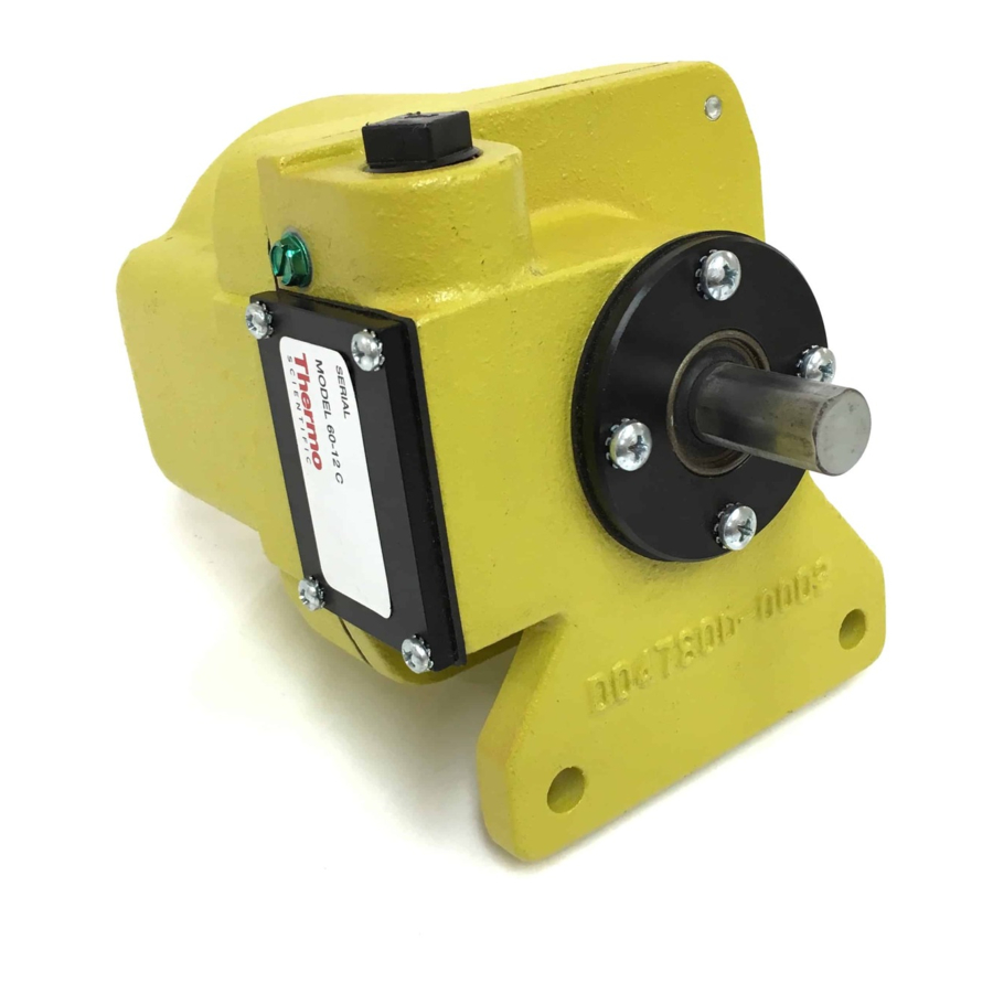
- Page 1 Speed Sensor Model 60-12 Operating and Service Manual REC 3016 Rev M Part number 005876—English...
- Page 2 Model 60-12 Speed Sensor This document is confidential and is the property of Thermo Fisher Scientific. It may not be copied or reproduced in any way without the express written consent of Thermo Fisher Scientific. This document also is an unpublished work of Thermo Fisher Scientific.
- Page 3 Revision History Revision A July 1985 Revision B February 1990 Revision C October 1990 Revision D September 1991 Revision E February 1992 Revision F June 1993 Revision G September 1995 Revision H May 1999 Revision J February 2001 Revision K April 2001 Revision L February 2003...
- Page 4 REC 3016 Rev M...
-
Page 5: Table Of Contents
Chapter 3 Operation ..................... 11 Overview ......................11 Model 60-12C ..................... 11 Model 60-12F ...................... 12 Model 60-12G ..................... 15 Model 60-12 ENC ....................15 Chapter 4 Maintenance ....................17 Overview ......................17 Calibration ......................17 Troubleshooting ....................17 Chapter 5 Service Repair and Replacement Parts ............ -
Page 6: List Of Figures
Wiring of 60-12 Speed Sensor Figure 3-1 Schematic Model 60-12C Speed Sensor Figure 3-2 60-12C Output Voltage Waveform Figure 3-3 60-12F, 60-12G, or 60-12 Enc Output Voltage Waveform Figure 3-4 Schematic, model 60-12F Speed Sensor Figure 3-5 Schematic, Model 60-12 ENC Figure 5-1... -
Page 7: About This Manual
Who Should Use this Manual? The Model 60-12 Speed Sensor Operating and Service Manual is a learning resource and reference for anyone concerned with installing, operating, or maintaining the Model 60-12 Speed Sensor. - Page 8 WARNING Failure to follow safe installation and servicing procedures could result in death or serious injury. Make sure only qualified personnel perform installation and maintenance procedures in accordance with the instructions in this manual. Allow only qualified electricians to open and work in the electronics cabinest, power supply cabinest, control cabinets, or switch boxes.
-
Page 9: Occupational Safety And Health Act (Osha)
WARNING Use only the procedures and new parts specifically referenced in this manual to ensure specification performance certification compliance. Unauthorized procedures or parts can render the instrument dangerous to life, limb, or property. CAUTION Do not place or store objects of any kind on the machine. -
Page 10: Thermo Fisher Scientific Warranty
Thermo Fisher Scientific Warranty The seller agrees, represents, and warrants that the equipment delivered hereunder shall be free from defects in material and workmanship. Such warranty shall not apply to accessories, parts, or material purchased by the seller unless they are manufactured pursuant to seller's design, but shall apply to the workmanship incorporated in the installation of such items in the complete equipment. -
Page 11: Disclaimer
Disclaimer Though the information provided herein is believed to be accurate, be advised that the information contained herein is not a guarantee for satis- factory results. Specifically, this information is neither a warranty nor guarantee, expressed or implied, regarding performance, merchantability, fitness, or any other matter with respect to the products, and recommendation for use of the product/process information in conflict with any patent. -
Page 13: Chapter 1 Introduction
Chapter 1 Introduction Overview The Thermo Scientific Model 60-12 Speed Sensor is designed and constructed for direct connection to a conveyor tail pulley, snugging roll, or large diameter return roller. The speed sensor employs a brushless pulse generator producing a stream of pulses, each pulse representing a unit of belt travel. -
Page 14: Unpacking And Inspection
RPM. The 60-12F is used for speeds from 3 to 30 RPM, and the 60-12G is used for speeds from 10 to 200 RPM. The 60-12 ENC Speed Sensor has a 500 pulse per revolution encoder inside, typically is used on slow RPM applications, and has a range of 0 to 200 RPM. -
Page 15: Chapter 2 Installation
4. Thread in supplied stub shaft coupling (part #037711) so that coupling collar bottoms out against tail pulley or snubbing shaft. See Figure 2-1. 5. Insert 60-12 speed sensor into coupling. Be sure to align shaft flat spot with set screws on coupling. Tighten all set screws securely. -
Page 16: Figure 2-1 Method A Installation
#002931 to couple 60-12 speed sensor to tail pulley shaft. (Refer to Figure 2-2.) This coupling is not supplied with the speed sensor but may be purchased separately from Thermo Fisher Scientific. -
Page 17: Restraint Arm Installation
Restraint Arm Installation 1. Attach restraint arm to speed sensor with two (supplied) 5/16” x 1-1/4” bolts. See Figure 2-3. The restraint arm should be mounted in a direction that will allow the sensor restraint arm to twist against the mechanical stop and in the direction of belt travel. - Page 18 Figure 2-3 Mounting Illustration Speed Sensor must not be mounted rigid. Use restraint arm and retaining spring. Mechanical stop and spring mount are by others. Attach spring in location such as to give 1/2” spring stretch. All wiring by others in accordance with system field wiring diagram and applicable codes.
- Page 19 Speed Minimum “A” Maximum “A” 100 FPM 2” 14” 200 FPM 4” 36” 300 FPM 6” 48” 400 FPM 8” 60” 500 FPM 10” 60” 600 FPM 12” 60” 700 FPM 14” 60” 800 FPM 16” 60” 900 FPM 18” 60”...
-
Page 20: Figure 2-4 Outline And Mounting Dimensions
Figure 2-4 Outline and Mounting Dimensions Notes: 1. Speed Sensor to be driven by conveyor tail pulley shaft or by special return roll. 2. Unit must be directly coupled to driving shaft. Do not drive with chains, belts, gears, etc. 3. -
Page 21: Electrical Wiring
Electrical Wiring Use the following procedures to make electrical connections: Remove the terminal strip cover (Figure 1-1) and the dust plug from the threaded conduit aperture in the speed sensor housing. Install 1/2 inch flexible conduit to the speed sensor housing. For 60-12C speed sensor, use Beldon 8760 or equivalent, 2 conductor, 18 AWG, shielded, when total length between speed sensor and totalizer is 200 feet or less. - Page 22 REC 3016 Rev M...
-
Page 23: Chapter 3 Operation
The pulse output signal is fed to the Integrator/Totalizer.. Model 60-12C The Model 60-12C supplies the output of the generator directly to the totalizer for high speed operation (20-200 RPM). Figure 3-1 Schematic Model 60-12 Speed Sensor Motor MFG Color Superior SS25 White Black Oriental 2CSM... -
Page 24: Model 60-12F
Figure 3-2 60-12C Output Voltage Model 60-12F Speed sensor Model 60-12F is designed for use in low speed systems (3 to 30 RPM). The 60-12F outputs 200 pulses per revolution, and requires and external power source of 15 to 30 VDC to operate. It contains a two-phase servo generator. The rotor is a 50-slot permanent magnet that is rotated in the stators. -
Page 25: Figure 3-3 60-12F, 60-12G, Or 60-12 Enc Output Voltage Waveform
Figure 3-3 60-12F, 60-12G, or 60-12 ENC Output Voltage Waveform REC 3016 Rev M... -
Page 26: Figure 3-4 Schematic, Model 60-12F Speed Sensor
Figure 3-4 Schematic, Model 60-12F Speed Sensor REC 3016 Rev M... -
Page 27: Model 60-12G
The Model 60-12 ENC (500) has a 500 pulse per revolution encoder with an internal pull up resistor. The output is approximately the voltage supplied at Terminal 17. See Figure 3-3. The 60-12 ENC requires an external power source of 5 to 24 VDC at 60 mA to operate. - Page 28 REC 3016 Rev M...
-
Page 29: Chapter 4 Maintenance
Chapter 4 Maintenance Overview When performing scale calibration, it is a good practice to inspect the shaft coupling for tightness. Also verify that the restraint arm is free to move. If arm has worn a slot in the restraint stop and the restraint bar cannot float back and forth as well as against the spring, corrections should be made. - Page 30 4.3.3 60-12 ENC Place a DC voltmeter across field terminals 17 (+) and 16 (-) of 60-12 ENC speed sensor. Depending on Model of scale integrator, reading should be 20, 24 or 30 VDC. If no voltage present, check at integrator terminals (see scale integrator manual).
-
Page 31: Service Repair And Replacement Parts
Model 60-12 Speed Sensor. It includes the telephone numbers for various departments at Thermo Fisher Scientific. The procedure for ordering replacement parts, a Return Material Authorization form on page 3, and the parts list for the 60-12 Speed Sensor is included in this chapter. -
Page 32: Parts Ordering Information
Parts Ordering Information For the fastest service when ordering parts, telephone or FAX the Thermo Fisher Scientific Parts Department at the numbers given below. Your regional field service representative can also assist you with parts orders, but this may delay shipment of your parts. -
Page 33: Contact Information
Contact Information Listed below is the contact information for Thermo Fisher Scientific offices worldwide. Australia +61 (0) 8 8208 8200 +61 (0) 8 8234 3772 fax Canada +1 (905) 888-8808 +1 (905) 888-8828 fax Chile +56 (0) 2 378 8050 +56 (0) 2 370 1082 fax China +86 (0) 21 6865 4588... - Page 34 United Kingdom +44 (0) 1788-820300 +44 (0) 1788-820301 fax United States +1 (800) 445-3503 +1 (763) 783-2525 fax +1 (763) 783-2500 direct REC 3016 Rev M...
-
Page 35: Return Material Authorization
Return Material Authorization 501 90 Avenue N.W. 1-800-445-3503 Minneapolis, MN 55433 Fax: 763.783.2525 12/9/2008 www.thermo.com Dear Customer, Thank you for using our in-house repair service. To expedite your repair, control costs, and ensure that safety requirements are met please follow these simple steps. Send in a copy of this completed form with a copy of your PO to the fax or email listed above. - Page 36 501 90 Avenue N.W. 1-800-445-3503 Minneapolis, MN 55433 Fax: 763.783.2525 12/9/2008 www.thermo.com PRODUCT INFORMATION: Part number: ______________________________ Part Description: ____________________________ Problem description: _____________________________________________________________________________ __________________________________________________________________________________ __________________________________________________________________________________ __________________________________________________________________________________ Part number: ______________________________ Part Description: ____________________________ Problem description: _____________________________________________________________________________ __________________________________________________________________________________ __________________________________________________________________________________ __________________________________________________________________________________ Part number: _____________________________ Part Description: ___________________________...
- Page 37 501 90 Avenue N.W. 1-800-445-3503 Minneapolis, MN 55433 Fax: 763.783.2525 12/9/2008 www.thermo.com DECONTAMINATION FORM Please complete all areas of the Decontamination Declaration below. • Orders without a Decontamination Declaration will not be processed and the instrument will be returned to the sender via collect freight.
-
Page 38: Parts List
001303 Capacitor, Tant 1-mf, 50-V 001173 60-12F Speed Sensor 002916 PCBA, Speed Sensor, 60-12F 002917 60-12G Speed Sensor 005905 60-12 ENC-500 Speed Sensor 045047 Encoder, 60-12 ENC-500 045050 Misc. Clamp Bar (Restraint Arm) 002920 Coupling, Stub Shaft, Speed Sensor 037711 Coupling Shaft, .625 Bore... -
Page 39: Figure 5-1 Centering Template For Speed Sensor
Figure 5-1 Centering Template for Speed Sensor REC 3016 Rev M... - Page 40 REC 3016 Rev M...
Need help?
Do you have a question about the 60-12 and is the answer not in the manual?
Questions and answers