Table of Contents
Advertisement
8
F
E
D
C
B
CTS 403 Flex Owner's
A
8
Manufactured Exclusively for
No part of this manual may be reproduced or used in any form or by any means (i.e. graphic, electronic, photocopying or electronic
retrieval systems) without the express written permission of Harris Research Inc. Specifications and information in this document
are subject to change without prior notice. All rights reserved. © 2020 Harris Research Inc.
7
6
Manual
7
6
HydraMaster
11015 47
Avenue West
th
Mukilteo, Washington 98275
MAN-47809 Rev. A, JAN 2020
(P/N 000-182-749)
5
4
5
4
3
U
D
BR
7
7
N
3
Advertisement
Table of Contents

Related Manuals for HydraMaster CTS 403 Flex


Summary of Contents for HydraMaster CTS 403 Flex
- Page 1 CTS 403 Flex Owner’s Manual Manufactured Exclusively for HydraMaster 11015 47 Avenue West Mukilteo, Washington 98275 MAN-47809 Rev. A, JAN 2020 (P/N 000-182-749) No part of this manual may be reproduced or used in any form or by any means (i.e. graphic, electronic, photocopying or electronic retrieval systems) without the express written permission of Harris Research Inc.
-
Page 3: Table Of Contents
High Altitude Operation .................. 1-13 Local Water Precautions ................. 1-13 OPERATING INSTRUCTIONS ..............S E C T I O N 2 Before Operating the CTS 403 Flex ..............2-1 Startup Procedure - Carpet/Upholstery ............2-2 Startup Procedure - Tile ..................2-4 Shut-Down Procedure .................. - Page 4 By-Pass Valve Assembly Parts List ..............8-39 Silencer Assembly Parts List ................8-40 Top Cover - CTS 403 Flex Assembly Parts List ..........8-41 Water Box Assembly Parts List ............... 8-43 70 Gallon Universal Recovery Tank (URT) Assembly Parts List ....8-46 Cover, 70 Gal URT, Single Vac Assembly Parts List ........
- Page 5 Chemical System .................... 10-1 Control Panel ....................10-1 Vacuum And Solution Hoses ................. 10-2 Cleaning Wand And Tool................. 10-2 Water Heating System ..................10-2 Hard Water Deposits ..................10-2 Flex System Warranty ..................10-4 v: CTS 403 Flex Owner’s Manual...
- Page 6 APPLICATION SCALE: 1:20 CODE: PRJ000245 WEIGHT: 810.39 The CTS 403 Flex is available with a 50 gallon tank assembly or a 35 gallon/15 gallon tank assembly. PROPRIETARY INFORMATION UNLESS OTHERWISE NOTED DIMENSIONS ARE IN INCHES 11015 47th Avenue West, BREAK ALL SHARP EDGES 0.005-.015...
-
Page 7: General Information
The truckmount portion of the CTS 403 Flex has been purposely modified to control the Flex System, ensuring that the two systems work seamlessly with each other. The truckmount system utilizes an internal combustion engine to provide the power necessary to turn both a blower (also referred to as a vacuum pump) and a high pressure water pump. -
Page 8: Contact Information
CONTACT INFORMATION If you have any questions regarding the operation, maintenance or repair of this machine, please contact your local distributor. When calling your distributor, be sure to reference the serial number and date of purchase. FOR YOUR REFERENCE: Serial No.______________________________________________ Date of Purchase:___________________ Purchased From (Distributor):_________________________________________ 1-3: General Information... -
Page 9: Warnings, Cautions And Notices
WARNINGS, CAUTIONS AND NOTICES The manufacturer uses this WARNING symbol throughout the guide to warn of possible injury or death. This CAUTION symbol is used to warn of possible equipment damage. This NOTICE symbol indicates that federal or state regulatory laws may apply, and also emphasizes supplemental information. - Page 10 Transporting a vented fuel container that presently contains, or has ever contained in the past, a flammable liquid is strictly forbidden by HydraMaster and by federal and state regulations. Doing so will increase the risk of fire and explosion. Serious injury or death may result.
- Page 11 Never smoke in or around the truckmount. Doing so will increase the risk of fire and explosion. Serious injury or death may result. Be cautious when drilling holes through the van floor. Many vans have critical components mounted directly below the van floor that could be damaged by a misplaced drill bit.
- Page 12 Never operate the truckmount with a water hardness reading measuring 3.0 grains per gallon or higher. Using reading than 3.0 grains per gallon will cause scale to build up inside the truckmount water system. Scale build up causes serious component damage. Test all water prior to use and use water softening equipment if necessary.
-
Page 13: Responsibilities
RESPONSIBILITIES The Purchaser’s Responsibilities Prior to purchasing a van, ensure that the payload is suitable for all of the equipment that will be installed and transported. This includes and is not limited to: the truckmount, recovery tanks, fresh water tanks and on-board water, hose reels, hoses, cleaning tools, chemicals, drying equipment, etc. - Page 14 • Ensure proper connection of the fuel lines. • Ensure proper connection and installation of the battery. Verify that the battery is in accordance with HydraMaster’s recommendation. • Check the pump, vacuum blower and engine oil levels prior to starting the truckmount.
-
Page 15: Machine Specifications - Console
MACHINE SPECIFICATIONS - CONSOLE Frame Dimensions 24.0" W x 31” H x 36" D Weight 568 lbs Engine- Briggs and Oil Type Synthetic 5W-30 Stratton Vanguard 23HP Capacity Approx. 1 1/2 quarts (48 oz.) when changing oil and filter Engine rpm 3,150 rpm Fuel Consumption 1.1 gph... - Page 16 Standard Equipment High Pressure Hose 1/4" High Temperature Lined/ Vinyl Cover - 100 ft. Vacuum Hose 2" Vacuum Hose- 100 ft. 1-1/2" Wand Whip Line- 10 ft. Recovery Tank 70 gallon MaxAir Universal Tank Through Floor Exhaust Kit Battery Box Van Decal Van Installation Kit Owner’s Manual (on CD)
-
Page 17: Machine Specifications - Flex Assemblies
MACHINE SPECIFICATIONS - FLEX ASSEMBLIES 50 Gallon Tank Dimensions 12” W x 33” H x 60” L with Frame Weight 113 lbs 35/15 Gallon Dimensions 12” W x 33” H x 53” L Tanks with Frame Weight 108 lbs Construction Frames Steel Tanks... -
Page 18: High Altitude Operation
Hard Water Advisory HydraMaster recognizes that any hard water deposits which might occur within the water system of our truckmounts is a serious problem. The precision technology of truckmount heat exchanger systems is intolerant of any foreign material. Hard water deposits will ultimately decrease the performance of the system and are expected to seriously lower the reliability of the machine. - Page 19 Hard Water Area Map The hard water map, shown in Figure 1-1, defines hard water areas in the continental United States which compromise fluid related components such as hoses, fittings, heaters, pumps, valves and water-cooled engines. For other countries, hard water area maps can be obtained from geological societies.
- Page 20 Cleaning efficiency and equipment life is increased, chemical use decreased, and the appearance of cleaned carpets enhanced when water softeners are incorporated in hard water areas. HydraMaster strongly urges the use of water softener units with the CTS 403 Flex in areas exceeding 3.0 grains per gallon.
- Page 21 Another solution to the disposal problem is to equip your CTS 403 Flex with an Automatic Pump Out (APO). These systems are designed to remove waste water from the extractor’s recovery system and actively pump the water through hoses to a suitable disposal drain.
-
Page 22: Operating Instructions
Owner’s Manual. Locate the van and equipment in a well-ventilated area. The CTS 403 Flex generates toxic fumes. Position the vehicle so that the fumes will be directed away from the job site. Do not park where exhaust fumes can enter a building through open doors, windows, air conditioning units or kitchen fans. -
Page 23: Startup Procedure - Carpet/Upholstery
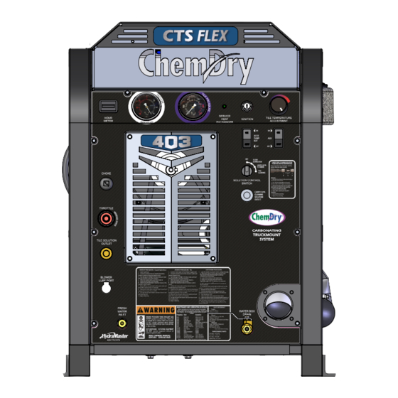
Temperature Control Vacuum Gauge Hour Meter Choke AUX Switch Throttle APO Switch Solution Tile Control Switch Solution Outlet Carpet/Uph. Cleaning Blower Lube Solution Port Outlet Incoming Fresh Water Box Water Drain Figure 2-1. CTS 403 Flex Dash Assembly Operating Instructions: 2-2... - Page 24 Mukilteo, Washington 98275 MACHINE TOLERANCES FINISH .X= .1 .XX= .03 .XXX= .010 ANGULAR = 2° ASSEMBLY, DASH - CTS 403 FLEX - - - - - - - - - - - - - - - - - - SIZE...
-
Page 25: Startup Procedure - Tile
Mukilteo, Washington 98275 MACHINE TOLERANCES FINISH .X= .1 .XX= .03 .XXX= .010 ANGULAR = 2° ASSEMBLY, DASH - CTS 403 FLEX - - - - - - - - - - - - - - - - - - SIZE... - Page 26 Pressure Regulator Figure 2-4. Side View of CTS 403 Flex Console 10. Block off the vacuum inlet to the waste tank and allow TM to warm up for 2-3 minutes. Un-cap vacuum and attach vacuum hose to unit and cleaning tool.
-
Page 27: Shut-Down Procedure
SHUT-DOWN PROCEDURE Lube the blower to prevent it from rusting internally. Allow the unit to run for a few minutes with the vacuum hose disconnected in order to remove moisture from the blower. Cap off the inlet to the vacuum tank. Spray a LPS TKX spray lubricant into the “BLOWER LUBE PORT”... -
Page 28: Flex Tank Operation
FLEX TANK OPERATION Make sure the 3-way ball valve levers are all in the downward or vertical position (see Figure 2-5). The levers on the Flex pumps control the direction of the chemical flow. When the levers are in the vertical position, the flow is turned “OFF”. LEVER 3-WAY BALL VALVES... - Page 29 There are 2 levers on the 35 Gallon/15 Gallon Tank Assembly, one for each tank (see Figure 2-5). There is 1 lever located on the 3-way ball valve on the 50 Gallon Tank Assembly (see Figure 2-6). Before operating the Flex System, turn the appropriate lever toward the direction of the flow (toward the hose connected to the pump strainer - see Figure 2-6 and Figure 2-7).
-
Page 30: Freeze Guarding
3 - Freeze Guarding When operating the CTS 403 Flex during the colder months of the year, ensure that you properly freeze guard the System. No part of the CTS 403 Flex is covered by warranty if machine damage occurs because of freezing. -
Page 31: Freeze Guarding The Carpet/Upholstery System
FREEZE GUARDING THE CARPET/UPHOLSTERY SYSTEM Connect a solution line to Carpet/Uph. Cleaning Solution Outlet with the tool of your choice attached at the end. Place the tool into a container to collect the solution from the tool. Pour 2 gallons of 50/50 antifreeze and water into each Flex tank. Turn the ignition switch to the “ON”... -
Page 32: Freeze Guarding The Tile System
FREEZE GUARDING THE TILE SYSTEM With the truckmount turned off and the incoming water line disconnected, open the water box drain valve on the front of the truckmount. Allow the system to fully drain. Add 2 gallons of 50/50 antifreeze and water mix to the water box. Attach a section of solution hose to the outgoing solution fitting on the front of the machine. - Page 33 Freeze Protection of the Pump-In System Drain the fresh water tank. Remove the garden hose adapter from the pump-in pump hose and position the hose so it is pointing outside the van. Turn on the pump-in pump and run for 1-2 minutes until all the water is purged from the hose.
-
Page 34: Machine Maintenance
Owner’s Guide. Records of maintenance must be kept and copies may be required to be furnished to HydraMaster before the warranty is honored. It is recommended that you affix a copy of the log on the vehicle door near your unit for convenience and to serve as a maintenance reminder. -
Page 35: Operational Maintenance
• Inspect the truckmount for water and oil leaks, loose electrical connections, etc. and repair as needed. • Lubricate the blower lube port with HydraMaster-recommended spray lubricant. Weekly Maintenance • Inspect the recovery tank filters for tears, holes, etc. Repair or replace as needed. - Page 36 250 Hours • Check coupler (rubber sleeve) for cracks or wear. Replace as necessary. 500 Hours • Change the blower oil. • Change the high pressure pump oil. • Check the engine valve clearance (intake and exhaust 0.004” - 0.006”) •...
-
Page 37: High Pressure Pump Maintenance
HIGH PRESSURE PUMP MAINTENANCE Daily Check the oil level and the condition of the oil. The oil level should be up to the center of the sight glass on the rear of the pump or between the “MIN” and “MAX” lines on the dipstick. - Page 38 Valve Maintenance (See Figure 4-1) Using a 22-mm wrench or socket, remove all six valve caps on the manifold of the pump. Examine each valve cap O-ring for cuts or distortions and replace if worn. Using needle nose pliers, remove the suction and delivery check valves. The valve assembly usually stays together when removing.
- Page 39 Replace old valves with new valves by placing the assembly in the valve chamber. Press down firmly on the top of the valve assembly. Replace valve caps by applying LOCTITE® 243 to valve cap and torque to 33 ft- lbs. Removing and Replacing Pump Manifold Remove the manifold of the pump by taking a 5-mm Allen head wrench and removing the eight head bolts.
- Page 40 Torque to 4.5 ft-lbs. Servicing the Crankcase While the manifold and plungers are removed, rotate the crankshaft by hand. Closely examine the crankcase oil seals for drying, cracking or leaking. Consult the local HydraMaster distributor if crankcase servicing is necessary. 4-7: Machine Maintenance...
-
Page 41: Vacuum System Maintenance
VACUUM SYSTEM MAINTENANCE The vacuum pump in this machine is commonly referred to as a “rotary positive displacement blower” or “blower” for short. The performance and life of the truckmount is greatly dependent on the care and proper maintenance it receives. Review the blower’s owner’s manual, which has been included, for a better understanding of this piece of machinery. - Page 42 Daily At the end of each day the internal components of the blower need to be lubricated. This helps to prevent rust deposits and prolongs the life of the truckmount. Lubricate the blower to prevent it from rusting internally by: Allow the unit to run for a few minutes with the vacuum hose disconnected in order to remove moisture from the blower.
-
Page 43: Descaling Procedure -Tile
DESCALING PROCEDURE -TILE Scale deposits on the interior of the heating system can cause a noticeable loss in heating performance. Deposits of this kind result from hard water deposits. The frequency with which descaling procedures are required will vary. If the area has particularly hard water, you may have to descale often. -
Page 44: Descaling Procedure- Carpet/Upholstery
DESCALING PROCEDURE - CARPET/UPHOLSTERY Connect a solution hose to the Carpet/Uph. Cleaning Solution Outlet. Route the other end of the solution hose to the Flex tank. Attach an open quick connect to the other end of the hose. The descaler will drain from the female QC fitting assembly/hose quickly. Have extra buckets ready to swap out because each bucket should fill quickly. -
Page 45: Tensioning The Pump Drive Belt
TENSIONING THE PUMP DRIVE BELT Remove the CTS 403 Flex grill to gain access to the idler pulley. Loosen but do not remove the 2 ½” long bolt (P/N 000-143-716) on the idler pulley. See Section Owner’s Manual. Remove the right cover of the machine to gain access to the tensioning screw. -
Page 46: Pump Tuning Instructions
PUMP TUNING INSTRUCTIONS Pump tuning for the CTS 403 Flex allows the pump pressure switch to turn off when there is no flow out of the tool. This reduces the pump operating temperatures and increases the pump durability. Pump tuning should be performed every 60 days. - Page 47 Start-up Pump Tuning Procedure Connect the tool’s solution hose to the quick disconnect. Turn the ignition switch to the “ON” position. You do not need to start the unit since vacuum is not needed for this procedure. Select “CARPET/UPH.” on the Solution Control switch. With the pump still on, disconnect the solution hose from the Flex unit.
- Page 48 Adjustment If the pump continues to run for longer than 3 to 5 seconds, turn the screw counterclockwise until the pump switches off (see Figure 4-5). If the pump switches off as soon as the hose is disconnected (less than 3 to 5 seconds), turn the pump screw clockwise one complete turn.
-
Page 49: Clean Qc Filter And Orifice
CLEAN QC FILTER AND ORIFICE Clean and inspect the in-line quick connect filter and orifice every 100 hours. Remove the quick connect assembly on the Carpet/Uph. Cleaning Solution Outlet (see Figure 4-6). Hold the hex closest to the panel using a 11/16” open end wrench and turn the hex assembly for the quick connect with a 13/16”... -
Page 50: Service Heat Exchanger Indicator - Cts 403
SERVICE HEAT EXCHANGER INDICATOR - CTS 403 The engine backpressure is measured at a small port on the inlet plenum of the heat exchanger assembly. The exhaust of the blower and engine combine at the plenum and represents the most accurate pressure reading for the engine exhaust. It is the combination of these two systems that is being monitored by the pressure switch, located on the right-hand side of the machine with the other relays and fuses. -
Page 51: Cleaning Out The Heat Exchanger Of The Cts 403
CLEANING OUT THE HEAT EXCHANGER OF THE CTS 403 During routine maintenance, and when the SERVICE HEAT EXCHANGER light is a continuous red during operation, access to the heat exchanger assembly can be made by removing the cover plates of the plenum. With the unit off, use a 5/16” nut driver or socket to remove the left side panel of the inlet plenum. -
Page 52: Solution Flow Paths
5 - Solution Flow Paths This section shows the high and low pressure flow diagrams. 5-1: Solution Flow Paths... - Page 53 HIGH TEMP FINNED TUBE SHUTDOWN THERMOSTAT HEAT EXCHANGER SW-4 TS-1 PROPRIETARY INFORMATION 11015 47th Avenue West, Mukilteo, Washington 98275 BLOWER AND ENGINE FLOW DIAGRAM - CTS 403 FLEX EXHAUST IN DATE SIZE PART NUMBER DRAWN M.B.B. 1/10/2020 000-179-856 CHECKED C.I.R.
- Page 54 BLOWER EXHAUST BLOWER EXHAUST STAINLESS STEEL COPPER APO OUT HEAT EXCHANGER HEAT EXCHANGER CHECK VALVE DIVERTER VALVE EXHAUST OUT VACUUM BLOWER SILENCER Solution Flow Path: 5-4 PROPRIETARY INFORMA 11015 47th Avenue W Mukilteo, Washington 9 FLOW DIAGRAM - CTS 403 FLEX...
-
Page 55: Electrical System
„ Electrical Schematic „ Wiring Diagram The CTS 403 Flex electrical system operates on 12 V DC which is provided by the battery. Battery levels are maintained by a 20 Amp alternator that is built into the engine. When a new battery is installed, check that it is properly charged before installation or damage to the charging system may occur. - Page 56 SW-5 FUSE FLOOD NATURAL DAMAGE SYSTEM SYSTEM FU-1 PROPRIETARY INFORMATION 11015 47th Avenue West, Mukilteo, Washington 98275 ELECTRICAL SCHEMATIC - CTS 403 FLEX NOTES: 6-3: Electrical System DATE SIZE PART NUMBER REFERENCE DRAWINGS DRAWN M.B.B. WIRING DIAGRAM________________________000-179-854 01/13/2020 000-179-855 FLOW DIAGRAM__________________________000-179-856 C.I.R.
- Page 57 [TO NATURAL PUMP PMP-4 #P-16] 50(BLK) - 14 GA *ALL WIRES ARE 18 GAUGE UNLESS OTHERWISE STATED [TO TEMPERATURE CONTROLLER - TC-1 #TR1] 51(ORG/WHT) Electrical System: 6-4 PROPRIETARY INFORMATION 11015 47th Avenue West, Mukilteo, Washington 98275 WIRING DIAGRAM - CTS 403 FLEX...
- Page 58 GREEN - DENOTES COMPONENTS AUTOMATIC PUMP OUT PROPRIETARY INFORMATION *ALL WIRES ARE 18 GAUGE UNLESS OTHERWISE STATED (OPTIONAL) 11015 47th Avenue West, Mukilteo, Washington 98275 6-5: Electrical System WIRING DIAGRAM - CTS 403 FLEX DATE SIZE PART NUMBER DRAWN M.B.B. 12/23/2019...
-
Page 59: Troubleshooting
7 - Troubleshooting This section describes the standard troubleshooting procedures in the following areas: „ Heating System „ Engine „ Tile System „ Carpet/UPH System „ Vacuum System 7-1: Troubleshooting... -
Page 60: Heating System
HEATING SYSTEM 1.0 Truckmount overheats and shuts down Possible Cause Solution 1.1 The tile orifice or filter Remove and inspect. Clean as necessary. screen are restricted. 1.2 The tile dump solenoid is Inspect the solenoid and the hose that delivers restricted. -
Page 61: Engine
ENGINE 1.0 Will not turn over Possible Cause Solution 1.1 A loose or corroded Clean and tighten the battery terminal connections. battery terminal. 1.2 The battery is dead. Recharge or replace the battery. Test the charging system. Repair if necessary. Do not attempt to jump start the truckmount from a running vehicle. - Page 62 3.0 Turns over but will not start; there is spark. (To check for spark, refer to engine manual.) Possible Cause Solution 3.1 Fuel is not reaching the Test for power to the fuel pump. Refer to Electrical carburetor. Section. If power is present, inspect the fuel pump. Replace if necessary.
- Page 63 5.0 Runs rough at high speed Possible Cause Solution 5.1 The spark plug(s) are Remove and inspect the plugs. Clean or replace as faulty. necessary. 5.2 The spark plug wire(s) are Inspect the wires and connectors for damage or faulty. loose connections.
- Page 64 7.0 Engine overheats Possible Cause Solution 7.1 Poor ventilation in the van. Open all the van doors. Install a roof vent in the van. Remove any dividers or other objects impeding airflow around the truckmount. 7.2 Low oil level. Check the level and fill as necessary. Running the engine with a low oil level can cause severe damage to the engine.
-
Page 65: Tile System
TILE SYSTEM 1.0 The pump will not come up to normal cleaning pressure Possible Cause Solution 1.1 The tile pressure adjusting Inspect the valve. Repair or replace if necessary. valve is faulty. 1.2 Worn seals or valves in Test the pump output volume directly from the pump the tile pump. - Page 66 3.0 The psi gauge reads normal; low pressure from wand Possible Cause Solution 3.1 Restriction in the cleaning Inspect the tool jet(s) and clean or replace as tool. necessary. Inspect any filters in the cleaning tool and clean or replace as necessary. 3.2 Faulty quick connect in the Inspect each quick connect and replace as system.
- Page 67 5.0 Water box empty or fills slowly Possible Cause Solution 5.1 Restriction in the water Inspect the supply system from the source through supply system. the incoming quick connect. 5.2 The float valve in the Disassemble and inspect the valve. Repair or water box is faulty.
- Page 68 CARPET/UPHOLSTERY SYSTEM 1.0 Unit does not spray soulution in carpet/uphostry mode Possible Cause Solution 1.1 Solution tank(s) are empty. Fill as necessary. 1.2 Hose is not fully Make sure hose quick connects are all fully engaged connected. and attached to machine. 1.3 Solution hose valve is Check hoses from the dash to the carpet/uphostry shut-off...
-
Page 69: Vacuum System
VACUUM SYSTEM 1.0 A weak vacuum at wand. The gauge reads normal. Possible Cause Solution 1.1 Blockage in the hoses or Disconnect the hoses and check for an obstruction. wand tube 1.2 Excessive length of Do not attach excessive lengths of hose. hose connected to the truckmount 2.0 A weak vacuum... - Page 70 5.0 The vacuum blower is locked and will not turn Possible Cause Solution 5.1 Truckmount has been Spray penetrating oil into the blower and let sit for inactive for a period of at least 1 hour. Then very carefully use pipe wrench time and the blower was on the outer diameter of the pulley on the coupler not properly lubricated...
- Page 71 7-13: Troubleshooting...
-
Page 72: Assemblies And Parts List
„ Silencer Assembly Parts List ................8-40 „ Machine Assembly with 50 Gallon Tank Parts List ..........8-6 „ Top Cover - CTS 403 Flex Assembly Parts List ..........8-41 „ Console Assembly Parts List ................8-13 „ Water Box Assembly Parts List ................8-43 „... - Page 73 HydraMaster equipment. Refer to Figure 8-1 to identify those substances such as A1, A2 and so forth. Equivalent products are acceptable if they meet or exceed current specifications and are approved by HydraMaster. Figure 8-1. Adhesive/Sealant Material Reference...
- Page 74 Figure 8-2. Machine Assembly with 35 Gallon Tank and 15 Gallon Tank - View 1 of 2 000-068-776 750-010-758-10 Rev. C HOSE, 2.5" ID X 30" LG. (PART OF 000-078-614) 000-078-957 DUMP HOSE HOOK UP KIT OPTIONAL INSTALL: DUMP HOSE HOOK UP KIT (PART OF 000-078-614) (PART OF 000-078-614) ITEM NO.
-
Page 75: Machine Assembly With 35 Gallon Tank And 15 Gallon Tank Parts List
Machine Assembly with 35 Gallon Tank and 15 Gallon Tank Parts List 41.630 Item Part Number Description 33.451 610-050-749 ASSEMBLY, CONSOLE - CTS 403 FLEX 000-163-751 ASSEMBLY, TANK - 35/15 GAL - HRI FLEX KIT 610-003-749 ASSEMBLY, 70 GALLON URT - CTS 403 000-041-707... - Page 76 000-068-776 HOSE 2.5" ID X 30" LG. Figure 8-4. Machine Assembly with 50 Gallon Tank - View 1 of 2 (PART OF 000-078-614) 750-010-749-10 Rev. B KIT, T KIT, P KIT, IN HOSE HOSE 000-078-957 HOSE DUMP HOSE HOOK UP KIT OPTIONAL INSTALL: DUMP HOSE HOSE (PART OF 000-078-614)
-
Page 77: Machine Assembly With 50 Gallon Tank Parts List
750-010-749-10 Rev. B Machine Assembly with 50 Gallon Tank Parts List Item Part Number Description 610-050-749 ASSEMBLY, CONSOLE - CTS 403 FLEX 000-163-751 ASSEMBLY, TANK - 50 GAL - HRI FLEX KIT 610-003-749 ASSEMBLY, 70 GALLON URT - CTS 403... - Page 78 Figure 8-6. Console Assembly - View 1 of 6 610-050-749 Rev. C 8-7: Assemblies and Parts Lists...
- Page 79 Figure 8-7. Console Assembly - View 2 of 6 610-050-749 Rev. C Assemblies and Parts Lists: 8-8...
- Page 80 Figure 8-8. Console Assembly - View 3 of 6 610-050-749 Rev. C 8-9: Assemblies and Parts Lists...
- Page 81 Figure 8-9. Console Assembly - View 4 of 6 610-050-749 Rev. C Assemblies and Parts Lists: 8-10...
- Page 82 Figure 8-10. Console Assembly - View 5 of 6 610-050-749 Rev. C DRAWN L.O.L. CHECKED M.B.B. APPVD M.B.B. SCALE: 1:4 8-11: Assemblies and Parts Lists...
- Page 83 4.188 35.125 Figure 8-11. Console Assembly - View 6 of 6 610-050-749 Rev. C 24.000 33.451 30.940 28.000 Assemblies and Parts Lists: 8-12...
-
Page 84: Console Assembly Parts List
HOSE, 1/2” I.D. RUBBER x 56” LG. (PUMP TO WB) 610-001-749 ASSEMBLY, FRAME - CTS 403 FLEX 000-068-969 HOSE, 1/2” I.D. RUBBER x 69” LG. (FRESH WATER IN TO 610-005-749 ASSEMBLY, HEAT EXCHANGER - CTS 403 FLEX 610-021-729 ASSEMBLY, ORIFICE 000-068-997 “HOSE, 1/4”” I.D. RUBBER X 60”” LG. 610-007-747 ASSEMBLY, PUMP - CTS 403 FLEX (POP OFF VALVE TO THERMO VALVE TEE) &... - Page 85 Figure 8-12. Blower Assembly - View 1 of 2 610-002-747 Rev. B See Figure 8-1 for adhesive/sealant information. REVISIONS DESCRIPTION CODE DATE CHKD APPVD RELEASED DRAWING. ECR #2773 06/16/2017 P.E. C.I.R. ECRB ADD TIE WRAP TO SECURE BOTH ENDS TOGETHER CRIMP HOSE CLAMPS 000-027-112 SO THAT HOSES WILL...
-
Page 86: Blower Assembly Parts List
- - - - - - - - - DRAWN P.E. 6/14 - - - - - - CHECKED C.I.R. 6/14 610-050-749 CTS 403 FLEX NEXT ASSY USED ON APPVD ECRB 6/14 APPLICATION SCALE: 1:4 8-15: Assemblies and Parts Lists... - Page 87 Figure 8-14. Dash Assembly - View 1 of 2 610-018-749 Rev. B 000-081-410 LABEL, THERMOSTAT All labels part of label set P/N 000-081-555. Individual labels not available for purchase. 000-081-556 LABEL, DASH Assemblies and Parts Lists: 8-16...
- Page 88 METER, RECTANGULAR HOUR w/o BEZEL VARIOUS LIGHT, RED LED INDICATOR MINI VARIOUS LABEL, DOME - 403 POLYESTER LABEL SET - CTS 403 FLEX POLYCARBONATE INSERT, #F23 (1/8" FPT x 3/16" BARB) BRASS INSERT, #68 (3/8" NPT x 1/2" BARB) BRASS INSERT, #66 (3/8"...
-
Page 89: Dash Assembly Parts List
000-052-189 TEE, 1/4” FEMALE SS 000-052-096 INSERT, #F23 (1/8” FPT x 3/16” BARB) 000-149-025 THERMOSTAT, BULB & CAPILLARY 000-081-555 LABEL SET - CTS 403 FLEX 000-131-131 TRIMLOK, 3/8” x 1/8” RUBBER 3.33’ 000-131-131 LABEL, DOME - 403 000-169-064 VALVE, 3/8” NPT FULL PORT BALL... - Page 90 HIDDEN FROM VIEW UNDER CARBURETOR. TORQUE TO 25 FT LBS 000-049-258 FILTER, B&S FUEL Figure 8-16. Engine Assembly - Part 1 of 2 610-004-749 Rev. A HIDDEN FROM VIEW UNDER CARBURETOR. TORQUE TO 25 FT LBS 000-049-258 FILTER, B&S FUEL DETAIL A NOTES: SCALE 1 : 2...
- Page 91 REVISION DESCRIPTION RELEASE DRAWING. Figure 8-17. Engine Assembly - Part 2 of 2 610-004-749 Rev. A 000-049-053 FILTER, B&S VANGUARD FOAM AIR FILTER 000-049-012 FILTER, 16HP AIR-VANGUARD I/C 000-106-009 PLUG,1/8" NPT ALLEN HEAD WASHER, 5/16" FLAT, USS WASHER, 1/4" FLAT WASHER, #10 FLAT VALVE, CHECK - DIVERTER CONTROL 3.33' TRIMLOK, 3/4"...
-
Page 92: Engine Assembly Parts List
Engine Assembly Parts List Item Part Number Description Item Part Number Description 000-094-012 NUT, 5/16”-18UNC HEX 000-020-025 BUSHING, H X 1” 000-094-125 NUT, 6MM HEX NYLOCK FLANGE S/S 000-033-117 CLAMP, 1” CUSHION LOOP w/ 7/16 MOUNT HOLE 000-105-562 PLATE, ENGINE DUCT - COATED 000-039-060 COUPLER, GUARDIAN 7/8”... -
Page 93: Exhaust Assembly Parts List
ASSEMBLY, DIVERTER VALVE ACTUATOR ASSEMBLY, EXHAUST MANIFOLD - CTS 403 VARIOUS 610-013-009 ATTACH THESE TWO SUB-ASSEMBLIES 610-013-007 ASSEMBLY, EXHAUST DIVERTED - CTS 403 FLEX BEFORE INSTALLATION ON MACHINE ASSEMBLY, EXHAUST DIVERTER VALVE - CTS 403 VARIOUS 610-013-010 610-013-010 ASSEMBLY, EXHAUST DIVERTER VALVE - CTS 403... -
Page 94: Diverter Valve Actuator Assembly Parts List
Figure 8-19. Diverter Valve Actuator Assembly 610-014-728 Rev. F Diverter Valve Actuator Assembly Parts List See Figure 8-1 for sealant information. Item Part Number Description 000-015-016 Bracket Actuator - Coated 000-015-750 Bracket, Air Cylinder Mount - Inner Coated 000-015-748 Bracket, Air Cylinder Mount - Outer - Coated 000-052-106 Insert, 1/8”... - Page 95 REVISION DESCRIPTION CODE DATE CHKD APPVD ADDED ITEM 6. BETA 1/6/2016 L.O.L. C.I.R. C.I.R. REPLACED 4 QTY. 000-143-141 WITH 000-143-758. REMOVED 4 QTY. 000-174-069, ADDED 2 QTY. 000- 02/01/2019 R.D.D. ECR #2835 174-208 AND 000-174-209. UPDATED THE HEAT SHEILD INSTALLATION NOTE. Figure 8-20.
-
Page 96: Exhaust Diverted Assembly Parts List
Exhaust Diverted Assembly Parts List Item Part Number Description Item Part Number Description 000-143-124 SCREW, 5/16”-18UNC x 1.75” LG. HEX HEAD 000-033-068 CLAMP, 1-1/2” EXHAUST 000-143-572 SCREW, 5/16”-18UNC x 5/8” LG. GRD. 5 HEX HEAD 000-041-043 COVER, DIVERTER EXHAUST 000-125-199 TUBE, EXHAUST DIVERT - WELDMENT 000-105-181 FLANGE, Ø1.50”... -
Page 97: Exhaust Diverter Valve Assembly Parts List
- - - DRAWN L.O.L. 01/21/2020 SIZE PART NUMBER LINE REFERNCE CARD FOR SEALANT INFORMATION. 610-013-749 CTS 403 FLEX CHECKED M.B.B. 01/21/2020 2. DO NOT BEND TAB WASHERS UNTIL AFTER THE 610-013-010 000-155-030 SPRING, LEAF - WELDMENT FASTENERS ON THE ASSEMBLY HAVE BEEN TORQUED. -
Page 98: Exhaust Manifold Assembly Parts List
REVISION DESCRIPTION CODE DATE CHKD APPVD RELEASE DRAWING. 01/21/2020 L.O.L. M.B.B. M.B.B. Figure 8-22. Exhaust Manifold Assembly ALANT E2 610-013-008 Rev. B s.in REVISION DESC RELEASE DRAWING. SEALANT E2 2X Torque Spec: 12.0 lbs.ft or 144 lbs.in e Spec: 16.5 lbs.ft or 200 lbs.in 20MM GR. - Page 99 ADDED 033-128; 143-583 WAS QTY. 8; MOVED 2 01/14/2020 L.O.L. M.B.B. M.B.B. CLAMPS. 000-081-327 LABEL, ANSI WARNING Figure 8-23. Frame Assembly - View 1 of 2 TEXT ONLY 610-001-749 Rev. B See Figure 8-1 for adhesive/sealant information. 000-081-558 CLEAN FILTERS &...
- Page 100 Figure 8-24. Frame Assembly - View 2 of 2 610-001-749 Rev. B 000-081-327 LABEL, ANSI WARNING TEXT ONLY 000-081-461 LABEL, TILE/STONE REGULATOR INSTALL PRIOR TO ROUTING HOSES 8-29: Assemblies and Parts Lists...
-
Page 101: Frame Assembly Parts List
ASSEMBLY, BACK PRESSURE SWITCH MOUNT 000-033-067 CLAMP, 2” CUSHION LOOP 610-021-009 ASSEMBLY, IDLER PULLEY 000-033-134 CLAMP, 3/4 ID, CUSHION 610-026-747 ASSEMBLY, SOLENOID VALVE - CTS 403 FLEX 000-033-128 CLAMP, 3/8” NYLON HOSE 000-015-1304 BRACKET, HOSE TIE DOWN 000-055-195 FRAME, COMPLETE - COATED 000-027-110 CAP, 2”... -
Page 102: Idler Pulley Assembly Parts List
3 QTY. 000-174-012 WAS 1 AND ADDED NOTE 1. REPLACED 000-154-128 WITH 000-154-049. ADDED REPLACED 000-154-128 WITH 000-154-049. ADDED ECR #2635 ECR #2635 3/3/2016 3/3/2016 C.I.R. C.I.R. ECRB ECRB 3 QTY. 000-174-012 WAS 1 AND ADDED NOTE 1. 3 QTY. 000-174-012 WAS 1 AND ADDED NOTE 1. Figure 8-25. -
Page 103: Solenoid Valve Assembly Parts List
Figure 8-26. Solenoid Valve Assembly 610-026-747 Rev. B Solenoid Valve Assembly Parts List Item Part Number Description Item Part Number Description 000-015-1295 Bracket, Temp Control - Coated 000-143-012 Screw, 5/16”-18UNC X 3/4” Lg. 000-074-125 Controller, Temp Single Analog Input - RTD 000-169-226 Solenoid, Air Actuator 4- Way Valve 000-052-293... -
Page 104: Back Pressure Switch Mount - Cts 403 Assembly Parts List
- - - SIZE - - - - - - DRAWN L.O.L. 12/19/2019 PART NU 610-02 610-001-749 CHECKED M.B.B. 12/19/2019 CTS 403 FLEX NEXT ASSY USED ON APPVD M.B.B. 12/19/2019 APPLICATION SCALE: 1:1 CODE: PRJ000242 WEIGHT: 1.03 Back Pressure Switch Mount - CTS 403 Assembly Parts List WASHER, 5/16"... - Page 105 Figure 8-28. Heat Exchanger Assembly 610-005-749 Rev. G PART OF 000-149-025 See Figure 8-1 for adhesive/sealant information. Assemblies and Parts Lists: 8-34 ITEM NO. UNLESS OTHE DIMENSIONS BREAK ALL SHAR TOLERANCE .X= .1 .XX= .03 .XXX= .01...
-
Page 106: Heat Exchanger Assembly Parts List
Heat Exchanger Assembly Parts List Item Part Number Description Item Part Number Description 000-052-738 ADAPTER, 1/4” NPT x 1/2” FPT 000-149-566 SENSOR, 6” - 90° RTD 000-013-136 BOX, OUTLET PLENUM - WELDED - CTS 403 000-052-190 TEE, 1/4” BRANCH SS 000-013-135 BOX, PLENUM CTS 403 - WELDMENT 000-052-023... -
Page 107: Orifice Assembly Parts List
Figure 8-29. Orifice Assembly 610-021-729 Orifice Assembly Parts List Item Part Number Description 000-052-084 Elbow, 1/8” NPT Street 000-049-052 Filter Cartridge,1/4” Brass 000-052-153 Housing, Stabilizer Nozzle 000-052-530 Nipple, 1/4” SAE X 1/8” NPT 000-052-586 Nipple, 1/8” FPT X 1/4” SAE 000-052-582 Nipple, Tee Jet Style Collar X 1/8”... - Page 108 Figure 8-30. Pump Assembly 610-007-747 Rev. B See Figure 8-1 for adhesive/sealant information. 8-37: Assemblies and Parts Lists...
-
Page 109: Pump Assembly Parts List
Pump Assembly Parts List Item Part Number Description Item Part Number Description 610-009-747 Assembly, By-Pass Valve - CTS 403 Flex 000-094-038 Nut, 5/16”-18UNC Hex Nylock 000-036-008 Clutch, 7” O.D. 24MM Single Groove 000-105-148 Plate, Clutch Mount Pump 000-052-087 Elbow, 1/2” NPT Street... -
Page 110: By-Pass Valve Assembly Parts List
Figure 8-31. By-Pass Valve Assembly 610-009-747 Rev. B By-Pass Valve Assembly Parts List Item Part Number Description 000-052-086 Elbow, 3/8” NPT Street 000-052-105 Insert, #68 (3/8” NPT X 1/2” Barb) 000-052-528 Nipple, 3/8” M JIC X 3/8” NPT 000-052-074 Nipple, 3/8” NPT Hex 000-106-008 Plug, 3/8”... -
Page 111: Silencer Assembly Parts List
Figure 8-32. Silencer Assembly Silencer Assembly Parts List 610-021-728 Rev. A Item Part Number Description 000-033-011 Clamp, Size #36 Hose 000-068-984 Hose, 2.5” Heat Flex NS X 1.5” Lg. 000-068-985 Hose, 2.5” Heat Flex NS X 12” Lg. 000-108-036 Protector, Silencer 000-143-583 Screw, #10-24UNC X 0.50”... -
Page 112: Top Cover - Cts 403 Flex Assembly Parts List
REVISION DES RELEASE DRAWING Figure 8-33. Top Cover - CTS 403 FLEX Assembly 610-022-749 Rev. A Top Cover - CTS 403 Flex Assembly Parts List WASHER, #10 LOCK Item Part Number Description WASHER, #10 FLAT 000-041-921 COVER, MACHINE TOP - COATED TITAN 325 SCREW, #10-24UNC x 0.50"... - Page 113 Figure 8-34. Water Box Assembly 610-010-749 Rev. A NOT THE ACTUAL LENGTH OF THE HOSE. USE A 13/16" DRILL BIT TO ROUTE THE OVERFLOW HOSE TO THROUGH THE VAN'S FLOOR. ITEM UNLES DIMEN BREAK A TOLE ANGU Assemblies and Parts Lists: 8-42 NOTES: 1.
-
Page 114: Water Box Assembly Parts List
Water Box Assembly Parts List Item Part Number Description Item Part Number Description 000-169-235 ASSEMBLY, ROBERT FLOAT VALVE 000-052-662 NIPPLE, 3/8” NPT x 1/4” M SAE 000-052-660 BULKHEAD, 3/8” FPT x 3/8” FPT 000-094-097 NUT, 1”-14UNS BRASS 000-097-041 O-RING, 1/2” BULK HEAD 000-033-003 CLAMP, SIZE #4 MINI HOSE 000-033-004... - Page 115 ITEM IS PART OF LABEL SET #000-081-555. - - - - - - SEE ENG-45975 OR ADHESIVE MATERIAL DRAWN L.O. 750-010-758-10 CTS 403 FLEX 50 000-169-022 PRODUCTION LINE REFERENCE CARD FOR CHECKED M.B. VALVE, 1-1/2" FULL PORT BALL 750-010-749-10 CTS 403 FLEX 35/15 SEALANT INFORMATION.
- Page 116 REVISION DESCRIPTION (URT) Figure 8-36. 70 Gallon Universal Recovery Tank Assembly Dump Hose Hook Up Install- View 2 of 2 610-003-749 Rev. A 000-169-022 000-078-957 UNLESS OTHE 000-052-226 DIMENSIONS A BREAK ALL SHARP TOLERANCES .X= .1 .XX= .03 8-45: Assemblies and Parts Lists .XXX= .010 ANGULAR = - - -...
-
Page 117: Gallon Universal Recovery Tank (Urt) Assembly Parts List
70 Gallon Universal Recovery Tank (URT) Assembly Parts List Item Part Number Description Item Part Number Description 000-001-134 ADAPTER, Ø2.5” TANK x 90° BLOWER HOSE - CASTING 000-143-539 SCREW, #6-32UNC x 0.50” LG. BUTTON HEAD 610-029-726 ASSEMBLY, COVER, 70 GAL URT, SINGLE VAC. (COATED E-01) 1 000-143-051 SCREW, #8-32UNC x 0.75”... -
Page 118: Cover, 70 Gal Urt, Single Vac Assembly Parts List
Figure 8-37. Cover, 70 Gal URT, Single Vac. Assembly 610-029-726 Rev. B REVISION DESCRIPTION CODE DATE CHKD APPVD ADDED NOTE 2 4/3/2012 E.J.B. C.I.R. C.I.R. 000-041-443 WAS MODIFIED 09/09/2019 T.D.L. P.E. P.E. NOTES: ADHER Cover, 70 Gal URT, Single Vac. Assembly Parts List ITEM Item Part Number Description... -
Page 119: Vacuum Relieft Valve, Urt Assembly
REVISIONS REVISION CODE DATE CHKD APPVD ADDED PART NUMBER; NEW NEXT ASSEMBLY LRIP 09/15/2009 AND USED ON. Figure 8-38. Vacuum Relief Valve - URT Assembly UPDATED TITLE BLOCK. 06/29/2011 R.D.M. L.R.K. L.R.K. 610-029-724 Rev. B REVISIONS REVISION ADDED PART NUMBER; NEW NEXT ASSEMBLY AND USED ON. -
Page 120: Dump Hose Hook Up Kit
REVISION DESCRIPTION CODE DATE CHKD APPVD Figure 8-39. Dump Hose Hook Up Kit D DRAWING. ECR #2806 12/01/2017 P.E. R.D.D. ECRB 000-078-957 Rev. A Dump Hose Hook Up Kit Parts List Item Part Number Description 000-033-063 CLAMP, 2” T-BOLT 000-068-882 HOSE, 1.5”... - Page 121 REVISION DESCRIPTION CODE DATE CHKD APPVD Figure 8-40. Sacrificial Anode Assembly 000-108-025 WAS 000-108-022; 000-094-034 WAS 000-108-025 W 000-094-058; 000-094-150 WAS 000-094-027. FIXED 9/18/2019 T.D.L. P.E. P.E. 000-094-058; 610-029-724 Rev. B 000-025-098 BOM DESC. 000-025-098 B 000-025-098 3 000-025-098 31.0" WAS 36.0" 12/17/2019 P.T.
-
Page 122: Gallon And 15 Gallon Tank Flex Kit Assembly Parts List
- - - .XX= .03 - - - - - - .XXX= .010 750-010-758 CTS 403 FLEX ANGULAR = 2° ASSEMBLY, TANK - 35 GAL & 15 GAL HRI FLEX KIT NEXT ASSY USED ON - - - - - -... -
Page 123: Gallon Tank Flex Chemical Caddy Assembly Parts List
Figure 8-42. 35 Gallon Tank Flex Chemical Caddy Assembly 000-163-757 Rev. B 35 Gallon Tank Flex Chemical Caddy Assembly Parts List Item Part Number Description 000-015-1265 Bracket, Tank Stiffener 000-015-1264 Bracket, Tank Tray Rib 000-094-071 Nut, 1/4”-20UNC Nylock Half 000-143-333 Screw, 1/4”-20UNC X 0.50”... - Page 124 REVISION D ADDED 2 QTY. 000-057-25 000-143-314 WITH 000-143 ADDED 1 QTY. 000-057-25 Figure 8-43. 35 Gallon and 15 Gallon Tank Flex Assembly REVISION DESCRIPTION CODE DATE CHKD APPVD 000-163-752 Rev. G ADDED 2 QTY. 000-057-256, REPLACED 15 QTY. 4/13/2018 P.E.
-
Page 125: Gallon And 15 Gallon Tank Flex Assembly Parts List
35 Gallon and 15 Gallon Tank Flex Assembly Parts List Item Part Number Description Item Part Number Description 000-052-923 BULKHEAD 000-068-678 HOSE, 1/2” I.D. CLRE X 78” LG. BRAID - VENT HOSE 2 000-033-057 CLAMP, 1” CUSHION LOOP 000-089-003 MAGNET, TREADMASTER 000-033-004 CLAMP, SIZE #6 MINI HOSE 000-169-588... -
Page 126: Gallon Tank Flex Kit Assembly Parts List
Figure 8-44. 50 Gallon Tank Flex Kit Assembly 000-163-751 Rev. C 50 Gallon Tank Flex Kit Assembly Parts List Item Part Number Description 000-163-756 Assembly, Chemical Caddy 50 Gallon 000-163-750 Assembly, Tank 50 Gallon 000-055-215 Frame, 12” X 60” Tank - Coated 000-108-196 Protector, Bulkhead 8-55: Assemblies and Parts Lists... -
Page 127: Gallon Tank Flex Chemical Caddy Assembly Parts List
Figure 8-45. 50 Gallon Tank Flex Chemical Caddy Assembly 000-163-756 Rev. B 50 Gallon Tank Flex Chemical Caddy Assembly Parts List Item Part Number Description 000-015-1265 Bracket, Tank Stiffener 000-015-1264 Bracket, Tank Tray Rib 000-094-071 Nut, 1/4”-20UNC Nylock Half 000-143-333 Screw, 1/4”-20UNC X 0.50”... -
Page 128: Gallon Tank Flex Assembly Parts List
REVISION DESCRIPTION CODE DATE CHKD APPVD UPDA UPDATED NOTE 1 WITH QTY & ADDED ITEM 3; ADJU ADJUSTED BUBBLE NOTATIONS FOR ITEM 7 & 8; 3/5/2015 S.M.W. C.I.R. H.K.B. ECR #2593 ADDE ADDED TWO BUBBLES FOR ITEM 3. REPLACED 9 QTY. 000-143-314 WITH 000-143-739. REPL ECR #2824 4/13/2018... - Page 129 Figure 8-47. Pump Cover Assembly 000-041-707 Rev. B Pump Cover Flex Assembly Parts List Item Part Number Description 000-041-706 Cover, Pump 000-089-003 Magnet 000-094-034 Nut, #10-24UNC Nylock 000-143-107 Screw, #10-24UNC X 0.375” Lg. Button Head Socket 000-131-027 Trimlok, 1/8” X 3/8” 2 ft Assemblies and Parts Lists: 8-58...
- Page 130 Figure 8-48. Pump - Passenger Flex Kit 601-021-752 Rev. C Passenger Side Pump Kit Assembly Parts List Item Part Number Description 601-021-800 Assembly, Flex Pump 000-033-003 Clamp, Size #4 Mini Hose WASHER, #10 FLAT S. STEEL 000-174-001 000-068-680 Hose, 1/4” I.D. Rubber X 173” Lg. - Pump to Cross SCREW, #10-24UNC x 1.25"...
-
Page 131: Flex Pump Assembly
Figure 8-49. Flex Pump Assembly 601-021-800 Rev. B Flex Pump Assembly Parts List Item Part Number Description 000-049-588 Strainer 000-033-004 Clamp, Size #6 Mini Hose 000-037-048 Connector, 2 Pole Water Tight Female 000-052-747 Elbow,3/8 S/S Street 90 000-052-355 Elbow, 3/8” NPT X 1/2” Hose, GFBN 000-068-1032 Hose, 1/2”... - Page 132 Figure 8-50. Flex Pump Replacement Parts Kits- Applies to Both 601-021-752 & 601-021-800 LOWER HOUSING ASSEMBLY VALVE HOUSING ASSEMBLY UPPER HOUSING Part No. Description PRESSURE SWITCH 000-078-938 Pressure Switch Kit 000-078-939 Upper Housing Kit (Includes the Pressure Switch Kit) 000-078-940 Valve Housing Assembly Kit 000-078-941 Lower Housing Assembly Kit...
-
Page 133: Console Hose Routings
Console Hose Routings Part No. Description Hose Routing From 000-068-977 HOSE, 5/32" I.D. VACUUM X 82" LG. BLOWER VAC GAUGE 000-068-978 HOSE, 5/32" I.D. VACUUM X 52" LG. BLOWER LUBE PORT 000-068-347 HOSE, 5/32" I.D. VACUUM X 36" LG. SOL INLET ENGINE TEE 000-068-1009 HOSE, 5/32"... -
Page 134: How To Order Parts
We shall always endeavor to be fair in our evaluation of your warranty claim, and shall provide you with a complete analysis of our findings. HydraMaster warranty covers only defective materials and/or workmanship for the periods listed. Diagnostic reimbursement is specifically excluded. - Page 135 How to Order Parts: 9-2...
-
Page 136: Warranty Information
10 - Warranty Information To avoid misunderstandings which might occur between machine owners and the manufacturer, we are listing causes of component failure that specifically voids warranty coverage. Such causes listed in this section shall constitute abuse or neglect. BLOWER •... -
Page 137: Vacuum And Solution Hoses
VACUUM AND SOLUTION HOSES • Failure to protect hoses against freezing. • Failure to protect hoses against burns from engine and blower exhaust. • Damage to hoses from being run over by vehicles. • Kinking or cracking from failure to store or unroll hoses correctly. •... - Page 138 All material must be properly authorized by HydraMaster prior to being returned. When returning, please provide an explanation of the problem and include the serial number of the machine as well as the name of the selling organization. All defective material must be returned to HydraMaster within 60 days of authorization.
-
Page 139: Flex System Warranty
FLEX SYSTEM WARRANTY - ADDENDUM TO THE HYDRAMASTER STANDARD LIMITED WARRANTY Flex System items which are not included in HydraMaster Standard Limited Warranty: • Flex tank assemblies • Flex diaphragm pumps • Strainers These listed items are covered for one (1) year only.
Need help?
Do you have a question about the CTS 403 Flex and is the answer not in the manual?
Questions and answers