Table of Contents
Advertisement
Quick Links
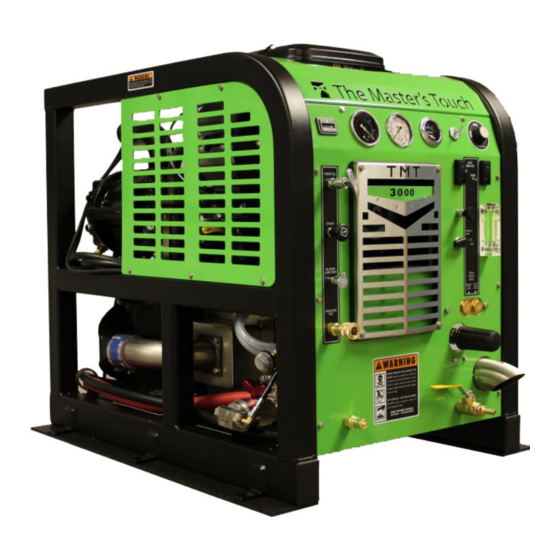
TMT 3000
Owner's Manual
HydraMaster North America, Inc.
11015 47
Avenue West, Mukilteo, Washington 98275
th
MAN-44128 Rev. 0, May 7, 2010
(000-182-500)
No part of this manual may be reproduced or used in any form or by any means (i.e. graphic, electronic, photocopying
or electronic retrieval systems) without the express written permission of HydraMaster North America, Inc.
All rights reserved. © 2010 HydraMaster North America, Inc.
Advertisement
Table of Contents

Related Manuals for HydraMaster The Master's Touch TMT 3000


Summary of Contents for HydraMaster The Master's Touch TMT 3000
- Page 1 No part of this manual may be reproduced or used in any form or by any means (i.e. graphic, electronic, photocopying or electronic retrieval systems) without the express written permission of HydraMaster North America, Inc. All rights reserved. © 2010 HydraMaster North America, Inc.
-
Page 2: Table Of Contents
Table of Contents GeNeRAl INfORMATION ................SeCTION 1 System Concept ..................1-3 Contact Information ................. 1-4 Warnings, Cautions and Notices ............. 1-5 Responsibilities ..................1-9 Machine Specifications ................1-12 High Altitude Operation ................1-14 local Water Precautions ................. 1-14 INSTAllATION INfORMATION ..............SeCTION 2 Operating the TMT 3000 in Hot Weather .......... - Page 3 eleCTRICAl SySTeM ................SeCTION 7 SySTeMS TROuBleSHOOTING ............... SeCTION 8 Heating System ..................8-2 Chemical System ..................8-3 engine ..................... 8-4 High Pressure System ................8-8 Vacuum System ..................8-10 MACHINe ASSeMBlIeS AND PARTS lIST ..........SeCTION 9 Machine Assembly Parts list ..............9-4 frame Assembly Parts list ..............
- Page 4 WARRANTy INfORMATION ............... SeCTION 11 Blower ....................11-1 High Pressure Water Pump ..............11-1 Vacuum Tank ..................11-1 Chemical System ..................11-1 Control Panel ..................11-1 Vacuum and Solution Hoses ..............11-2 Cleaning Wand and Tool ................. 11-2 Water Heating System ................11-2 Hard Water Deposits ................
- Page 5 list of figures figure 1-1. Hard Water Map of Mainland united States ........1-15 figure 2-1. location of Roof Vents in Vehicle ............2-1 figure 2-2. Recommended location of TMT 3000 in Van ........2-3 figure 2-3. Install fuel Pump, Outlet Side up............2-6 figure 2-4.
- Page 6 figure 6-1. Annotated Water, Chemical and Solution flow Diagram - View 1 of 2 ............6-3 figure 6-2. Annotated Water, Chemical and Solution flow Diagram - View 2 of 2 ............6-4 figure 6-3. Chemical flow Diagram - larger View ..........6-5 figure 6-4. exhaust flow Diagram................6-6 figure 7-1.
- Page 7 1- General Information The compact but powerful TMT 3000 is a carefully engineered truckmount multi-surface cleaning machine designed and manufactured by HydraMaster North America, Inc. A 23 Hp Briggs and Stratton engine powers the TMT 3000’s Tuthill 3006 vacuum blower and the high pressure water pump, which is rated at 4 gpm (15 litres/minute).
-
Page 8: General Information
The TMT 3000 can be mounted onto a HydraMaster 85 gallon (322 litre) Rotomolded fresh Water Tank. The HydraMaster 70 gallon (265 litre) recovery tank, which comes in the standard equipment package, can be used with the 85 gallon fresh water tank installation. -
Page 9: System Concept
SySTeM COnCepT This is how the TMT 3000 works: Incoming water enters the water box and is pressurized by the high pressure water pump. The water is heated by the engine and blower exhaust in the cross flow heat exchanger. Cleaning solution is then injected into the pressurized water stream and the heated solution is delivered to the cleaning tool. -
Page 10: Contact Information
To find a local distributor, please visit our website at http://www.hydramaster.com/owners/ locate/index.asp. If your question cannot be resolved by your distributor or by the information within this manual, you may contact HydraMaster Customer Service direct using the following phone numbers. Hours Telephone numbers... -
Page 11: Warnings, Cautions And Notices
WarnIngS, CaUTIOnS anD nOTICeS HydraMaster uses this WARNING symbol throughout the manual to warn of possible injury or death. This CAuTION symbol is used to warn of possible equipment damage. This NOTICe symbol indicates that federal or state regulatory laws may apply, and also emphasizes supplemental information. - Page 12 Transporting a vented fuel container that presently contains, or has ever contained in the past, a flammable liquid is strictly forbidden by HydraMaster and by federal and state regulations. Doing so will increase the risk of fire and explosion. Serious injury or death may result.
- Page 13 Never smoke in or around the truckmount. Doing so will increase the risk of fire and explosion. Serious injury or death may result. During the operation of the truckmount the exhaust system will become extremely hot. Keep all flammable materials away from the truckmount exhaust system. Failure to do so will increase the risk of fire and explosion.
- Page 14 Never operate the truckmount with a water hardness reading measuring 3.0 grains per gallon (3.79 litres) or higher. using water with a reading of 3.0 grains per gallon or higher will cause scale to build up inside the truckmount water system. Scale build up causes serious component damage.
-
Page 15: Responsibilities
reSpOnSIBIlITIeS purchaser’s responsibilities • Prior to purchasing a van, ensure that the payload is suitable for all of the equipment that will be installed and transported. This includes and is not limited to: the truckmount, recovery tanks, fresh water tanks, on-board water, hose reels, hoses, cleaning tools, chemicals and drying equipment. - Page 16 Start and run the truckmount and check that all systems function properly. • Test all hoses, wands and other accessories for correct operation. Verify that the hoses meet or exceed HydraMaster’s specifications. • ensure timely return of the document package.
- Page 17 Training The distributor should provide a thorough review of the operation manual with the purchaser along with instruction and familiarization in: How all the truckmount’s systems function. All safety precautions and their importance. How to correctly start and shut down the truckmount. How to correctly clean with the truckmount.
-
Page 18: Machine Specifications
MaCHIne SpeCIFICaTIOnS frame Dimensions 24.0" W x 35" D x 31.5" H (61 cm x 89 cm x 80 cm) Weight 500 lbs (227 kg) engine - Briggs and Oil Type 5W-30 Synthetic Stratton 23 Hp Capacity Approx. 1 1/2 quarts, or 48 oz (1.42 litres) when changing oil and filter engine rpm... - Page 19 Heating System Stainless Steel Cross flow Heat exchanger Standard equipment Automatic Pump-Out (APO) Recovery Hose 10 ft (3.05 m). Water Box Rotomolded 3 - 4 gallon (11.4 -15 litres) capacity Recovery Tank 70 gallon universal Tank (265 litre universal Tank) Cleaning Wand/Tool Stainless Steel S-bend Replaceable Grip...
-
Page 20: High Altitude Operation
Contact the local Briggs and Stratton dealer or HydraMaster to obtain the proper jet size. find your local Briggs and Stratton dealer at http://vanguardengines.via.infonow.net/... -
Page 21: Figure 1-1. Hard Water Map Of Mainland United States
Hard Water area Map The hard water map, shown in figure 1-1, defines hard water areas in the continental United States which compromise fluid related components such as hoses, fittings, heaters, pumps, valves and water-cooled engines. for other countries, hard water area maps can be obtained from geological societies. - Page 22 Cleaning efficiency and equipment life is increased, chemical use decreased, and the appearance of cleaned carpets enhanced when water softeners are incorporated in hard water areas. HydraMaster strongly urges the use of water softener units with the TMT 3000 in areas exceeding 3.0 grains per gallon.
- Page 23 Waste Water Disposal advisory There are laws in most communities prohibiting the dumping of recovered “gray” water from carpet cleaning in any place but a sanitary treatment system. The cleaning rinse water, recovered into your unit’s vacuum tank, contains materials such as detergents, and must be safely processed before entering streams, rivers and reservoirs.
-
Page 24: Installation Information
3/4 ton capacity or a 3/4 ton HD van. If a fresh water tank is added, a one ton or larger capacity van is required. Prior to installation of the TMT 3000, HydraMaster recommends installing a spray-on bed liner in the vehicle. This provides ‘metal to cushion’ mounting rather than ‘metal to metal’... -
Page 25: Operating The Tmt 3000 In Hot Weather
OperaTIng THe TMT 3000 In HOT WeaTHer HydraMaster recommends the following steps when operating the TMT 3000 during periods of hot weather (95º f [35º C] or higher). This will help ensure that your TMT 3000 continues to run at 100% capacity during even the hottest days. -
Page 26: Figure 2-2. Recommended Location Of Tmt 3000 In Van
Use caution when drilling any holes through the van floor. Many vans have critical components mounted directly below the vehicle floor that could be damaged by a misplaced drill bit. lOCaTIng THe TMT 3000 In VeHICle There are two recommended entry points on the vehicle for the TMT 3000 installation: the side door or the rear doors. - Page 27 Protect yourself and the machine. HydraMaster strongly recommends that the exhaust from the front of the machine be vented down under the truck to prevent carbon monoxide from entering the job site.
-
Page 28: Setting Up The Tmt 3000
SeTTIng Up THe TMT 3000 Prior to operating the TMT 3000, follow these steps: Adjust the vacuum relief located on the recovery tank by capping all the vacuum inlets. The machine should be set to 12” Hg maximum. Setting the vacuum level higher than the recommended value can result in an increased risk of serious component damage. -
Page 29: Orientation Of Fuel Pump
OrIenTaTIOn OF FUel pUMp For proper fuel pump operation and fuel flow, the vehicle’s fuel pump must be installed in a lower position with respect to the fuel tank and in as vertical a position as possible (outlet side up - see figure 2-3 and figure 2-4). -
Page 30: Cleaning Information
HydraMaster strongly recommends attending an Institute of Inspection, Cleaning and Restoration Certification (IICRC) approved school as soon as possible and to always follow the IICRC guidelines when cleaning carpets or hard surfaces. -
Page 31: Precautions
HydraMaster’s ClearWater Rinse™ has been formulated to protect vital components. HydraMaster will not warranty parts that have been damaged from using acid products that have obviously caused failures. preparIng THe CarpeT FOr exTraCTIOn... -
Page 32: Rinse And Recover
This, along with any soil imbedded in the backing, will be wicked to the surface of the fibers as the carpet dries. HydraMaster recommends the following rinse aids: Alkaline - Hydra-Dri Powder™ or Hydra-Clean™. Acid - ClearWater Rinse™. OVerWeTTIng Overwetting is an annoyance to all concerned. -
Page 33: Cleaning Tool Tips
CleanIng TOOl TIpS Wands With a wand, keep cleaning strokes short, front to back, and run a “dry pass”. After pulling the wand for a strip of 3 or 4 ft (0.9 m or 1.2 m) long with the solution trigger activated, go back up to the top of the stroke, and make a “dry “... - Page 34 3-5: Cleaning Information...
- Page 35 rotary Tool: rx-20 Rotary tools are easier to move on the carpet, but harder to control at first. With a rotary tool, remember to keep strokes short and side-to-side. Before turning on the RX-20, adjust the handle; it should rest right below or even with the bottom of your pants’...
- Page 36 Upholstery Tool: DriMaster use the upholstery tool on small rugs and furniture. When you clean rugs, be sure that the temperature and chemicals are safe for that particular type of rug. As with the larger tools, do not leave the surface of the upholstery too wet. Adjust the volume of water on the tool without it touching any surface: the water should just barely come out of the tool before the vacuum pulls it back in.
-
Page 37: Operating Instructions
4 - Operating Instructions This section describes how to operate the TMT 3000, starting with a description of the dash assembly (see figure 4-1). Ignition Switch automatic pump-Out Switch Throttle Cable (HIgH and pump-In IDle) Switch Choke Chemical Metering Control knob Chemical pump Valve Figure 4-1. - Page 38 The dash assembly includes the solution temperature control dial; the temperature, vacuum and pressure gauges; and the hour meter (see figure 4-2). pressure gauge Temperature Temperature Control Dial Vacuum gauge gauge Blower lube port pressure regulator adjustment Solution (By-pass) Valve port Figure 4-2.
-
Page 39: Figure 4-3. Location Of Chemical Pump Shutoff Valve
To help achieve a high psi rating for high pressure washing, HydraMaster has added a chemical pump shutoff valve into the TMT 3000’s pump system. The shutoff valve can be accessed from the side of the machine (see 4-3). Chemical pump Shutoff Valve Figure 4-3. -
Page 40: Setting The Temperature
SeTTIng THe TeMperaTUre Depending upon the type of cleaning jobs you need to do, there will be times where you will not need the maximum heat available. To adjust the temperature, the thermostat dial can be rotated counterclockwise to reduce the temperature and rotated clockwise to increase the temperature. -
Page 41: Setting The Pressure For Cleaning Operations
SeTTIng THe preSSUre FOr CleanIng OperaTIOnS Adjust the “PReSSuRe ReGulATOR” to the desired level as follows: • Carpet Cleaning: 300 to 400 psi • Hard Surface Cleaning: up to 1,200 psi (or as indicated on tool) Valve Handle The chemical pump shutoff valve can be turned on for cleaning operations at 1,200 psi or lower. -
Page 42: Setting The Pressure For High Pressure Washing Operations
SeTTIng THe preSSUre FOr HIgH preSSUre WaSHIng OperaTIOnS The chemical pump shutoff valve must be turned off during high pressure washing operations. Valve Handle The chemical pump shutoff valve is off when the handle of the integrated valve is perpendicular to the pump (see figure 4-5). -
Page 43: Shut Down Procedure
Cap off the inlet(s) to the vacuum tank. Spray a HydraMaster-recommended spray lubricant into the “BlOWeR luBe PORT” for about 5 to 10 seconds while the unit is running. uncap the inlet(s) and run the unit for another minute to allow the blower to cool down. -
Page 44: Machine Maintenance
A maintenance log, provided in the Owner’s Guide, must be correctly and completely filled out. HydraMaster may request to inspect the logs before a warranty claim is honored. It is recommended that the log be affixed to the vehicle door near the truckmount for convenience and to serve as a maintenance reminder. -
Page 45: Operational Maintenance
Inspect the truckmount for water and oil leaks, loose electrical connections, etc. and repair as needed. • lubricate the blower with a HydraMaster-recommended lubricant. Weekly Maintenance • Inspect the recovery tank filters for tears, holes, etc. Repair or replace as needed. -
Page 46: Overall Machine Maintenance
OVerall MaCHIne MaInTenanCe Maintenance, troubleshooting and repair are much easier tasks to accomplish on a clean truckmount. Regular cleaning of the truckmount offers the user an opportunity to visually inspect all facets of the truckmount and spot potential problems before they occur. In addition to the operational maintenance the following “housekeeping”... -
Page 47: Engine Maintenance
engIne MaInTenanCe engine Oil level Check The engine oil level should be checked daily. It is recommended that the oil be checked just before the engine is started for the first time for that day. The oil level should be between the ‘Add’... - Page 48 Oil Filter Briggs and Stratton engines use a Briggs and Stratton filter. An equivalent or better oil filter must be used when servicing the engine. To replace the filter, use a proper filter wrench to remove the filter. Clean the filter mounting base and lightly coat the gasket surface of the new filter with engine oil.
-
Page 49: High Pressure Pump Maintenance
HIgH preSSUre pUMp MaInTenanCe Daily Check the oil level and the condition of the oil. The oil level should be up to the center of the sight glass on the side or rear of the pump or between the “MIN” and “MAX” lines on the dipstick. -
Page 50: Figure 5-1. Remove Valve Cap And Valve Assembly
Servicing Valves on the High pressure pump Removing a Valve Remove the valve cap (30 mm) and extract the valve assembly (see figure 5-1). Figure 5-1. remove Valve Cap and Valve assembly Remove the valve assembly (retainer, spring, valve plate, valve seat) from the valve cavity. -
Page 51: Figure 5-3. Replace Center Inlet Check Valve With Modified Check Valve
Replace center inlet check valve with modified check valve (P/N 000-169-212 - figure 5-3). Modified Check Valve Figure 5-3. Replace Center Inlet Check Valve With Modified Check Valve Apply O-ring grease to O-rings and install valves (figure 5-4). Replace valve cap and torque to 95 ft. lbs.(13 m kgs) see figure 5-5). -
Page 52: Figure 5-6. Separate Manifold From Crankcase
Remove the fasteners retaining the manifold Separate manifold from crankcase (see figure 5-6). Figure 5-6. Separate Manifold from Crankcase It may be necessary to rotate crankshaft or tap manifold with rawhide or plastic mallet to loosen. When sliding manifold from crankcase, use caution not to damage ceramic plungers. -
Page 53: Figure 5-9. Remove Stainless Steel Plunger Bolt And Ceramic Plunger
Remove the stainless steel plunger bolt and ceramic plunger from the plunger guide (see figure 5-9). If the slinger washer is removed, be certain it is re-installed or replaced. Separate plunger bolt from ceramic plunger (see figure 5-9). Figure 5-9. remove Stainless Steel plunger Bolt and Ceramic plunger Install new Teflon back-up ring and O-ring on the plunger bolt. -
Page 54: Figure 5-11. Extract Retainers And Seals
extracting Seals With manifold removed from crankcase: Insert proper extractor collet through main seal retainer (see figure 5-11). Tighten collet and extract retainers and seals. The Teflon seals of the HT series will be damaged during disassembly so new ones with have to be installed. Figure 5-11. -
Page 55: Figure 5-12. Seal Kit And Insertion Tool For Seal Installation
Replacing the Seal Assemblies Only one seal kit (P/N 078-518) is necessary to repair all the seals in the pump (see figure 5-12). use an insertion tool for seal installation Figure 5-12. Seal kit and Insertion Tool for Seal Installation To install a seal assembly: Apply a film of O-ring grease on the O-ring on the outside of the new high pressure seal. -
Page 56: Figure 5-14. Install Retainers Into Cavities
To install the intermediate retainers and the low pressure seals: Insert the brass intermediate retainer into the cavity. Press the new low pressure seal into the brass low pressure seal retainer and install a new O-ring on the outside (see figure 5-14). Figure 5-14. -
Page 57: Figure 5-16. Re-Install Manifold And Torque Fasteners
Re-Installing Manifold Position the outer plungers at the same position (see figure 5-16). Re-install manifold and torque the fasteners in an “X” pattern to 50% of specification and then retorque to 100% specification (see figure 5-17 and figure 5-18). Figure 5-16. re-install Manifold and Torque Fasteners Figure 5-17. -
Page 58: Vacuum System Maintenance
Cap off the inlet(s) to the vacuum tank. Spray a HydraMaster-recommended spray lubricant into the “BlOWeR luBe PORT” for about 5 to 10 seconds while the unit is running. uncap the inlet(s) and run the unit for another minute to allow the blower to cool down. -
Page 59: Descaling Procedure (Required)
DeSCalIng prOCeDUre (reQUIreD) Scale deposits on the interior of the heating system can cause a noticeable loss in heating performance. Deposits of this kind result from hard water. The frequency with which descaling procedures are required will vary. If the area has particularly hard water, you may have to descale often. -
Page 60: Freeze Guarding
Freeze gUarDIng To avoid permanent damage to the truckmount, it is imperative to follow the freeze Guard Procedure whenever the possibility of freezing temperatures exists. When disposing of antifreeze, follow local laws and regulations. Do not discard into storm sewers, septic systems or onto the ground. Antifreeze is harmful or fatal if swallowed. - Page 61 The reclaimed antifreeze solution may be used three times before being discarded. To freeze guard the hoses and wand, perform Step 7 in the preceding procedure with the items to be freeze guarded attached. Always check the freezing level of your reclaimed antifreeze with a glycol tester before reusing.
-
Page 62: Tensioning The Pump Drive Belt
TenSIOnIng THe pUMp DrIVe BelT Remove the TMT 3000 grill to gain access to the idler pulley. Remove the engine duct plate. do not remove the ½”-13 x 2 ¼” long bolt on the idler pulley. loosen but Remove the right cover of the machine to gain access to the tensioning screw. Adjust the tension of the belt by turning the ¼”-20 x 4”... -
Page 63: Water And Chemical System
6 - Water and Chemical System This section describes the TMT 3000’s water and chemical systems, and includes the exhaust subsystem. Parts of the text are also included in the section’s annotated illustrations which are referenced in the following paragraphs (see figure 6-1 – figure 6-4). The process starts when fresh water is brought through the front of the truckmount into the water box, as indicated in figure 6-1. - Page 64 (see figure 6-2). The chemical is pressurized by the HydraMaster diaphragm chemical pump attached to the head of the water pump. This pump pulls the chemical from the chemical, or soap, jug through the chemical flow meter (see figure 6-3).
-
Page 65: Figure 6-1. Annotated Water, Chemical And
Figure 6-1. annotated Water, Chemical and Solution Flow Diagram - View 1 of 2 8069 1. Fresh water is brought through the front of the truckmount into the water box. 2. pressurized water enters the by- pass valve. This valve allows manual adjustment of the pressure level. -
Page 66: Figure 6-2. Annotated Water, Chemical And
Figure 6-2. annotated Water, Chemical and Solution Flow Diagram - View 2 of 2 8069 6. The water that is being called for by the wand then exits the manifold and passes through a 4. Water temperature check valve. is controlled via a temperature sensor inside the high pressure manifold. -
Page 67: Figure 6-3. Chemical Flow Diagram - Larger View
Chemical Flow Diagram - larger View 8069 The chemical is pressurized by the HydraMaster diaphragm chemical pump attached to the head of the water pump. This pump pulls the chemical from the chemical, or soap, jug through the chemical flow meter. After being pressurized, the chemical travels through the metering valve and is injected into the high pressure stream. -
Page 68: Figure 6-4. Exhaust Flow Diagram
Figure 6-4. exhaust Flow Diagram 8069 Water and Chemical System: 6-6... -
Page 69: Electrical System
7 - electrical System This section includes drawings for the following: electrical Schematic (see figure 7-1) „ Wiring Diagram ( figure 7-2 - figure 7-4) „ The TMT 3000 electrical system operates on 12 V DC which is provided by the battery. Battery levels are maintained by a 20 Amp alternator that is built into the engine. -
Page 70: Figure 7-1. Electrical Schematic
ReVISION CODe DATe CHKD APPVD TeMPeRATuRe GAuGe TI-1 Figure 7-1. electrical CONTROlleR Schematic SeNSOR SW-5 TeMPeRATuRe 8068 SeNDeR TT-1 B&S ENGINE MTR-1 TeMPeRATuRe CONTROlleR CARB TC-1 SOleNOID eNGINe SHuTDOWN eNGINe KIll luG RelAy CR-1 STARTeR STATOR HIGH TeMP THeRMOSTAT STARTeR SOleNOID TS-1 SOleNOID... - Page 71 REVISIONS Figure 7-2. Wiring Diagram - View 1 of 3 8067 B&S ENGINE MTR-1 1 (RED) 1 (RED) FRESH WATER PUMP IN (OPTIONAL) 2 (BLK) 2 (BLK) TO SW1-3 (16 GA) (SHEET 3) CARB 3 (YEL) TO CR1-#87 (SHEET 2) SOLENOID 35(WHT/BLK) (BLK)
- Page 72 Figure 7-3. Wiring Diagram - View 2 of 3 35 (ORG) 16 GA. TO IGNITION SW1-1 (SHEET 3) 8067 6 (ORG) TO SOL 1-BATT (SHEET 1) 34 (BRN) 14 GA TO APO SWITCH SW3- #3 (SHEET 3) 7 (ORG) TO SOL 1-BATT (SHEET 1) FUSE 3(YEL) TO ENGINE STOP LUG 3 (YEL)
- Page 73 TEMPERATURE THERMOSTAT IGNITION SWITCH GAUGE TS-1 TO TB1-6 (SHEET 2) 17(WHT/ORG) SW-1 TI-1 Figure 7-4. Wiring Diagram - View 3 of 3 TO TB1-1 (SHEET 2) 18(BLK/WHT) 8067 HOUR METER HI-1 91(RED) TO TB1-3 (SHEET 2) 90(WHT) TO TB1-4 (SHEET 2) 23(PNK) TO CR-1 #86 (SHEET 2) 24(PNK) TO TB1-2 (SHEET 2) 26 (WHT) - TO CONTROLLER TR-3 20 GA (SHEET 2)
-
Page 74: Systems Troubleshooting
8 - Systems Troubleshooting This section describes the standard troubleshooting procedures in the following areas: Heating System „ Chemical System „ engine „ High Pressure System „ Vacuum System „ 8-1: Systems Troubleshooting... -
Page 75: Heating System
HeaTIng SySTeM 1.0 Truckmount overheats and shuts down 1.1 The orifice or filter screen Remove and inspect. Clean as necessary. are restricted. 1.2 The dump solenoid is Inspect the solenoid and the hose that delivers restricted. water to it. Clean or replace as necessary. 1.3 The dump solenoid is Check the main fuse. -
Page 76: Chemical System
CHeMICal SySTeM 1.0 System will not prime 1.1 The check valves in Remove the valves and inspect. Clean or replace as chemical pump are faulty. necessary. 1.2 The chemical pump Remove and inspect. Replace as necessary. diaphragm is faulty. 1.3 The check valve in high Remove the valve and inspect. -
Page 77: Engine
engIne 1.0 Will not turn over 1.1 A loose or corroded Clean and tighten the battery terminal connections. battery terminal. 1.2 The battery is dead. Recharge or replace the battery. Test the charging system. Repair if necessary. Do not attempt to jump start the truckmount from a running vehicle. - Page 78 2.0 Turns over but will not start; there is no spark. (To check for spark, refer to engine manual.) 2.1 The recovery tank is full. Drain the tank. 2.2 The recovery tank float is Inspect the float. Repair or replace as necessary. faulty.
- Page 79 4.0 Will not come up to normal operating rpm. Note: engine should be adjusted to run at 3,200 rpm under no vacuum load. 4.1 The throttle linkage is out Inspect for broken or loose linkage. Repair or replace of adjustment. as necessary.
- Page 80 7.0 engine overheats 7.1 Poor ventilation in the van. Open all the van doors. Install a roof vent in the van. Remove any dividers or other objects impeding airflow around the truckmount. 7.2 low oil level. Check the level and fill as necessary. Running the engine with a low oil level can cause severe damage to the engine.
-
Page 81: High Pressure System
HIgH preSSUre SySTeM 1.0 The pump will not come up to normal cleaning pressure 1.1 The pressure adjusting Inspect the valve. Repair or replace if necessary. valve is faulty. 1.2 Worn seals or valves in Test the pump output volume directly from the pump the pump. - Page 82 4.0 pressure pulsation 4.1 Air leak between the water Check all the hoses and fittings for cuts, breaks, box and pump. cracks, etc. Repair as necessary. 4.2 The check valve(s) in the Remove each valve and inspect for correct pump are faulty. operation.
-
Page 83: Vacuum System
VaCUUM SySTeM 1.0 a weak vacuum at wand. The gauge reads normal. 1.1 Blockage in the hoses or Disconnect the hoses and check for an obstruction. wand tube 1.2 excessive length of Do not attach excessive lengths of hose. hose connected to the truckmount 2.0 a weak vacuum 2.1 Air leak somewhere in the... - Page 84 5.0 The vacuum blower is locked and will not turn 5.1 Truckmount has been Spray penetrating oil into the blower and let sit for inactive for a period of at least 1 hour. Then very carefully use pipe wrench time and the blower was on the outer diameter of the pulley on the coupler not properly lubricated to attempt to free lobes of the blower.
-
Page 85: Machine Assemblies And Parts List
9 - Machine Assemblies and Parts list This section contains all the assemblies and parts lists associated with the TMT 3000: Machine Assembly Parts lis Water Box Assembly Parts lis „ „ frame Assembly Parts lis exhaust Assembly Parts lis „... - Page 86 Figure 9-1. Machine assembly - View of 1 of 2 8050 Machine Assemblies and Parts lists: 9-2...
- Page 87 Figure 9-2. Machine assembly - View of 2 of 2 8050 9-3: Machine Assemblies and Parts lists...
-
Page 88: Machine Assembly Parts List
Machine assembly parts list Item part number Description Item part number Description - - - Assembly, frame 000-143-126 Screw, #10-24uNC X 0.50” lg. Hex Head 000-041-451 Cover, Side - 19.900” X 14.316” 000-174-001 Washer, #10 flat 000-041-452 Cover, Side - 17.250” X 14.316” 000-174-014 Washer, #10 lock 000-041-490... - Page 89 Figure 9-3. Frame assembly - View 1 of 4 8051 9-5: Machine Assemblies and Parts lists...
- Page 90 Figure 9-4. Frame assembly - View 2 of 4 8051 45 41 FRONT DASH, PART OF FRAME AND 3" OUTLET HOSE HIDDEN Machine Assemblies and Parts lists: 9-6...
- Page 91 Figure 9-5. Frame assembly - View 3 of 4 8051 9-7: Machine Assemblies and Parts lists MID FRAME RAIL HIDDEN...
- Page 92 Figure 9-6. Frame assembly - View 4 of 4 8051 Machine Assemblies and Parts lists: 9-8 MID FRAME RAIL HIDDEN...
-
Page 93: Frame Assembly Parts List
Frame assembly parts list Item part number Description Item part number Description - - - Assembly, Blower 000-068-018 Hose, 1/2” I.D. - Bulk - - - Assembly, Water Box 000-068-018 Hose, 1/2” I.D. - Bulk - - - Assembly, electrical Panel 000-068-018 Hose, 1/2”... - Page 94 Figure 9-7. engine assembly - View 1 of 2 8052 Rev. A Machine Assemblies and Parts lists: 9-10...
- Page 95 Figure 9-8. engine assembly - View 2 of 2 8052 Rev. A 9-11: Machine Assemblies and Parts lists...
-
Page 96: Engine Assembly Parts List
engine assembly parts list Item part number Description Item part number Description 000-105-562 Plate, engine Duct - - - filter, B&S fuel (Comes w/ engine) - - - Hose, fuel (Comes w/ engine) 000-106-009 Plug, 1/8” NPT Allen Head 000-020-025 Bushing, H X 1”... - Page 97 Figure 9-9. pump assembly - View 1 of 2 8053 9-13: Machine Assemblies and Parts lists...
-
Page 98: Pump Assembly Parts List
WASHER, 5/16" S/S LOCK WASHER, 5/16" FLAT VALVE, GP PUMP CHECK - MOD. - 4.0 GALLON VALVE, HIGH PRESSURE SAFETY (2200) Figure 9-10. pump assembly - View 2 of 2 pump assembly parts list SCREW, M8 x 16MM LG. SOCKET HEAD 8053 SCREW, 5/16"-18UNC x 2.5"... -
Page 99: Figure 9-11. Dash Assembly
Figure 9-11. Dash assembly 8054 9-15: Machine Assemblies and Parts lists... -
Page 100: Dash Assembly Parts List
Dash assembly parts list Item part number Description Item part number Description 000-074-017 Gauge, 30” Hg. Vacuum - HydraMaster - - - Assembly, Bypass Valve - - - Assembly, Hi PSI Manifold 000-074-030 Meter, Chemical flow Raw - - -... - Page 101 Dash assembly parts list (continued) Item part number Description Item part number Description 000-174-007 Washer, 1/2” flat 000-174-058 Washer, 21/32” I.D. X 27/32” O.D. Nylon 000-174-008 Washer, 5/8” flat 000-174-062 Washer,1/2” I.D. X 3/4” O.D. X 0.010” Thk 000-174-014 Washer, #10 lock label, Dash Warning 000-174-022 Washer, 7/16”...
-
Page 102: Electrical Panel Assembly Parts List
electrical panel assembly parts list Figure 9-12. electrical panel assembly 7020 Rev. C Item part number Description 000-100-171 Panel, electrical - 7" X 7.25" 000-074-125 Controller, Temp Single Analog Input - RTD 000-056-006 fuse Holder, In-line - Weatherproof 000-157-022 Switch, Relay 000-084-010 light, Green leD Indicator Mini 000-012-002... -
Page 103: Blower Heat Exchanger Assembly Parts List
REVISIONS REVISION CODE DATE Figure 9-13. Heat exchanger assembly 8055 Blower Heat exchanger assembly parts list Item part number Description Item part number Description 000-013-072 Box, Inlet Plenum - Weldment 000-052-766 elbow, 3/8 NPT X 3/8 JIC 000-013-073 Box, Outlet Plenum - Weldment 000-106-008 Plug, 3/8”... -
Page 104: Blower Assembly Parts List
REVISIONS REVISION CODE DATE CHKD APPVD ITEM 4 WAS 052-083; ITEM 5 WAS 068- ECR #1754 4/27/2010 L.O.L. C.I.R. ECRB 219; ADDED ITEM 10-11. ITEM 9 WAS 143-018; ADDED ITEM 11; 5/11/2010 L.O.L. C.I.R. C.I.R. ECR #1754 RENUMBERED BOM; WAS CSIZE. Figure 9-14. -
Page 105: Silencer Assembly Parts List
Figure 9-15. Silencer assembly Silencer assembly parts list 8056 REVISIONS Item part number Description REVISION CODE DATE CHKD APPVD 000-033-012 Clamp, Size #44 Hose 000-068-104 Hose, Ø 2.5” I.D. Silicone X 2.5” lg. 000-068-889 Hose, Ø 2.5” I.D. Orange Silicone X 2.5” lg. 000-093-108 Silencer, Ø2.5”... -
Page 106: Figure 9-16. Water Box Assembly
ITEM 4 WAS 052-105 & QTY. 2; ITEM 7 WAS 052-085; 5/12/2 ECR #1754 REVISION CODE DATE RENUMBERED BOM; WAS DSIZE. ITEM 1 WAS PART NO. SEE NOTES. DELETE NOTE ECR #1463 4/29/20 ITEM 4 WAS 052-105 & QTY. 2; ITEM 7 WAS 052-085; 5/12/20 ECR #1754 RENUMBERED BOM;... -
Page 107: Water Box Assembly Parts List
Water Box assembly parts list Item part number Description Item part number Description 000-068-326 Hose, 3/8” Clr w/ Braid 000-033-003 Clamp, Size #4 Mini Hose 000-041-005 Cover, 6” 000-094-097 Nut, 1”-14uns Brass 000-052-023 Tee, 3/8” NPT Male Street 000-097-041 O-Ring, 1/2” Bulk Head 000-143-017-1 Screw, 3/8”-16uNC X 3/4”... -
Page 108: Exhaust Assembly Parts List
Figure 9-17. exhaust assembly 8057 exhaust assembly parts list Item part number Description 000-001-116 Adapter, N1.50” f Slip To flare 000-033-068 Clamp, 1-1/2” exhaust 000-057-010 Gasket, exhaust Manifold - Vanguard 000-057-177 Gasket, exhaust Donut 1.50” 000-057-209 Gasket, Ø2.5” X 3.5” BCD 000-057-212 Gasket, Half Donut 000-090-071... -
Page 109: Idler Pulley Assembly Parts List
REVISIONS REVISION CODE DATE CHKD APPVD Figure 9-18. Idler pulley assembly 8058 Idler pulley assembly parts list Item part number Description Item part number Description 000-015-942 Bracket, Idler Tension 000-143-376 Screw, 1/4-20uNC X 4” lg. S/S- full Thread 000-094-009 Nut, 1/4”-20uNC Nylock 000-154-049 Spacer, Pump Idler WASHER,1/2"... -
Page 110: Hi Pressure Manifold Assembly Parts List
Figure 9-19. Hi pressure Manifold assembly REVISIONS 8059 REVISION CODE DATE CHKD APPVD Hi pressure Manifold assembly parts list ORIFICE, Ø0.021 1/8" Item part number Description Item part number Description ORIFICE, SET SCREW SPRING, 0.540 O.D. x 000-049-016 filter, 1/4” NPT Replacement “y” 000-090-010 Manifold, Hi-PSI SENSOR, RTD COMP... -
Page 111: By-Pass Valve Assembly Parts List
REVISIONS REVISION CODE DATE CHKD APPVD A ROTATED ITEM 2 180°. LRIP 5/12/2010 L.O.L. C.I.R. C.I.R. Figure 9-20. By-pass Valve assembly 8060 Rev. A By-pass Valve assembly parts list Item part number Description 000-015-515 Bracket, Cat By-Pass Valve Mount 000-169-197 Valve, PSI Regulator 0 - 3,200 psi - Modified 000-106-008 Plug, 3/8”... -
Page 112: Figure 9-21. Dura-Flow Apo Assembly
Figure 9-21. Dura-Flow apO assembly 5652C REVISIONS REVISION CODE DATE CHKD APPVD B ADDED DWG # TO ITEM 19. ECR #856 10/13/2005 L.O.L. C.I.R. C.I.R. C ADDED ITEMS 27-28. 4/16/2010 L.O.L. C.I.R. ECRB ECR #1676 KIT, JABSCO SEAL (REPLACEMENT) VARIOUS 000-078-517 - - - RUBBER... -
Page 113: Dura-Flow Apo Assembly Parts List
Dura-Flow apO assembly parts list Item part number Description Item part number Description 000-012-011 Block, 6 Post Terminal 000-091-042 Motor, Bison 438 Series 000-015-890 Bracket, Tank Mounted APO Support 000-094-027 Nut, #10-24uNC Hex 000-015-891 Bracket, APO Clamp 000-094-113 Nut, 1/4”-20uNC Neoprene Wellnut 000-027-014 Cap, Garden Hose 000-111-169... - Page 114 Figure 9-22. 70 gallon Universal recovery Tank assembly 8061 8X HIDDEN 8X HIDDEN 2X HIDDEN 2X HIDDEN 30 2X 2X HIDDEN 2X HIDDEN DETAIL A NOTES: REFERENCE BOM P/N 610-003-025. Machine Assemblies and Parts lists: 9-30 PART OF LABEL SET P/N 000-081-039 ITEM'S 26 &...
-
Page 115: 70 Gallon Universal Recovery Tank Assembly Parts List
70 gallon Universal recovery Tank assembly parts list Item part number Description Item part number Description 000-001-134 Adapter, Tank To Ø2.5” X 90° Blower Hose 000-094-113 Nut, 1/4”-20uNC Neoprene Wellnut 000-012-002 Block, 6 Post Terminal 000-106-019 Plug, 1-1/2” NPT 000-015-932 Bracket, flat filter Securing 000-106-046 Plug, 1-1/4”... -
Page 116: Machine Hose Routings
Machine Hose routings Hose routing part no. Description From 000-068-737 3/8” X 14.5” lg. - Throb High Pressure Pump By-pass Valve 000-068-888 3/16” X 24” Lg. Teflon (JIC Ends) High Pressure Pump Pressure Gauge 000-068-641 3/8” X 10” Lg. Teflon (JIC Ends) By-pass Valve Heat exhaust Inlet 000-068-737... -
Page 117: 10 - How To Order Parts
We shall always endeavor to be fair in our evaluation of your warranty claim and shall provide you with a complete analysis of our findings. HydraMaster warranty covers only defective materials and/or workmanship for the periods listed. Diagnostic reimbursement is specifically excluded. - Page 118 Such causes listed in this section shall constitute abuse or neglect. BlOWer • failure to lubricate impellers daily with a HydraMaster-recommended lubricant, to lubricate bearings, to maintain proper oil levels, or to use the correct oil grade and viscosity as recommended in the blower manual.
- Page 119 Guide. If you have moved to a new area or have purchased a used machine and need information regarding your local distributor, call HydraMaster at (425) 775-7272 or email us at: custsvc@hydramaster.com. When calling your distributor, be sure to have the machine’s information; model and serial number, ready for the service representative.
Need help?
Do you have a question about the The Master's Touch TMT 3000 and is the answer not in the manual?
Questions and answers