NuAire XBOXER XBC Series Installation Operating And Maintenance Istructions
Ecosmart connect control (co)
Hide thumbs
Also See for XBOXER XBC Series:

Related Manuals for NuAire XBOXER XBC Series


Summary of Contents for NuAire XBOXER XBC Series
- Page 1 XBOXER XBC UNIT SIZES 75 & 85 WITH ECOSMART CONNECT CONTROL (CO) INSTALLATION, CONTROL DETAILS, OPERATING AND MAINTENANCE FOR THE COMPLETE VENTILATION SOLUTION COMPLIANT 2 16 07. 04. 16. Leaflet Number 671736...
- Page 2 XBOXER XBC ECOSMART CONNECT CONTROL (CO) GENERAL INDEX PAGE • HORIZONTAL UNITS INSTALLATION, OPERATING & MAINTENANCE INSTRUCTIONS 4 - 12 • VERTICAL UNITS INSTALLATION, OPERATING & MAINTENANCE INSTRUCTIONS 13 - 19 • DESCRIPTION OF CONTROL 20 - 53 • CONTROL & PCB LAYOUTS 54 - 69 •...
- Page 3 XBOXER XBC 75 & 85 VERTICAL UNIT - COMMISSIONING & SETTING TO WORK • XBOXER XBC 75 & 85 VERTICAL UNIT - SPARE PARTS • XBOXER XBC 75 & 85 VERTICAL UNIT - ANCILLARIES, DIMENSIONS & WEIGHTS 18 - 19 nuaire.co.uk 07. 04. 16. Leaflet Number 671736...
- Page 4 XBOXER XBC ECOSMART CONNECT CONTROL (CO) The EMC Directive 2004/108/EC SUPPLY & EXTRACT VENTILATION UNIT The Low Voltage Directive 2006/95/EC WITH HEAT RECOVERY INSTALLATION, OPERATING & MAINTENANCE INSTRUCTIONS INTRODUCTION - XBOXER XBC 75 & 85 CODE DESCRIPTION: XBOXER XBC 75 & 85 HORIZONTAL HORIZONTAL ECOSMART (CO) MODELS VENTILATION UNITS The information contained in this document provides details of...
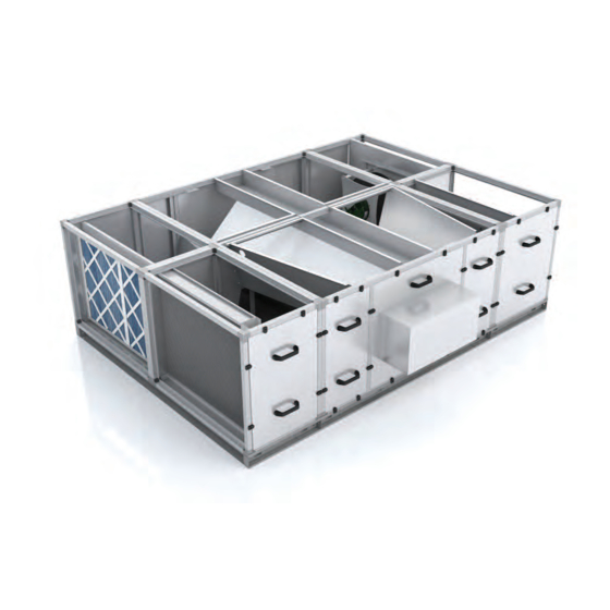
- Page 5 Figure 3: Horizontal unit access and configuration. Standard (left hand) unit shown. Intake Counterflow Heat Exchanger G4 Filter Exhaust Extract from room 8mm outside dia. condensate drain. Condensate pump fitted as standard Control with alarm facility Supply to room LPHW or Electric Heater Battery nuaire.co.uk 07. 04. 16. Leaflet Number 671736...
- Page 6 All claims for damage and/or incomplete delivery must be reported to Heat recovery components and modules that incorporate cooling coils Nuaire within two days of receipt of the equipment. may produce condensation during use. 2.1 OFF LOADING AND HANDLING FROM THE An insulated drip tray and condensate pump is provided.
- Page 7 All models - the weather roof is part of the unit code and is factory fitted only. Example: XBC85-H-LATWP. *Includes unit and base rail. nuaire.co.uk 07. 04. 16. Leaflet Number 671736...
- Page 8 5.0 XBOXER XBC75 & 85 HORIZONTAL (CO) MOTORISED DAMPERS Internal version (example code: XBC75-H-MD24V). If Nuaire matched silencers (example code XBC75-H-SIL900) are being fitted to the fan unit, the motorised damper (example code XBC75-H-MD24V) needs to be fitted after the silencers.
- Page 9 Isolation - Before commencing work make sure The completed installation (including the connections within the unit, that the unit, switched live and Nuaire control are electrically isolated from the mains supply. as these may be disturbed during installation) shall be pressure tested to the project engineer’s specification.
- Page 10 XBOXER XBC ECOSMART CONNECT CONTROL (CO) 7.0 XBOXER XBC75 & 85 HORIZONTAL (CO) SPARE PARTS Ensure correct model is selected: XBC75 – HORIZONTAL PART NO. DESCRIPTION XBC75-H-FILTERKIT Replacement G4 panel filters x 4 776187 Replacement Blower assembly x 1 XBC85 – HORIZONTAL PART NO.
- Page 11 G4 Bag with weather roof 2000 1001 XBC85- G4B- HWP G4 Bag with weather roof 2000 1001 XBC75- G4B- HRWP G4 Bag with weather roof 2000 1001 XBC85- G4B- HRWP G4 Bag with weather roof 2000 1001 nuaire.co.uk 07. 04. 16. Leaflet Number 671736...
- Page 12 XBC85-FCE-RCO-H Electric side by side module with base frame for Ecosmart Connect models (CO) 2000 Above is an indicative list of XBC75 & 85 ancillaries, for further details please contact Nuaire. Note: Codes with ‘R’ i.e. (XBC75-G4B-HR) refer to right hand unit versions.
- Page 13 3. V = Vertical 4. Attenuator SIL900 = 900 mm length Attenuator SIL900WP = 900 mm length with weather roof Figure 10: Layout Overview of the XBC vertical unit viewed with side panels removed removed. nuaire.co.uk 07. 04. 16. Leaflet Number 671736...
- Page 14 XBOXER XBC ECOSMART CONNECT CONTROL (CO) 9.0 XBOXER XBC (CO) VERTICAL UNIT ACCESS Figure 11: The unit must be installed with at least 650mm clearance from a wall / barrier to gain access from the side. Isolate before removing panels. All access panels are located on one side of the fan unit Note: Unit must be isolated before panels are removed.
- Page 15 11.0 XBOXER XBC75 & 85 VERTICAL (CO) MOTORISED DAMPERS Internal version (example code: XBC75-V-MD24V). If Nuaire matched silencers (example code XBC75-H-SIL900) are being Fully interlocking parallel blades, half inch diameter electroplated fitted to the fan unit, the motorised damper (example code mild steel spindle.
- Page 16 Isolation - Before commencing work make sure The completed installation (including the connections within the unit, that the unit, switched live and Nuaire control are as these may be disturbed during installation) shall be pressure tested electrically isolated from the mains supply.
- Page 17 Remove retaining plate & slide filters out to replace slide filters out to replace Blower assemblies. Remove 4 x fixings & slide out to replace Caution - Blower Weight XBC75 - 18kg and XBC85 - 37kg nuaire.co.uk 07. 04. 16. Leaflet Number 671736...
- Page 18 XBOXER XBC ECOSMART CONNECT CONTROL (CO) 14.0 XBOXER XBC75 & 85 VERTICAL (CO) ANCILLARY DIMENSIONS (MM) AND WEIGHTS Figure 17: Vertical Unit ancillary key. WEATHER KIT Ref No. Unit Code Description Dimensions Weight Width Height Length (kg) XBC75- V- ***WP Unit with weather roof 1476 2500...
- Page 19 Electric double deck module with base frame for Ecosmart Connect models (CO) 1000 1676 Above is an indicative list of XBC75 & 85 ancillaries, for further details please contact Nuaire. Note: Codes with ‘R’ i.e. (XBC75-G4B-R) refer to right hand unit versions.
-
Page 20: Table Of Contents
XBOXER XBC ECOSMART CONNECT CONTROL (CO) INDEX - DESCRIPTION OF CONTROL PAGE • GENERAL • CONTROLLABLE ITEMS • ENABLE SIGNAL • ROOM MODULES & CONTROL FUNCTIONS 21 - 24 • EXPOSED BACNET OBJECT LIST (BY CATEGORY) 25 - 29 • NETWORKING •... -
Page 21: General
There is a non-adjustable minimum run-on time of 15mins for Room Module PIRs. This is in addition to 15.2 THE NUAIRE UNIT CONTAINS THE FOLLOWING any software run-on times. CONTROLLABLE ITEMS: 15.4.2 RM 3-SPEED FAN OVERRIDE (ESCO-TDFS ONLY) - Page 22 XBOXER XBC ECOSMART CONNECT CONTROL (CO) 15.0 DESCRIPTION OF CONTROL SOFTWARE STRATEGY 15.4.3 RM OCCUPANCY DISPLAY Function Description Available Ranges 0-10V 0-10V is scaled as defined by 0 to 50°C If an RM sensor with occupancy display is connected, it will automatically Temperature the network input 0 to 40°C...
- Page 23 Free Cooling Vent Only Bypass Heating Room Deadband Point Bypass Free Heating Cooling Vent Only Min Supply Outside Max Supply Boost Band Outside Air Temp Outside Air Temp Air Temp. Air Temp. Air Temp. nuaire.co.uk 07. 04. 16. Leaflet Number 671736...
- Page 24 XBOXER XBC ECOSMART CONNECT CONTROL (CO) 15.0 DESCRIPTION OF CONTROL SOFTWARE STRATEGY 15.8.3 OVERRIDES 15.14 ALARMS When the following conditions occur, the system will temporarily exit “Room 15.14.1 CRITICAL ALARM LATCHING Temperature Mode” and enter “Supply Temperature Mode”. Once in critical alarm state the unit will drive all heating and cooling outputs to Trickle Mode with no enable signal.
-
Page 25: Exposed Bacnet Object List (By Category)
The 0-10V signal to the supply fan 10182 Volts Extract Fan Output The 0-10V signal to the extract fan 10176 Volts Fan Enabled Cmd The state of the fan enabled relay 10191 Off/On nuaire.co.uk 07. 04. 16. Leaflet Number 671736... - Page 26 XBOXER XBC ECOSMART CONNECT CONTROL (CO) 15.0 DESCRIPTION OF CONTROL SOFTWARE STRATEGY 15.15 EXPOSED BACNET OBJECT LIST (BY CATEGORY) FAN COMMISSIONING LCD Browser BACnet Object Description Oject Object ID Default Value Units Page Type Extract Fan Max Individual fan maximum speed setting 10268 Percent Extract Fan Min...
- Page 27 The setpoint at RM address 201 10083 Degrees-Celsius RM202 Temp The temperature at RM address 202 10068 Degrees-Celsius RM202 Humidity The Humidity at RM address 202 10092 Percent-Relative-Humidity RM202 Setpoint The setpoint at RM address 202 10098 Degrees-Celsius nuaire.co.uk 07. 04. 16. Leaflet Number 671736...
- Page 28 XBOXER XBC ECOSMART CONNECT CONTROL (CO) 15.0 DESCRIPTION OF CONTROL SOFTWARE STRATEGY 15.15 EXPOSED BACNET OBJECT LIST (BY CATEGORY) ZONE SENSORS (Continued from previous page) LCD Browser BACnet Object Description Object Object ID Default Value Units Page Type RM203 Temp The temperature at RM address 203 10071 Degrees-Celsius...
- Page 29 SF Max Volt The upper voltage for the supply fan 17275 volts SF Start Volt The voltage required to start 17276 volts the extract fan SW-FAC2612-2-4A Strategy Version 17340 Off/On nuaire.co.uk 07. 04. 16. Leaflet Number 671736...
-
Page 30: Networking
XBOXER XBC ECOSMART CONNECT CONTROL (CO) 16.0 NETWORKING NETWORK CONNECTION DIAGRAM Figure 20: Ethernet IP MSTP to IP Router (Field Controller) FC bus (Sensor Actuator) SA bus (Sensor Actuator) SA bus For best results, use a linear network and switch on the EOL resistors at each end of the FC bus. 029 2085 8200... -
Page 31: Bus Devices
The shield must be earthed at the control panel end only and be made continuous along the bus length. Room Modules must not be fitted more than 150metres (cable length) from the controller. (MS/TP) nuaire.co.uk 07. 04. 16. Leaflet Number 671736... - Page 32 Figure 24: Network Settings Cancel – Quit and moves to the previous section Device Name FAD0351 TL-BRTRP-0 Device ID Nuaire XBC ESC 0909501 MAC Address Home – Shortcut to the Descriptions Field Advanced Display Nuaire XBC ESC 0909502 configured Home Page...
- Page 33 MAC Address selected in the View Config settings screen. Name Description Status Function TL-BRTRP-0 Nuaire XBC ESC 0909501 Write Nuaire XBC ESC 0909502 BACnet Device ID ** Popular object details are listed below, or use the network browser or see “Exposed BACnet Object List”...
- Page 34 Note: If the target page is selected as the home page and a security password is set the home page will be locked. The only way to exit the target screen in this case is to press the Nuaire logo to the top right of the screen for 5 seconds.
- Page 35 The only way to exit the target screen in this case is to press the Nuaire logo to the top right of the screen for 5 seconds. A security password will then be requested to access the main menu.
- Page 36 The text in parentheses denotes the alarm the event applies to. The log can View Config hold up to 40 events. Nor(A Cir 2) Nuaire XBC 09:47 16-10-15 Logged alarm events can be deleted by using the delete icon. If all events are Ala(A Cir 2)
- Page 37 Time It adjusts settings related to the Hour and Minute of the FAD integrated clock Day Of Week It adjusts settings related to the Day of Week (1-7) of the FAD integrated clock nuaire.co.uk 07. 04. 16. Leaflet Number 671736...
- Page 38 XBOXER XBC ECOSMART CONNECT CONTROL (CO) 17.0 FC BUS DEVICES 17.6.3 SELECT TARGET DEVICE PAGE Parameter Name Description Default Setting Device Name Name of the device where the object resides MAC Address The MSTP address of the device where the object resides Device ID The BACnet ID of the device where the object resides Object Type...
- Page 39 Room Modules are electronic, wall-mountable sensors designed to work switch on and the display will update to show the setpoint. While inactive the directly with the Nuaire control panel. display will revert to display the current room temperature. The occupancy status is also displayed on the LCD.
-
Page 40: Room Module Wiring
XBOXER XBC ECOSMART CONNECT CONTROL (CO) 18.0 SA BUS DEVICES 18.4 ROOM MODULES WIRING Figure 31: Screw terminal wiring: If RJ12 cables are not used, the screw terminal connections on the Room Modules can be used. Standard Sensor Wiring. SA Bus Screw Terminal Block Network Sensor SA+ SA-... -
Page 41: Room Module Dimensions
XBOXER XBC ECOSMART CONNECT CONTROL (CO) 18.0 SA BUS DEVICES 18.5 DIMENSIONS ROOM MODULES (MM) Figure 32: nuaire.co.uk 07. 04. 16. Leaflet Number 671736... -
Page 42: Available Room Modules
XBOXER XBC ECOSMART CONNECT CONTROL (CO) 18.0 SA BUS DEVICES 18.6 AVAILABLE ROOM MODULES The following room modules are available. Group Nuaire Size Temp- Humidity LCD, Network Notes Part (mm) erature Sensor Setpoint Speed Status Sensor Address Number Sensor Adjust &... -
Page 43: Sensor Addressing
CO2 Sensor Warmup time Less than 1 Minute; less than 10 minutes for full accuracy (Closed) (Open) 212-219 Address Switch Settings Address Switch Settings Switch 4 Switch 2 Switch 1 Not supported (Closed) (Open) (MS/TP) nuaire.co.uk 07. 04. 16. Leaflet Number 671736... -
Page 44: Connection And Cables
XBOXER XBC ECOSMART CONNECT CONTROL (CO) 18.0 SA BUS DEVICES 18.9 INTERCONNECTION The sensors or other devices on the SA bus network connect either by modular RJ12 connections or by screwed terminals using plain ended cable. All sensors are fitted with both. 18.10 MODULAR CABLE (UP TO 30METRES) The Room Modules can connect using a 24AWG twisted 3-pair cable with RJ12 connections over the Sensor Actuator (SA) bus. - Page 45 SCREWED TERMINAL NETWORK 150M MAX NETWORK LENGTH Figure 34: Controller Screwed Terminal SA Bus Screwed Terminal (Brown) Screwed Terminal Screwed Terminal Room Module Room Module Room Module Cable type: Plain-ended shielded 2 twisted pair 22AWG nuaire.co.uk 07. 04. 16. Leaflet Number 671736...
-
Page 46: Exposed Bacnet Object List (By Instance Number)
XBOXER XBC ECOSMART CONNECT CONTROL (CO) 19.0 APPENDIX TO SOFTWARE STRATEGY 19.1 BACNET OBJECT LIST (BY INSTANCE NUMBER) LCD Browser Name Description Type BACnet Units Default Page Object Value Instance Number Supply Air Temp (B) The supply air temperature 10005 Degrees-Celsius Fresh Air Temp (H) The fresh air temperature... - Page 47 The state of the fault relay. (Fault = De-energised) 10188 Alarm/Normal Fan Enabled Cmd The state of the fan enabled relay 10191 Off/On Cooling Demand Cmd The state of the cooling demand relay 10194 Off/On nuaire.co.uk 07. 04. 16. Leaflet Number 671736...
- Page 48 XBOXER XBC ECOSMART CONNECT CONTROL (CO) 19.0 APPENDIX TO SOFTWARE STRATEGY 19.3 BACNET OBJECT LIST (BY INSTANCE NUMBER) LCD Browser Name Description Type BACnet Units Default Page Object Value Instance Number Heating Demand Cmd The state of the heating demand relay 10197 Off/On RM199 Occupancy...
- Page 49 Fan Test (Factory Use Only) 10246 Off/On Test (Heater) Heater Test (Factory Use Only) 10247 Off/On Test (Override Fan) Overtemp Test (Factory Use Only) 10248 Off/On Test (Wiring) Wiring Test (Factory Use Only) 10249 Off/On nuaire.co.uk 07. 04. 16. Leaflet Number 671736...
- Page 50 XBOXER XBC ECOSMART CONNECT CONTROL (CO) 19.0 APPENDIX TO SOFTWARE STRATEGY 19.5 BACNET OBJECT LIST (BY INSTANCE NUMBER) LCD Browser Name Description Type BACnet Units Default Page Object Value Instance Number Trickle Mode Enable trickle mode 10250 Off/On Purge Time Schedule Purge Time Schedule 10512 Off/On...
-
Page 51: Electrical Details
If an I/O damper is fitted, it must be wired to the fan run relay, and the relay supplied with the relevant supply voltage. See I/O Damper connection diagram for details. 20.5 NETWORK SETTINGS Default MS/TP Address: 4 BACnet Instance Number: Randomised & Unique for each controller (0 to 4,194,304) (MS/TP) nuaire.co.uk 07. 04. 16. Leaflet Number 671736... - Page 52 XBOXER XBC ECOSMART CONNECT CONTROL (CO) 20.0 ELECTRICAL DETAILS 20.6 CONNECTION CHART Description Controller Din Rail Relay Terminal No Terminal No Output Fresh Air Sensor IN 1 Supply Air Sensor Return/Room Air Sensor 25-26 Input 4 Input 5 31-32 Alarm Circuit 1 (Fan, Heater) 27-28 (Some Models) Alarm Circuit 2 (Pump, Filter) 29-30...
- Page 53 - The earth - Replaceable cartridge fuses terminal block (green/yellow) has a direct are housed in quick release fuse terminals. electrical connection to the DIN rail, with the earthing foot (earth connection only). nuaire.co.uk 07. 04. 16. Leaflet Number 671736...
-
Page 54: Diagrams
XBOXER XBC ECOSMART CONNECT CONTROL (CO) 21.0 HARDWARE POSITIONS ON HORIZONTAL UNIT Figure 36a. XBC unit plan view. EXTRACT INLET SUPPLY DISCHARGE 21.1 HARDWARE POSITIONS ON VERTICAL UNIT Figure 36b. XBC unit side view. EXTRACT INLET SUPPLY DISCHARGE E) LPHW re-heat drive (LPHW KEY TO HARDWARE POSITIONS models only) A) Supply fan (drive &... - Page 55 XBOXER XBC ECOSMART CONNECT CONTROL (CO) 21.0 DIAGRAMS 21.2 I/O DAMPER CONNECTION 24V ACTUATOR VERSION (XBC75 & 85-MD-CO) Figure 37: nuaire.co.uk 07. 04. 16. Leaflet Number 671736...
- Page 56 XBOXER XBC ECOSMART CONNECT CONTROL (CO) 21.0 DIAGRAMS 21.3 BASIC CONNECTION DIAGRAM Figure 38: 029 2085 8200...
- Page 57 XBOXER XBC ECOSMART CONNECT CONTROL (CO) nuaire.co.uk 07. 04. 16. Leaflet Number 671736...
- Page 58 XBOXER XBC ECOSMART CONNECT CONTROL (CO) 21.0 DIAGRAMS 21.4 PHYSICAL LAYOUT, HORIZONTAL Figure 39: 029 2085 8200...
- Page 59 XBOXER XBC ECOSMART CONNECT CONTROL (CO) nuaire.co.uk 07. 04. 16. Leaflet Number 671736...
- Page 60 XBOXER XBC ECOSMART CONNECT CONTROL (CO) 21.0 DIAGRAMS 21.5 PHYSICAL LAYOUT, VERTICAL Figure 40: 029 2085 8200...
- Page 61 XBOXER XBC ECOSMART CONNECT CONTROL (CO) nuaire.co.uk 07. 04. 16. Leaflet Number 671736...
- Page 62 XBOXER XBC ECOSMART CONNECT CONTROL (CO) 21.0 DIAGRAMS 21.6 XBC75-85 WIRING (NO HEATER / LPHW HEATER) Figure 41: 029 2085 8200...
- Page 63 XBOXER XBC ECOSMART CONNECT CONTROL (CO) nuaire.co.uk 07. 04. 16. Leaflet Number 671736...
- Page 64 XBOXER XBC ECOSMART CONNECT CONTROL (CO) 21.0 DIAGRAMS 21.7 XBC75-85 WIRING (ELECTRIC HEATER VERSION) Figure 42: 029 2085 8200...
- Page 65 XBOXER XBC ECOSMART CONNECT CONTROL (CO) nuaire.co.uk 07. 04. 16. Leaflet Number 671736...
- Page 66 XBOXER XBC ECOSMART CONNECT CONTROL (CO) 21.0 DIAGRAMS 21.8 XBC75-85 FROST COIL WIRING (LPHW HEATER VERSION) Figure 43: 029 2085 8200...
- Page 67 XBOXER XBC ECOSMART CONNECT CONTROL (CO) nuaire.co.uk 07. 04. 16. Leaflet Number 671736...
- Page 68 XBOXER XBC ECOSMART CONNECT CONTROL (CO) 21.0 DIAGRAMS 21.9 XBC75-85 FROST COIL WIRING (ELECTRIC HEATER VERSION) Figure 44: 029 2085 8200...
- Page 69 XBOXER XBC ECOSMART CONNECT CONTROL (CO) nuaire.co.uk 07. 04. 16. Leaflet Number 671736...
-
Page 70: Maintenance & Service Schedule
If control software is modified or removed and free draining. Traps should be checked that they are fully primed Nuaire will accept warranty on the hardware (unit) provided the and functioning. replacement does not control the unit beyond its specified limits (refer... -
Page 71: Certification
Where access to any part of equipment which moves, or can become electrically live are not prevented by the equipment panels or by fixed installation detail (eg ducting), then The equipment referred to in this Declaration of Incorporation is supplied by Nuaire to guarding to the appropriate standard must be fitted. - Page 72 +44 (0)29 2085 8222 info@nuaire.co.uk www.nuaire.co.uk As part of our policy of continuous product development Nuaire reserves the right to alter specifications without prior notice. Telephone calls may be recorded for quality and training purposes. 07. 04. 16. Leaflet Number 671736...
Need help?
Do you have a question about the XBOXER XBC Series and is the answer not in the manual?
Questions and answers