Table of Contents
Advertisement
Quick Links
Advertisement
Table of Contents

Related Manuals for Esko Kongsberg X Series


Summary of Contents for Esko Kongsberg X Series
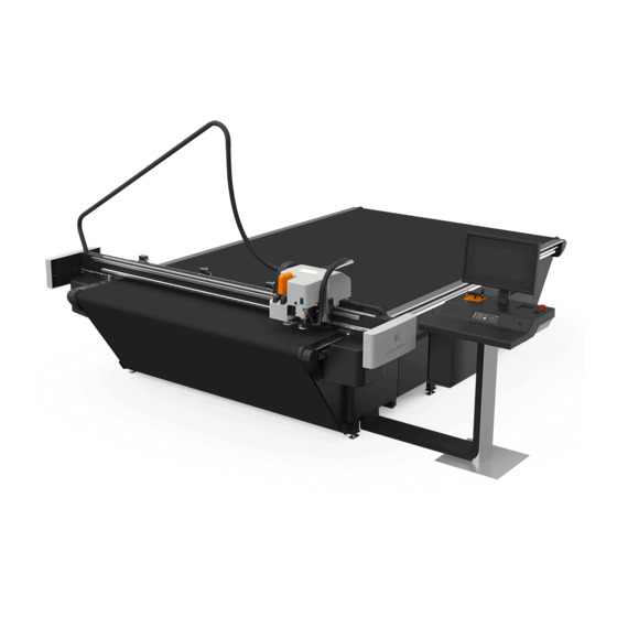
- Page 1 Kongsberg X-series User Manual 09 - 2020 | X-series...
-
Page 2: Table Of Contents
Kongsberg X-series Contents 1. Preface................................9 2. Change Record............................. 10 3. Introduction..............................12 3.1. Welcome.............................. 12 3.2. FCC conformity statement........................13 4. Using this manual............................14 4.1. Main Sections............................14 4.2. Name Styles and Symbols........................15 4.3. Pictures and Illustrations........................15 4.4. Local Languages..........................16 5. - Page 3 Contents 5.11. Residual risks............................. 29 6. System Description............................. 32 6.1. Naming conventions..........................32 6.2. Main Power Switch..........................33 6.3. Operators Panel..........................33 6.4. Variable Blow Back..........................35 6.5. Pressurized Air system........................36 6.6. Application programs available......................37 7. Basic Operations............................38 7.1. Power On Sequence..........................38 7.2.
- Page 4 Kongsberg X-series 10.5. Set Main Reference Point........................58 10.6. Map Table Top Surface........................58 10.7. Reference Points and Coordinate System..................59 10.8. Table Speed............................61 10.9. Table Acceleration..........................61 10.10. Jog Settings............................. 61 10.11. Set Table Top Reference........................62 10.12. Milling Unit Setup..........................63 10.13.
- Page 5 Contents 12.8.9. Chuck Change and Cleaning....................107 12.8.10. Bit Slipping, Chuck Change....................111 12.8.11. Bit Length and Position......................111 12.8.12. False Air valve........................112 12.8.13. Tool Adjustment........................112 12.8.14. Table Top and Height Adjustment..................113 12.8.15. Miscellaneous........................114 12.8.16. LubriCool (MultiCUT-HP only)....................114 12.9. Chiller no 1 (blue top) for MultiCUT-HP....................119 12.9.1.
- Page 6 Kongsberg X-series 13.10.3. Tool adjustment........................144 13.11. KissCut............................145 13.12. MicroCut............................147 13.13. Psaligraphy Knife..........................149 13.13.1. Tool adjustment........................149 13.14. RBI 90-16 (Rigid Board Insert)......................150 13.15. Reciprocating Knife......................... 151 13.15.1. Tool adjustment........................152 13.16. Rigid Material Knife......................... 153 13.17. RotaCut............................154 13.18.
- Page 7 Contents 16. Roll Feeder..............................181 17. Collector Basket............................182 18. TakeUp Unit............................... 183 18.1. Introduction............................183 18.2. Machine Description........................184 18.3. Safety............................... 185 18.4. Features and components........................187 18.5. General operation..........................188 18.6. Applying Winding Material........................ 189 18.7. Start the TakeUp Unit........................190 18.8.
- Page 8 Kongsberg X-series 21. Vacuum Cleaner............................233 21.1. Vacuum Cleaner, Zefiro........................233 21.1.1. How to use..........................233 21.2. Vacuum Cleaner, High-capacity, TB ESKO..................235 21.2.1. How to use..........................235 21.3. Compact Vacuum Cleaner....................... 238 21.3.1. How to use..........................238 22. Install Software............................240 23.
-
Page 9: Preface
This copyright does not indicate that this work has been published. This material, information and instructions for use contained herein are the property of Esko-Graphics Kongsberg AS. There are no warranties granted or extended by this document. Furthermore, Esko-Graphics Kongsberg AS does not warrant, guarantee or make any representations regarding the use, or the results of the use of the system or the information contained herein. -
Page 10: Change Record
Kongsberg X-series 2. Change Record Description Date dd-mm-yy 20-05-2016 jhbe Document is updated according to iPC ver 2.0 06-09-2016 jhbe The importance of MultiCUT chuck cleaning is emphasized 07-10-2016 jhbe Information about LubriCool added 18-10-2016 jhbe CorruSpeed information updated 24-10-2016 jhbe MultiCUT-HP, new chiller and information about old chiller added... - Page 11 Kongsberg X-series Description Date dd-mm-yy 14.11.2019 Bit length and position updated. 20.02.2020 Safety sections + misc. updated 06.03.2020 Updated for Chiller 2020 03.04.2020 Safety sections updated 08.06.2020 FCC conformity statement added 14.09.2020 Minor update 23.09.2020 Safety Regulations updated...
-
Page 12: Introduction
Kongsberg X-series 3. Introduction 3.1. Welcome Welcome to the User Manual for Kongsberg X-series running iPC 2.0. This manual will provide a complete and detailed description of Cutting Table functions. There is a separate user manual for i-cut Production Console (iPC). Thus, actual GUI functions will be referenced in this manual, but the complete and comprehensive description is available in the User Manual for i-cut Production Console. -
Page 13: Fcc Conformity Statement
Kongsberg X-series X44 with Conveyor Belt and MultiCUT-HP 3.2. FCC conformity statement This machine complies with CFR 47 part 15 of the FCC Rules. Operation is subject to the following two conditions: 1. This device may not cause harmful interference 2. -
Page 14: Using This Manual
Kongsberg X-series 4. Using this manual 4.1. Main Sections The manual is divided into the following Main Sections: Safety Regulations • All safety related issues are discussed. System Description • This chapter provides basic knowledge about the machine. Basic Operations •... -
Page 15: Name Styles And Symbols
Kongsberg X-series • Vacuum Cleaner - basic information. • - Frequently Asked Questions 4.2. Name Styles and Symbols Name or style Description Pop-up dialog This is the dialog that appears when you click the Right mouse button. Start button The italic style indicates this is a button on the Operator panel. -
Page 16: Local Languages
Kongsberg X-series 4.4. Local Languages This manual is available in a wide range of local languages. Screen pictures and illustrations remains in English language. -
Page 17: Safety Regulations
Kongsberg X-series 5. Safety Regulations 5.1. Introduction Dangers are designed away as far as practically possible. Nevertheless, all hazards could not be removed. This section must be read carefully to understand the remaining risks, warning symbols, responsibilities, requirements and safety precautions. In particular, operating the table can involve hazards if: •... -
Page 18: The Operators
Have read and understood the instructions described in safety regulation as well as any other safety warnings. Training will be given to operator(s) nominated by the customer by the Esko service engineer as part of the system installation. The training covers: •... -
Page 19: Definition Of Use
• Damage to the system. • Incorrect functionality. • Damage to work materials. Note: Esko is not liable for any damage resulting from such non-intended use. 5.5. Warning sign explanation High voltage warnings • Main Power Unit (MPU) External components are not disconnected by the mains connection of the cutting table. - Page 20 Kongsberg X-series The vacuum pump is not disconnected by the mains connection of the cutting table. Do not remove the cover of this unit until the mains connection has been removed from the socket outlet for the vacuum pump. Note: Different instruction for Cxx and Xxx. •...
- Page 21 Kongsberg X-series EN 60825-1: 1991+A11:1996 CLASS II LASER PRODUCT AVOID EXPOSURE Laser radiation emitted from this aperture General warning Milling tools Milling tools require skill, and must be run by QUALIFIED OPERATORS ONLY This is based on • Safety issues •...
-
Page 22: Attention Areas
Kongsberg X-series These areas are: • Between Y carriage and rack • Between the table top and the moving traverse. • Underneath the tool head. Hearing Protection The Hearing Protection symbol indicates areas where the use of hearing protection is compulsory. Eye Protection The Eye Protection symbol indicates areas where the use of eye protection is compulsory. -
Page 23: High Voltage, Laser Radiation And Moving Parts
Kongsberg X-series Note: A lockable on/off switch on the power line may be required by local regulations, but is part of the site preparation, site owner’ s responsibility, not included in the Kongsberg system delivery unless agreed. 5.6.2. High voltage, laser radiation and moving parts 5.6.3. -
Page 24: Ejection Of Parts When Milling
Kongsberg X-series 5.6.5. Ejection of parts when milling Eye protection must always be used to prevent injury from potential risk of breaking milling bits or pieces of processed material. See also Safety issues on page 95 in the section for milling. 5.6.6. -
Page 25: Safety Devices
Kongsberg X-series 5.7. Safety devices 5.7.1. Overview Main power switch Emergency stop button Warning lamp/status lamp (Y carriage) / milling spindle running (milling unit) DynaGuard safety system Traverse stop switches, DynaGuard safety system Yellow/black tape on the floor to indicate attention area 5.7.2. -
Page 26: Yellow/Black Tape
Kongsberg X-series - Emergency stop active. Servo power to the machine is switched off Note: Activating the emergency stop button does not provide a guarantee against injury. Due to the high kinetic energy of moving parts, do not underestimate stopping distances of traverse, Y carriage and tool head. -
Page 27: Milling Warning Lamp
Kongsberg X-series The DynaGuard Safety System consists of two light beams in front of the traverse and one behind. In addition, there is a stop mechanism mounted on each end of the traverse. Machine movement will stop and Servo Power will be switched off if: •... -
Page 28: Procedures In Case Of Malfunctions
Kongsberg X-series For the operators, Esko recommends the following protective equipment: Close-fitting clothes to avoid being caught by the beam or the tool head which can cause injuries. Gloves to protect against cuts from materials with sharp edges. Eye protection must be used by any personnel working with milling. -
Page 29: Residual Risks
Kongsberg X-series • Emergency buttons unobstructed • Operator has proper training 5.11. Residual risks Despite all safety protection means incorporated in this machine, there are some residual safety risks to be aware of: Beneath traverse end The lower part of the traverse end is un-protected. Actions: •... - Page 30 Kongsberg X-series Rear side of traverse DynaGuard safety system light beams will emergency-stop all machine motions as fast as possible when interrupted by a body part or other object. When the feeder bar or feeder paws (illustration) are mounted, the distance between the rear beam and the mechanics is reduced Actions: •...
- Page 31 Kongsberg X-series Stop time of the milling spindle is up to 4 seconds. This is sucient time to access and touch the milling bit before it has come to a complete stop. It is crucial that the operator always ensures by visual inspection that the milling bit has come to a complete standstill before touching it.
-
Page 32: System Description
Kongsberg X-series 6. System Description 6.1. Naming conventions X-series 1 Table top 6 Main Power on/off switch 2 Y carriage 7 Operator Panel 3 Traverse 8 Emergency Stop button 4 Tools 9 Traverse Safety Stop switches (DynaGuard) 5 Main Power Unit (MPU) 10 Gallows for MultiCUT-HP Axes... -
Page 33: Main Power Switch
Kongsberg X-series X - X-axis X1 - X1 end of traverse Y - Y-axis X2 - X2 end of traverse Z - Z axis The arrows indicates positive moving direction. 6.2. Main Power Switch Switch positions: - the Main Power to the machine is switched OFF. - the Main Power to the machine is switched ON. - Page 34 Kongsberg X-series Press this button to Start Operation. Pause / Safety System Reset Press this button to Pause Operation and Reset Safety System. Vacuum On/Off Press this button to switch Vacuum On/Off. Provides material hold down. Set Panel Reference Point Press this button to set Panel Reference Point.
-
Page 35: Variable Blow Back
Kongsberg X-series Jog speed can be changed from Machine Connection->Machine Configuration->Setup. Incremental Jog Press this button to select Incremental Jog mode. Press the button a second time to disable Incremental Jog mode. Press the two arrows to move Tool Head a large step. Press the single arrow to move Tool Head a small step. -
Page 36: Pressurized Air System
Kongsberg X-series Variable Blow Back - adjust the air flow to a suitable level for the actual material. Use this function to manually enable Blow Back. 6.5. Pressurized Air system General The High Pressure Air System supplies the valves and tooling with compressed air. The compressed air input is connected to a combined Pressure Regulator Valve/Water Trap. -
Page 37: Application Programs Available
Kongsberg X-series The Air Pressure should be adjusted to minimum 6 bar (6 kg/cm2, 6*105 Pa). Recommended pressure level is 7 bar (7 kg/cm2, 7*105 Pa). Where to find Air Pressure Regulator 6.6. Application programs available After installation of iPC, the following application programs are available Control program for the Cutting Table. -
Page 38: Basic Operations
Kongsberg X-series 7. Basic Operations Keep away from Moving Parts during operation. Do not lean on Racks, Guide Ways or Traverse during operation, as this may cause personal injury. Before starting any operation, make sure that: • The Table is free from obstructions •... -
Page 39: Reset Safety System
Kongsberg X-series The Warning Lamp on top of the Y carriage should be constantly lit. Any malfuction of the lamp must be corrected as soon as possible since this is a safety feature. Table Zero Sequence Press Start pushbutton to complete the Table Zero Sequence. The machine will move to the Selected Reference Point. -
Page 40: Continue After Safety Break
Kongsberg X-series To switch off the PC, use the Operating System shutdown procedure.. 7.4. Continue after Safety Break If the Safety System is activated, all movements on the table are stopped and the Warning Lamp starts flashing. To continue operation, proceed as follows: Ensure the table is free from obstructions and ready for operation. -
Page 41: Prepare For A Job
Kongsberg X-series 8. Prepare for a Job 8.1. Introduction Keep away from Moving Parts during operation. Do not lean on Racks, Guide Ways or Traverse during operation, as this may cause personal injury. Before starting any operation, make sure that: •... -
Page 42: Production Setup
Kongsberg X-series 8.4. Production Setup Opened Job->Production Setup. Verify correct Production Setup: • Number of Copies • Accuracy/Speed Prioritization • Select Reference Point and Job Position • Step and Repeat • Registration • Material Handling • Tool Head Parking 8.5. Speed Setting Opened Job->Production Setup->Quality. -
Page 43: Job Execution
Kongsberg X-series From the Vacuum Zone setup – dialog, configure a suitable vacuum area for the job. Select Vacuum Zones that corresponds to the outline of your material. Proper selection is important to achieve the best possible material hold down. 8.8. -
Page 44: Make A Pen Plot
Kongsberg X-series Ensure the vacuum cleaner container is prepared for the actual job. Empty the container regularly. Note: Milling Jobs should be executed in High Quality mode. 8.10. Make a Pen Plot Follow the procedure for how to prepare for and execute a job. Ensure the Ballpoint Pen is clean and ready to use. - Page 45 Kongsberg X-series Measure all tools, started from GUI, procedure Menu Bar->Machine->Adjust Tool Height Machine Panel Toolbar->Tool Height • A wizard dialog appears. • Follow the instructions in the wizard to complete calibration. Measure all tools, started from Operators panel, procedure •...
- Page 46 Kongsberg X-series Press the Measure Tool button. • • A wizard dialog appears. • Follow the instructions in the wizard to complete calibration. • Height Settings Current setting: The automatically measured height value. • Automatic Measurement Adjustment New offset setting: Use this value to modify the height measured by the Measuring Pad.
- Page 47 Kongsberg X-series How to cancel measuring or calibration All Measuring Pad operations are cancelled by: Press Close in the active dialog. • • Press Pause on Operators Panel...
-
Page 48: How To Procedures, Advanced
Kongsberg X-series 9. How To Procedures, Advanced 9.1. Cutting Thick Materials When preparing materials with thickness between 45 – 50 mm (1¾ - 2 in.), the following rules apply: • No Camera operations are available. • Disable Measure Material Thickness. Disable the Depth Referenced from Top function. -
Page 49: Multi Pass Milling
Kongsberg X-series 9.3. Multi Pass Milling Opened Job->Layers->Edit Layer Menu Bar->Layer->Edit Layer 1. pass 2. pass 3. pass - mill through and clean the path Multi Pass Milling is beneficial if you want to mill through a material where the thickness is bigger than the milling bit diameter. -
Page 50: Reverse Operation By Left And Right Rulers
Kongsberg X-series Example below shows configuration of Reverse Operation from Menu Bar->Advanced->Configure Tools Reverse Operation can also be controlled from a button in Layers Tab: Status 1: Selected tool does not currently allow reverse side operation. Can be configured in Configure Tools dialog. -
Page 51: Reverse Operation By Use Of Camera
Kongsberg X-series Workflow Step 1 - the sheet is aligned towards the Step 2 - the sheet flipped and aligned towards the Left Ruler. Right Ruler. The rest of the Job is completed. Reverse Operations are completed. A typical use of Reverse Operation is when you want to add a Crease line on the front side of a material that you normally prepare from the rear side. -
Page 52: Reverse Operation In Combination With Step And Repeat
Kongsberg X-series A current limitation of Reverse Operation with Camera is that all layers (except the regmark layer) must be processed from the reverse side. The function requires that the table is equipped with a Tool Head with Camera, and that the job has Regmarks. -
Page 53: Multizone Production
Kongsberg X-series 9.6. MultiZone Production Introduction In User Manual for i-cut Production Console, general information about MultiZone Production is available. In this chapter, more machine-specific issues are described. MZP Panel Each work zone is equipped with a panel that makes it possible to run the complete MultiZone Production sequence from the table. -
Page 54: Multizone, Workflow
Kongsberg X-series MultiZones The illustration shows the most actual zones available for MultiZone Production Limitations The last section of a multizone table is somewhat smaller than the first one(s). As a consequence, the work area available for MultiZone Production is determined by the size of the last section. - Page 55 Kongsberg X-series - Recommended material flow direction. - Attention Area. During operation in one zone, parts of the traverse will move into the other zone (photo cell beams, traverse end cover). To ensure a continous workflow, the operator should be very careful inside the Attention Area, not to trigger the safety system by his body or by material in and out.
-
Page 56: System Setup
Kongsberg X-series 10. System Setup 10.1. Introduction This chapter will explain functions and parameters that are important for the X-system to run properly. It is a supplement to the information available from the User Manual for i-cut Production Console. Examine each step carefully to ensure proper settings: One time adjustments completed at the factory The functions are included here as a reference. -
Page 57: Adjust X1 To X2 Angle
Kongsberg X-series Set Table Top Reference Conveyor Belt Control Board Size 10.2. Adjust X1 to X2 Angle Machine Connection->Machine Configuration->Installation_>Adjust X1 to X2 Angle Use this wizard to obtain correct angle between X axis and Y axis. Typical use is after maintenance or repair. Procedure: 1. -
Page 58: Set Ruler Position
Kongsberg X-series 10.4. Set Ruler Position Machine Connection->Machine Configuration->Installation_>Set Ruler Position Follow instructions from the wizard. If your table is equipped with Rulers, please complete the wizard for left and right ruler. For the table to operate properly an exact registration of the Ruler Positions is necessary. This is a one time job, but it can be necessary to repeat the procedure if mechanical maintenance has been carried out on the table or traverse. -
Page 59: Reference Points And Coordinate System
Kongsberg X-series Note: iPC 2.1: The mechanism of compensating Z height during cutting, based on table top mapping, has been disabled when cutting underlay has been measured to be more than 5mm. This level is normally reached when milling on top of milling mat and conveyor belt. This exception was introduced long time ago, before using conveyor belts. - Page 60 Kongsberg X-series Using the Main Reference Point during program execution ensures correct operation. User Defined Reference Points You can specify User Defined Reference Points. User Defined Reference Points are used if you want your job positioned in a fixed position on the table (Rx), but not in the Main Reference Point (R).
-
Page 61: Jog Settings
Kongsberg X-series When you use the Right Ruler, the Reference Point will automatically be moved to an identical distance from the Right Ruler, as it is defined from the Left Ruler. The Right Ruler is normally used for Reverse Score operations. At the same time the direction of the X axis is reversed. -
Page 62: Set Table Top Reference
Kongsberg X-series Machine Connection->Machine Configuration->Setup_>Jog Speed Specify low and high Jog Speed Incremental Jog Step Size The size of the Incremental Jog movements can be customized. Machine Connection->Machine Configuration->Setup_>Incremental Jog Specify Step Size to be used. Jog Directions Machine Connection->Machine Configuration->Setup_>Jog Panel Direction Use this function to align the Jog Directions with the orientation of the Operator Station. -
Page 63: Milling Unit Setup
Kongsberg X-series 5. In the wizard, press OK to start measurement. 10.12. Milling Unit Setup Machine Connection->Machine Configuration->HW Configuration->Milling Unit setup From the Milling Unit setup dialog, maintain the following parameters: Specify Milling unit If a milling unit is mounded, spedify milling unit type. If no milling unit is mounted, select None. -
Page 64: Tool Configuration And Adjustment
Kongsberg X-series 11. Tool Configuration and Adjustment 11.1. Introduction Machine Connection->Tool Configuration The Tool Configuration dialog is used for all tool settings and adjustments. 11.2. Adjust Active Tool From the Adjust Selected Tool – dialog, all Tool Adjustment Wizards are executed. The following procedures are general descriptions of how to adjust the tools. -
Page 65: Tool Height Calibration
Kongsberg X-series See the description of each Tool Type for more specific information: We recommend using a sheet of Folding Carton material, 5-6 mm / 0.2 inch, when executing the adjustments. Note: All tools need to be adjusted in the position they will be used. Before any adjustment, complete a Table Top Reference function: Menu Bar->Machine->Set Table Top Reference Machine Panel Toolbar->Table Top Reference... - Page 66 Kongsberg X-series Lag Setting Lag – lag value. This is the distance from the rotation center to the back of the Knife Blade. Enter the value as measured or as found using the Lag test, see below. Width – knife bottom width Enter the measured knife bottom width.
-
Page 67: Rotation Adjustment (For Rotating Tools)
Kongsberg X-series Circle Lag Circle quality is determined by a parameter called Circle Lag. The parameter value will vary depending upon the actual material. Therefore, the adjustment is located in the Job Setup dialog. 11.5. Rotation Adjustment (for Rotating tools) Optimal Angular Offset may vary with different material strength and thickness. -
Page 68: Center Offset Adjustment
Kongsberg X-series 10. Note how the knife enters into the material. 11. Press Tool Override Down once more to lift the Tool again. 12. If knife enters exact into the cut, the angle is correct; select Finish to exit. 13. If seen in the cutting direction, the knife enters to the left of the cut, the Angular Offset Value should be decreased. -
Page 69: Manual Adjustment Of Center Offset And Angle
Kongsberg X-series 11. Press Tool Override Down once more to lift the Tool. 12. The two cuts should follow exactly the same path. 13. If exact, the Center Offset is correct, select Finish to exit. 14. If not, modify the Center Offset Value and repeat from point 6. 11.7. -
Page 70: Maintain Tool List (More
Kongsberg X-series The Laser Pointer is the reference: 1. Place an appropriate test material on the table, and switch Vacuum On. 2. Select the Tool to be adjusted. 3. Press Adjust Active Tool to enter the Wizard Selection Dialog. 4. Select Offset Adjustment. 5. - Page 71 Kongsberg X-series • Add new Tools • Add tools that fails during Automatic Tool Detection The Tool is added to the Tool List.
-
Page 72: Tooling System
Kongsberg X-series 12. Tooling System Knife Blades and Milling bits are extremely sharp. Take care when handling Knife Tools and Milling bits. Laser Radiation. Do not stare into beam! The tool head is equipped with a class II laser pointer. Emitted laser power < 1 mW. 12.1. -
Page 73: Tool Heads Available, Overview
Kongsberg X-series Motor cable and connector When disconnecting the motor cable, use the plug. 12.3. Tool Heads available, overview FlexiHead FlexiHead is a Multi-purpose Tool Head prepared for the following tools: Bevel Knife KissCut Knife Psaligraphy Knife Crease Tool Knife Tool Reciprocating Knife CorruSpeed Knife Tool MicroCut... -
Page 74: Tool Head Mount / Dismount
Kongsberg X-series MultiCut-HP MultiCUT-HP is a special purpose tool head, which can be equipped as follows: • Two general tool positions prepared for the standard FlexiHead tools. • Milling tool equipped with a high speed milling spindle. 12.4. Tool Head mount / dismount >>... - Page 75 Kongsberg X-series Tool Head Description 1. Tool positions 1, 2, 3 with locking knobs 2. Outlet for Reciprocating Knife motor 3. Laser pointer 4. Measuring foot / material hold down foot. Has 3 functions: a. Measure the thickness of the material on the table b.
-
Page 76: Powerhead
Kongsberg X-series Tool Rotation Adjust tool angle tangential to moving direction Center Offset Adjust tool sideways until centered Tool Offset Adjust offset to Laser Pointer. 12.6. PowerHead Tool Head Description 1. Tool position 1 (FlexiHead tool insert) 2. Tool position 2 (FlexiHead tool insert) 3. -
Page 77: Ø150 Mm Crease Wheel
Kongsberg X-series Lag Setting The lag value depends upon the blade adapter. Nominal value is 0 mm. Tool Rotation Adjust tool angle tangential to moving direction Center Offset Adjust tool sideways until centered Tool Offset Adjust offset to Laser Pointer. For more information about how to run the adjustment wizards, see Tool Configuration. -
Page 78: Crease Adapter Ø26 Mm
Kongsberg X-series 12.6.2. Crease Adapter ø26 mm The Crease Adapter allows 26 mm (1 in.) crease wheels to be used in the Heavy Duty crease tool position. The tool is adjusted and operates as an ordinary crease tool. 12.6.3. Perforation Wheel ø60 mm Use Perforation Wheel to prepare perforation lines at high speed. - Page 79 Kongsberg X-series Perforation Wheel assembly Parts in assembly Ensure the path is clean. Fix cover properly. Push / pull the perforation wheel in / out from the adapter.
-
Page 80: Hd Knife Tool
Kongsberg X-series Tool Adjustment For this tool, complete the following adjustments: Adjustment Description Tool Height Measured automatically, possible to add an Offset Value. Lag Setting The Lag value depends upon the Blade Adapter. Nominal value is 0 mm. Tool Rotation Adjust Tool Angle tangential to Moving Direction. -
Page 81: V-Notch Knife
Kongsberg X-series 12.6.5. V-notch Knife V-notch Knife mounted on a Heavy-Duty Unit. How to insert / remove V-notch Knife Turn the V-notch Knife (A) correctly to fit the Both latch pins are used for the V-notch Knife. alignment pin (B). - Page 82 Kongsberg X-series How to replace a Knife Blade This picture shows how the Knife Blade is aligned 1. Loosen the two screws (2) of the Knife Blade using two guide pins beneath the blade clamping. clamping. 2. Carefully remove the blade (1). 3.
- Page 83 Kongsberg X-series Center Offset Adjust tool sideways until centered Tool Offset Adjust offset to laser pointer Tool Configuration. For more information about how to run the adjustment wizards, see V-notch Knife settings are maintained from: Opened Job->Layers->Edit Layer Menu Bar->Layer->Edit Layer How to set the depth of the V-notch Knife 1.
- Page 84 Kongsberg X-series Different angles A wide range of V-notch knives is available, providing different knife angles, v: 15 , 22.5 , 30 , 45 , 47.5 V-notch knife tools, modes of operation Opened Job > Layers Tab > Edit Layer Menu Bar->Layer->Edit Layer...
- Page 85 Kongsberg X-series V-notch specific parameters Rotational compensation Rotational compensation is used to optimize V-notch / Bevel Cut quality in challenging materials and use cases. This feature will pre-load the knife blade and overcome mechanical flexibility in the system. Notch angle Notch Angle is used for the VariAngle unit *) only, and determines the angle of the blade into the is a vertical cut.
- Page 86 Kongsberg X-series Waste Cut Waste Cut adds a third cut line to ease removal of waste Geometry When the knife angle is 45 and you cut through the material, the width of the cut is W = 2 x h. Folding If you prepare a material for folding, the following rules applies: •...
-
Page 87: Bevel Knife 45
Kongsberg X-series This illustration shows a typical use of Triple Cut Function. The middle wall is not cut by (2) or (3), making the material impossible to fold. The Triple Cut Function (1) cut the middle wall and you can fold the material nicely. Adjustment sign and cut direction 12.6.6. - Page 88 Kongsberg X-series Tool Head Description 1. Height sensor 2. Knife adapter 3. Material hold down wheels. Operator protection. 4. Laser pointer Tool Adjustments, FoamHead Tool Height Correct tool height relative to table top Lag Setting Default lag value for the long foam knife is 4.5mm/0,18" Tool Rotation Adjust tool angle tangential to moving direction Center Offset...
- Page 89 Kongsberg X-series Partial through cut Partial through cut is specified as an absolute value or a percentage value in the Job Setup dialogue. Please note that the value is specified from the top of the material and down. Cutting quality To obtain best quality when cutting details, as small circles, we recommend: •...
-
Page 90: Multicut/Multicut-Hp
Kongsberg X-series Disable Material Thickness Measurement Opened Job->Production Setup->Material Handling For the Foam Knife Tool, the Disable Material Thickness Measurement function is available. Use this function if • Your foam material is too soft for the measuring system. • The surface of your material is un-even. When the Disable Material Thickness Measurement function is enabled, the following rules applies: •... - Page 91 Tool change Pneumatic Pneumatic Chucks Different chucks are available from http://www.esko.com/en/store/kongsberg-bits-blades/ Be aware that the chucks for HF-45 (MultiCUT) and HF-62 (MultiCUT-HP) are different and they cannot interchange. Replacing a chuck Replacing a chuck is described in detail in Chuck Change and Cleaning on page 107.
-
Page 92: Tool Head Description
Kongsberg X-series 12.8.2. Tool Head description Tool Head Description MultiCUT-HP 1. Tool position 1 (FlexiHead tool insert) 2. Tool position 2 (FlexiHead tool insert) 3. Laser pointer 4. Tool position 3 5. Measuring foot / material hold down foot 6. - Page 93 Kongsberg X-series 2. Air Blow adjustment. Air blow is used for milling bit cooling and to ease chip removal. Adjust for proper operation. 3. Warning Lamp for spindle running. 4. Chuck Open/Close. The shown position is closed. Note: Never close the chuck empty. This can cause damage to the chuck. If the milling bit is removed, close the chuck on a dummy bit.
- Page 94 Kongsberg X-series Release water tubes: Pull down the release locker on each connector. The suction tube is fixed to the suction house. When the milling tool is not in use, the tubes are fixed to the gallows as shown here. Chiller / MultiCUT-HP start up time Depending upon the environmental temperature, the Chiller needs some start-up time after Power On before it is ready to operate.
-
Page 95: Cooling Water Connections
Kongsberg X-series Suction house, adjustable height On MultiCUT-HP, you can lock the suction house in any height; still, it is allowed to move upwards. This function is useful in order to 1. Adapt to different material thicknesses. 2. Allow false air input in order to reduce suction force. Procedure: 1. - Page 96 Kongsberg X-series Depending upon the material processed, milling introduces some risks. It is a good rule to keep an eye on a milling job being executed. Pay special attention to: • Do not leave the machine running if the vacuum cleaner can be over-filled. This might cause damage, or in worst case a fire if the suction house is clogged.
- Page 97 Kongsberg X-series Hearing protection The noise generated by milling varies with the material being processed and running parameters. Hearing protection is highly recommended and may even be mandatory. Spindle speed Never use speeds higher than recommended by the bit supplier. Special care should be taken when using bits with cutting diameter larger than shank diameter.
-
Page 98: Precautions
Kongsberg X-series 12.8.5. Precautions Follow these precautions to take care of the milling spindle, which is a high precision unit, that can get damaged by careless use. Supervision of the milling spindle power Machine Panel->Spindle Power The MultiCUT-HP spindle is prepared for continuous operation between 0 – 100 % Watt. A power load of 70-80% will allow good working conditions for the Spindle Motor. - Page 99 Kongsberg X-series Chuck Open/Close valve operation Never operate the Chuck Open/Close valve while the spindle is running. This will destroy the spindle. Air Pressure and Quality Never run IBAG spindle with Pressurized Air disconnected. This may destroy the spindle. Keep this in mind also for test purposes.
- Page 100 Kongsberg X-series Long term storage More than 4 weeks storage of a spindle or a MultiCUT/MultiCUT-HP requires: 1. Turn the spindle by hand about 20 turn every 4 weeks. 2. Spindle must be stored horizontally. Consider having a replacement spindle If MultiCUT-HP is used in regular production, it is recommended to have a Replacement Spindle.
-
Page 101: Milling Advice
Kongsberg X-series 12.8.6. Milling advice Follow this advice for obtaining the best possible milling results. Milling bits For thin materials, use bits with short cutting length. For best performance and minimum wear, do not let the bit stick out more than necessary . - Page 102 Kongsberg X-series Never use higher RPM than recommended by the bit supplier. Special care should be taken when using bits with cutting diameter larger than shank diameter. Bits with small cutting diameter (3-4 mm; 0.12-0.16 in) are more balanced than bits with larger cutting diameter Thus, they can run with higher RPM, normally 60.000.
- Page 103 Kongsberg X-series Acrylic or Multi Purpose bits 1. Acrylic Bits (A) are polished, extra sharp for acrylic, wood etc. 2. Multi Purpose Bits (MP) have a higher wear resistance, and are suitable for aluface, plastics, MDF, plywood, wood etc. Multi Purpose Bits can be identified by a small tooth at the tip (left hand bit on the picture).
-
Page 104: Cleaner Device
Kongsberg X-series 2. Cover unused table area to increase Vacuum Hold Down Level. 3. Use Wash-Out functions instead of creating small waste parts. Using other tools in combination with the MultiCUT-HP It might be necessary to reduce the acceleration in order to achieve an optimal Cutting Quality when combining a heavy tool head with high quality cutting tools. - Page 105 Kongsberg X-series Lock the house in its up position. Observe that the milling bit is not rotating. Use a cloth to hold the bit. Move the Chuck Open/Close lever down to open the Chuck. Put the bit in a proper storage container. Insert a new milling bit.
- Page 106 Kongsberg X-series Regularly, perform a Chuck cleaning, following the dedicated procedure; Chuck Change and Cleaning on page 107. Note: Never use Compressed Air for cleaning. Using Sleeve Adjustment Tool 34054510 ADJUSTMENT SLEEVE MULTICUT 20 34038406 ADJUSTMENT SLEEVE MULTICUT 28 Sleeve Adjustment Tools are available in two versions, with different depths.
-
Page 107: Chuck Change And Cleaning
Kongsberg X-series If a bit is stuck If a Milling Bit is stuck in the chuck, the probable cause is low air pressure. To release a Milling Bit from the chuck, a pressure of 7 bar is required. If necessary, check the Pressurized Air Regulator Valve, or the Pressurized Air source. If the bit is still stuck, see the Chuck Change and Cleaning on page 107 section about how to unscrew... - Page 108 Kongsberg X-series Place the Tool Head on the table. Open the chuck and remove any bit. Note: Never apply Compressed Air for cleaning. Apply the 17 mm key to hold the Spindle Rotor. Note: Do not turn the rotor when Chuck is in open position.
- Page 109 Kongsberg X-series If the bit is stuck, hold the rotor with the 17 mm key and unscrew with a 12 mm key. Note: Tool Open must be pressurized. Use the Taper Brush to clean the Taper. Push the Air Clean Button to help remove contamination.
- Page 110 Torque up the chuck by hand, using the Chuck Tool with a Dummy Bit. Hold the rotor with the 17 mm key. Close the chuck on a Dummy Bit. Chuck Maintenance Kits are available in the Esko Store on www.esko.com.
-
Page 111: Bit Slipping, Chuck Change
2. Bit vibrations. When replacing the chuck, follow instructions in Chuck Change and Clean. New chucks are available from Esko store. 12.8.11. Bit Length and Position Keep distance d small. For best performance and minimum wear, do not let the bit stick out more than necessary. -
Page 112: False Air Valve
Kongsberg X-series Balanced Bits Bits with balanced surface should have a clamping length f of min. 20 mm/0.8 inches. Maximum balancing length g is 12 mm/0.5 inches. 12.8.12. False Air valve MultiCUT is equipped with a False Air Valve. When milling small parts, use the False Air Valve to reduce the suction force. 12.8.13. - Page 113 Kongsberg X-series 12.8.14. Table Top and Height Adjustment The following rules apply when adjusting MultiCUT/MultiCUT-HP T = Cutting table, C = Cutting underlay Map Table Top function is carried out on top of the Cutting underlay. U = Milling underlay The Table Top Reference function is carried out on top of the Milling underlay ...
-
Page 114: Miscellaneous
Kongsberg X-series 12.8.15. Miscellaneous Warm Up Machine Panel Toolbar->Warm Up To protect the Spindle, mandatory Warm Up is implemented. If the Spindle has been inactive for 8 hours or more, a 3 min. Warm Up is required. If the Spindle has been inactive for 4 weeks or more, an extended sequence is required, called Run In. This takes 20 minutes. - Page 115 Kongsberg X-series Introduction LubriCool mounted on MultiCUT-HP. • A - inspection window. • B - Suction cup with nozzles. LubriCool control unit How to use...
- Page 116 Kongsberg X-series LubriCool is on when the Vacuum Cleaner is on. For materials where lubrication is not suitable, use the ON/OFF switch on the LubriCool Control Unit to switch off lubrication. Inspection Opening When the LubriCool unit is on, you can see light in the control relays inside the unit.
- Page 117 Kongsberg X-series Nozzle Unit Suction Ring MultiCUT-HP is delivered with one Nozzle Unit for the LubriCool function and one Suction Ring with just a brush, and with bigger suction opening. Use the Nozzle Unit when the LubriCool function is beneficial only! •...
- Page 118 Kongsberg X-series Remove / insert the Nozzle Unit oil tube from the Nozzle Unit with oil tube outlet. Cleaning Proper cleaning is crucial for correct operation. • Release locker A and remove the nozzle unit. • Use vacuum cleaner to clean MultiCUT-HP suction house.
-
Page 119: Chiller No 1 (Blue Top) For Multicut-Hp
Kongsberg X-series 12.9. Chiller no 1 (blue top) for MultiCUT-HP 12.9.1. Introduction This is chiller 1, replaced in October 2016 by a new model named chiller2016. Flow Measurement During operation, check the water flow level displayed on the chiller meter. For proper operation, the flow level should be >... -
Page 120: Chiller, Error Conditions
Kongsberg X-series 12.9.2. Chiller, Error Conditions One common error signal is routed from the Chiller system to the inverter and further into the control system. The following error conditions are monitored: • Temperature out of range (high and low) • Liquid flow too low (less than 0.5 l/min). - Page 121 Kongsberg X-series Press On/Off button to start the heater. The letters BCS are displayed. To turn unit off, push and hold the button for 3 seconds. Media temperature is displayed. Green light on - the unit is on, and the specified temperature is reached. Green light flashing - heating elements are operating.
-
Page 122: Chiller 2016 / Chiller 2020 For Multicut-Hp
Kongsberg X-series Program Temperature range Temperature range to Hysteresis from ( Factory Setting Correct factory setting is Program = 5 and temperature = 26 oC (Chiller with heater). 12.10. Chiller 2016 / Chiller 2020 for MultiCUT-HP 12.10.1. Introduction Chiller 2016 and Chiller 2020 refers to two similar models introduced those years. Chiller 2020 differs from previous models by being a heat exchanger, which will not be able to lower the temperature below ambient. -
Page 123: Startup
Kongsberg X-series 12.10.2. Startup Ensure the following pre-requisites are in place for correct startup: • Note: Never start the chiller without liquid. • Signal cable (to inverter) is connected to the chiller unit. • Chiller fluid level should be MAX. If not, fill with fresh water. •... -
Page 124: Measuring Foot
Kongsberg X-series During normal operation, the cooling medium temperature is displayed. If any chiller failure occurs: • Alarm signal is generated. • Chiller will stop. • Look at the chiller display to see the real reason for the problem: Code Description Water level or water flow too low. -
Page 125: Laser Pointer
Kongsberg X-series Note: In Q1/2017, the strong springs used earlier were replaced by a set of softer springs, in order to avoid the foot scratching the material surface. If needed, a set of strong springs, together with a replacement procedure, is available in the tool kit included in the shipment. -
Page 126: X-Pad
Kongsberg X-series 12.13. X-Pad 12.13.1. X-Pad Calibration Note: Remove any cup or cover surrounding the tool tip during this procedure. As a consequence, take care. In order to work properly, the X-Pad itself must be calibrated. The following tools are applicable when the calibration procedure is carried out: •... -
Page 127: Tool Depth And X-Pad
Kongsberg X-series • Pause button light is off. 12.13.2. Tool Depth and X-Pad Be aware how X-Pad is working; it is the tool tip that is measured. Depending upon the actual tool, it might be necessary to add depth in order to achieve cut or drill hole through the material. -
Page 128: Tool Inserts
Kongsberg X-series 13. Tool inserts Knife Blades are extremely sharp. Take care when handling Knife Tools. 13.1. Ball Point Pen The Ball Point Pen tool is available for pen drawing. Tool pressure is adjustable by a knob on top of the tool. -
Page 129: Bevel Knife
Kongsberg X-series Parameter Description Tool Height The tool tip should touch the material surface. Center Offset Adjust tool sideways until centered. Tool Offset Adjust offset relative to laser pointer. For more information about how to run the adjustment wizards, see Tool Configuration. -
Page 130: Bevel Knife U20
Kongsberg X-series About tool adjustment For the Bevel Knife, we recommend the manual procedures for tool rotation and centre offset adjustment. Use a thin Folding Carton material when adjusting tool rotation and centre offset. Remember that you should look at the bottom side of the material for correct alignment. The adjustments depend upon the actual material due to weight, structure and thickness. - Page 131 Kongsberg X-series 1. Keep the tool in upright position during this process. 2. Remove the cap and the plunger. 3. Pour spheres into the tool. 4. Insert the plunger and the cap. Shake the tool lightly. 5. Push the dispensing mechanism up. 6.
- Page 132 Kongsberg X-series The supplied milling bit is heavily unbalanced and should not be run faster than 20.000 RPM to avoid excessive wear to the milling spindle! This also means that you should not use this bit when warming up the milling spindle as the warm up sequence exceeds 20.000rpm.
- Page 133 Kongsberg X-series If the Laser Spot is offset from the sphere, jog the tool head until the Laser Spot is placed exactly on top of the sphere. Click Finish and close the remaining tool adjustment dialogs. Configure Tool Menu Bar->Advanced->Configure Tools... Braille Tool should be defined with the following parameters enabled: •...
- Page 134 Kongsberg X-series Velocity Z Velocity Z is material dependent and may require experimentation. The value shown in the illustration is suitable for (and has been tested with) 3mm Dibond. Z-axis depth Z-axis depth is determined by the material thickness and hole depth. It can be calculated as: Z-axis depth = hole depth –...
-
Page 135: Corruspeed Knife
Kongsberg X-series Drill Holes check box must be enabled for the Braille Tool to work properly. Creating a Braille Job file Braille grade 1 & 2 Grade 1 braille is a letter-by-letter translation of texts. If you wish to create Grade 1 braille signage you can use any available braille font. These fonts may be freely available on the internet. - Page 136 Kongsberg X-series During processing, the corrugated material is partly crushed by the foot. The result is: • You can run at high speed. • The risk for material tear is significantly reduced. Foot pressure adjustment Material crushing depends upon two adjustments: A - Knife tip exposed Adjust until the distance d is 1.0...
-
Page 137: Tool Adjustment
Kongsberg X-series For Knife Blade change, remove the foot. Note: Be extremely careful when mounting the foot. The locking screw will always point towards the cutting direction Observe the alignment pins. After a blade change, the tool depth should be checked again. -
Page 138: Crease Tool
Kongsberg X-series 13.6. Crease Tool Crease Tool The Crease Tool is a multipurpose tool allowing a wide range of creasing wheels. Lag is nominal 0 mm. Replace crease wheel Push the wheel into position 13.6.1. Tool adjustment For this tool, complete the following adjustments: Parameter Description Tool Height... -
Page 139: Crease Tool, 60 Mm
Kongsberg X-series For more information about how to run the adjustment wizards, see Tool Configuration. 13.7. Crease Tool, 60 mm Use the ø60 mm Crease Tool to avoid cracking the liner. Lag is nominal 0 mm. The crease wheel is attached to the tool after it has been mounted in the Tool Head. -
Page 140: Drill Tools
Kongsberg X-series Parameter Description Tool Rotation Adjust tool angle tangential to moving direction. Center Offset Adjust tool sideways until centered. Tool Offset Adjust offset relative to Laser Pointer. For more information about how to run the adjustment wizards, see Tool Configuration. -
Page 141: Reboard Drill Tool
Kongsberg X-series 13.8.2. Reboard Drill Tool Reboard Drill Tool is a tool insert for a standard XL tool position. This drill tool is for use in re-board and other paper - based materials. The tool is prepared for drill bits 0.5 –... -
Page 142: Tool Adjustment
Kongsberg X-series 13.8.4. Tool Adjustment For this tool, complete the following adjustments: Parameter Description Tool Height The tool tip should touch the material surface. Tool Offset Adjust offset relative to laser pointer. For more information about how to run the adjustment wizards, see Tool Configuration. -
Page 143: Ink Tool
Kongsberg X-series Lag adjustments for Foam Knife The lag for the Foam Knife tool should be 2.5mm (0.1") How to replace a Knife Blade Follow instructions for Static Knife. 13.10. Ink Tool Two ink tool models are available; Liquid Ink Tool and Fibertip Tool. Lag is nominal 0 mm. -
Page 144: Fibertip Tool
Kongsberg X-series Ink tool assembly 13.10.2. Fibertip Tool Fibertip Tool is for ink drawing. The tool is prepared for Staedtler Lumocolor insert. Fibertip tool assembly 13.10.3. Tool adjustment For this tool, complete the following adjustments:... -
Page 145: Kisscut
Kongsberg X-series Parameter Description Tool Height The tool tip should touch the material surface. Lag Setting The knife lag depends upon the actual knife blade adapter and knife blade. Tool Rotation Adjust tool angle tangential to moving direction. Center Offset Adjust tool sideways until centered. - Page 146 Kongsberg X-series Replace Knife Blade This figure shows how the Knife Blade is fixed A special hand tool is available as an aid when inside the KissCut knife tool. replacing knives. Use this hand tool when removing and inserting knives into the tool. The friction between the Alignment Pin A and the Knife Blade keeps the blade in place.
-
Page 147: Microcut
Kongsberg X-series Foot solution Normally, the KissCut knife tool is used without the foot mounted. When the foot is mounted, the cutting depth d is controlled by the adjustable screw S. For this tool, complete the following adjustments: Parameter Description Lag Setting The knife lag depends upon the actual knife blade adapter and knife blade. - Page 148 Kongsberg X-series How to set Cutting Depth • When inserting a new Knife Blade, align the tip of the knife with the sliding sleeve and zero the depth meter (A). • Then adjust the micrometer screw (Starret micrometer (218)) until desired depth is displayed (B).
-
Page 149: Psaligraphy Knife
Kongsberg X-series 13.13. Psaligraphy Knife Note: iPC version 2.0 or higher is required to run this tool. Psaligraphy Knife is a tool for cutting of fine details in paper and folding carton. Lag is nominal 0 mm. Replace Knife Blade For Knife Blade change, remove the foot. -
Page 150: Rbi 90-16 (Rigid Board Insert)
Kongsberg X-series Parameter Description Lag Setting The knife lag depends upon the actual knife blade adapter and knife blade. Tool Rotation Adjust tool angle tangential to moving direction. Center Offset Adjust tool sideways until centered. Tool Offset Adjust offset relative to Laser Pointer. For more information about how to run the adjustment wizards, see Tool Configuration. -
Page 151: Reciprocating Knife
Kongsberg X-series Parameter Description Tool Height The tool tip should touch the material surface. Lag Setting Lag = 8.5 mm / 0.33 in. Tool Rotation Adjust tool angle tangential to moving direction. Center Offset Adjust tool sideways until centered. Tool Offset Adjust offset relative to laser pointer. -
Page 152: Tool Adjustment
Kongsberg X-series • The same set of knife adapters can be used. Replace Knife Blade Pull out the electrical connection. Note: Pull using the connector, not just the cable. Remove the foot by pulling the foot straight out. Loosen the screw A and replace the knife. Ensure the knife has correct position relative to the screw. -
Page 153: Rigid Material Knife
Kongsberg X-series Parameter Description Center Offset Adjust tool sideways until centered. Tool Offset Adjust offset relative to Laser Pointer. For more information about how to run the adjustment wizards, see Tool Configuration. 13.16. Rigid Material Knife Insert / remove knife blade Ensure the blade is correctly aligned. -
Page 154: Rotacut
Kongsberg X-series Parameter Description Tool Height The tool tip should touch the material surface. Lag Setting The knife lag depends upon the blade adapter. Nominal value is 0-4 mm. Tool Rotation Adjust tool angle tangential to moving direction. Center Offset Adjust tool sideways until centered. - Page 155 Kongsberg X-series Tool Height Tool Height for RotaCut is manually adjusted using the tool height adjustment wizard available from the Tool Configuration dialog. Follow the instructions in the dialog. Be careful, though, not to adjust the cutting depth too deep into the cutting underlay (figure at left).
- Page 156 Kongsberg X-series Use the spanner and the hexagonal screw driver to Observe the alignment pin in the foot and the fix the blade properly. groove in the tool shaft. Position the foot onto the tool shaft as shown at left. Note: This operation has to be carried out after the tool insert is in place in the tool head.
-
Page 157: Static Knife
Kongsberg X-series Tool Adjustment Use the standard adjustment wizards when adjusting the knife. We recommend using a sheet of corrugated material, 5-6 mm / 0.2 inch, when executing the wizards. Parameter Description Lag Setting See above. Tool Height See above. Tool Rotation Adjust tool angle tangential to moving direction. -
Page 158: Tool Adjustment
Kongsberg X-series After a blade change, the tool depth should be checked again. Knife direction The locking screw will always point towards the The locking screw will always point towards the cutting direction cutting direction 13.18.1. Tool adjustment For this tool, complete the following adjustments: Parameter Description Tool Height... -
Page 159: Vi30-16 Knife Tool
Kongsberg X-series 13.19. VI30-16 Knife Tool A – knife adapter Lag = 0mm. 13.19.1. VIxx Knife Tool, Mounting/Adjustment Remove the knife adapter from the tool and insert Position the tool adapter onto the shaft. the upper part into the tool position. Observe Alignment Pin orientation. - Page 160 Kongsberg X-series …in order to lock the tool adapter in its position. How to set the cutting depth of the VIxx Knife Tool The default cutting depth is to cut through the entire material. Define the depth of the bevel cut in the Layer Setup. Normally, the cut should extend down to just above the bottom liner.
-
Page 161: Vi45 Knife Tool
Kongsberg X-series 13.20. VI45 Knife Tool A – knife adapter Lag = 0mm. 13.20.1. VIxx Knife Tool, Mounting/Adjustment Remove the knife adapter from the tool and insert Position the tool adapter onto the shaft. the upper part into the tool position. Observe Alignment Pin orientation. -
Page 162: Vi45-10/12 Knife Tool
Kongsberg X-series …in order to lock the tool adapter in its position. How to set the cutting depth of the VIxx Knife Tool The default cutting depth is to cut through the entire material. Define the depth of the bevel cut in the Layer Setup. Normally, the cut should extend down to just above the bottom liner. -
Page 163: Vixx Knife Tool, Mounting/Adjustment
Kongsberg X-series 13.21.1. VIxx Knife Tool, Mounting/Adjustment Remove the knife adapter from the tool and insert Position the tool adapter onto the shaft. the upper part into the tool position. Observe Alignment Pin orientation. Keep the knife adapter in this position while you turn the tool shaft…... - Page 164 Kongsberg X-series Normally, the cut should extend down to just above the bottom liner. After a blade change, the tool depth should be checked again. About tool adjustment For the VIxx Knife Tool, we recommend the manual procedures for tool rotation and centre offset adjustment.
-
Page 165: Maintenance
Kongsberg X-series 14. Maintenance More information about maintenance is available in the Maintenance Manual. Warning Main Power should be switched off before cleaning is carried out. 14.1. Daily maintenance • Inspect the equipment in order to prevent any irregularities. • The table surface should be kept clean at all times. -
Page 166: Maintenance, I-Bf Board Feeder
Kongsberg X-series 14.4. Maintenance, i-BF board feeder 14.4.1. About maintenance Daily maintenance 1. Clean machine table surface to remove dust, media remnants, and other debris using a non- abrasive brush or cloth. Do not use solvents. 2. Clean vacuum cups from ink, tape, glue, or contaminants, which may prevent good vacuum adhesion to the board media. -
Page 167: Spare Parts
Kongsberg X-series There is no specific need for a maintenance interval for the TakeUp Unit . It is recommended to check the foam rubber on the Waste Handling kit daily for damage and if it is worn out. 14.5.2. Spare Parts Spare parts available: Description Part no... -
Page 168: Spare Parts
Kongsberg X-series There is no specific need for a maintenance interval for the Motorized Roll Feeder. 14.6.2. Spare Parts The following spare parts are available for Morotized Roll Feeder. Note: An illustrated spare part catalog is available as MRF_Sparepart_catalog_3656. Description Part no 42476010 MRF Timing belt Autogrip... - Page 169 Kongsberg X-series Description Part no 42476184 Fuse 5x20 mm glass T100mA 42468579 MRF/TAKEUP Switch Emergency Stop 42471490 MRF Edge sensor spiral cable 42471466 MRF Edge control fork sensor 42471474 MRF Edge motor-controlboard...
-
Page 170: Fuse Replacement
Kongsberg X-series 15. Fuse Replacement Before starting the Fuse Replacement procedure: • Switch Power Off using the Main Power Switch • Remove the Main Power plug from the wall socket Note: Some equipment described might be optional. 15.1. MPU fuses MPU Location Note: MPU location is model dependent. -
Page 171: X1 Fuses
Kongsberg X-series Fuse Location Procedure 1. Remove frame cover in front of MPU 2. Remove the metal shield covering F1/F2, F24/F48. 3. Remove one fuse, check with ohm – meter. If blown, replace with a new, identical fuse. 4. Repeat for each fuse. 5. -
Page 172: X2 Fuses
Kongsberg X-series X1 Amplifier Location Fuse Location 1 – SCU unit 2 – 6/12A amplifier X1 Procedure 1. Remove X1 cover. 2. Check the X1 fuse with ohm - meter. If blown, replace with a new, identical fuse. 3. Replace covers. 4. -
Page 173: Y/Z Fuses
Kongsberg X-series X2 Amplifier Location Fuse Location 1 – 6/12A amplifier X2. Procedure 1. Remove X2 cover. 2. Check the X2 fuse with ohm - meter. If blown, replace with a new, identical fuse. 3. Replace covers. 4. Insert main power cable into the wall socket and turn main power ON. Fuse Details T 8A 250V 1 1/4 x 1/4 in. - Page 174 Kongsberg X-series Y Amplifier Location Fuse Location 1 – Y-amplifier unit 2 – TCU 3 – Z-axis motor Procedure 1. Remove Y cover. 2. Check the Y and Z fuse with ohm - meter. If blown, replace with a new, identical fuse. 3.
-
Page 175: Tool Rotation/Reciprocating Knife Fuses
Kongsberg X-series 15.5. Tool Rotation/Reciprocating knife fuses Fuse Location Procedure 1. Fuses are available from beneath the Toolhead cover. 2. Remove fuse F9 or F10 and check with ohm - meter. If blown, replace with a new identical fuse. 3. Insert main power cable into the wall socket and turn main power ON. Fuse Details Name Fuse... -
Page 176: Heater For Chiller Fuse
Kongsberg X-series Remove the on/off button Remove cover (4 screws) Fuse location Pull out the fuse holder Turn the fuse holder 90 deg. Now you have easy access to the fuse. 1 - Spare fuse 2 - Fuse in action Fuse when mains 115V: T 2A 250V (5x20 mm) (42424150) Fuse when mains 230V: T 1A 250V (5x20 mm) -
Page 177: Chiller 2016 / Chiller 2020 Fuse Replacement
Kongsberg X-series The Fuse is available inside the connector cover. Fuse details F - 4A 250V T 5x20mm Slow Blow (42448944) 15.8. Chiller 2016 / Chiller 2020 Fuse replacement Fuses are located on the PCB inside the Chiller unit. Each fuse is protected by a cover as shown upper right. -
Page 178: Takeup Unit, Fuse Replacement
Kongsberg X-series A separate circuit breaker for the fan is introduced. For proper operation, ensure the ON/OFF switch A is in ON position. Correct fuse setting for the fan is B = 1.0 A. When the Circuit Breaker is triggered The ON/OFF switch is in a middle position. -
Page 179: Motorized Roll Feeder, Fuse Replacement
Kongsberg X-series The fuses are mounted on the main electrical mounting plate behind the sheet metal cover on the right side of the machine. Fuse F1: T10 A, 250V, 5x20mm (42448985) The same fuse size is used regardless 115V/230V. Fuse F2: T2.5 A, 250V, 5x20mm (44347540) The same fuse size is used regardless 115V/230V. - Page 180 Kongsberg X-series Fuse 10F1: T10 A, 250 V, 5x20 mm (42448985) Fuse 10F3: T3.15 A, 250 V, 5x20 mm (42476168) Fuse 15F1: T100 mA, 250 V, 5x20 mm (42476184) Fuse 15F2: T5 A, 250 V, 5x20 mm (42448951)
-
Page 181: Roll Feeder
Kongsberg X-series 16. Roll Feeder A – Bracket Position Pin (push the center button to release the lock). B – Roll Holder Bracket. C – Brake Position Locker. D – Roller Brake. E – Brake Tension adjustment. Turn clockwise to increase tension. To adapt to different roll sizes, three Roll Holder Positions are prepared. -
Page 182: Collector Basket
Kongsberg X-series 17. Collector Basket The unit is placed in the unload end of the conveyor belt (front of table). The unit is prepared for rigid pieces up till 200x200 mm / 8x8 in, or flexible materials. Maximum load weight is 30 kg / 65 lbs. -
Page 183: Takeup Unit
Kongsberg X-series 18. TakeUp Unit 18.1. Introduction Scope This manual refers to the TakeUp Unit The manual contains useful and important information for proper functioning and maintenance of the machine. It also contains important instructions to prevent accidents and serious damage prior to and during operation of the machine, and it enables the product to perform as safely and flawlessly as possible. -
Page 184: Machine Description
Kongsberg X-series • Service and maintenance are not carried out strictly in accordance with the instructions, repair work is not carried out by our personnel or has been performed without prior written consent. The TakeUp Unit is modified without prior written consent; non-original parts are used. •... -
Page 185: Safety
Kongsberg X-series The emergency stop on the top of both sides of the TakeUp Unit can be used to stop the machine immediately. The dancer roller controls the turning direction of the TakeUp Unit . When there is new media provided to the TakeUp Unit by for example a cutting table, the dancer roller will follow the media and lowers in the machine. - Page 186 Kongsberg X-series DANGER: VOLTAGE Only qualified personell is authorised to open these parts of the machine to perform maintenance operations. In this case, ensure that the power is turned off. Do not remove or open the left metal safety covers of the machine, you may get injured by voltage or rotating parts.
-
Page 187: Features And Components
Intended Use The TakeUp Unit is only intended to be used for winding up media. Any different or additional use of the machine is considered improper and Esko is not responsible for any resulting damage to machine or individuals. Intended use does include: •... -
Page 188: General Operation
Kongsberg X-series A - Emergency switch B - Autogrip shaft C - Dancer roller D - Frame E - Control panel D - Waste handling kit 18.5. General operation Control positions The TakeUp Unit is normally operated from the right side of the machine. Controls At the left side of the frame are the operating switches. -
Page 189: Applying Winding Material
Kongsberg X-series A - Jog forward/backward The jog button turns the autogrip shaft slowly forwards or backwards. To Jog, the winding direction button has to be set in position: 0. B - Winding direction The winding direction button controls the winding direction of the TakeUp Unit. -
Page 190: Start The Takeup Unit
Kongsberg X-series Add a 3 in. coil on the Autogrip shaft. Bring the material with the Kongsberg table to the TakeUp Unit till the material is fed far enough underneath the waste handling kit to reach the Autogrip shaft. Take the winding material underneath the dancer roller and paste it with tape in a straight line onto the coil. -
Page 191: Using The Autogrip Shaft
Kongsberg X-series The TakeUp Unit is activated. The machine starts processing. It stops when the dancer roller is in neutral position, the power button is switched off or when the emergency stop is activated. Attention: The TakeUp Unit does not stop automaticly when the waste roll is full. This has to be done manually by switching off the power button or by activating the emergency stop button. - Page 192 Kongsberg X-series Attention: During operation, the locking rings need to be in locked position, to ensure safe operation and avoid risks for the operator. Locking ring in unlocked position Locking ring in locked position Exchange media rollers The media needs to be cut when the media roll has reached it’ s maximum diameter or when the roll has to be exchanged.
- Page 193 Kongsberg X-series The dancer roller (D) in the TakeUp Unit controls the winding of the media. When the dancer roller lowers the winding unit will start winding, till the dancer roller rises to the start position. Resetting TakeUp Unit The dancer roller will move to its lowest position when a roll of material is completed. The TakeUp Unit will shut-off automatically, when the dancer is longer then 4 seconds in the bottom position.
-
Page 194: Motorized Roll Feeder
Kongsberg X-series 19. Motorized roll feeder 19.1. Introduction Scope This manual refers to the Motorized Roll Feeder The section contains useful and important information for proper functioning and maintenance of the machine. Read this section carefully before starting the machine, familiarize yourself thoroughly with the functioning of the machine and strictly observe the directions given. -
Page 195: Safety Regulations
Kongsberg X-series Machine Identification The Motorized Roll Feeder has an identification label, a typical label is shown in the picture. The identification label is positioned on the right side of the machine, where the power cable is entering the machine. 19.2. - Page 196 • Operation by operators not meeting the requirements as described above • Unauthorized modifications (bridging safety devices, removing covers etc.) • Utilizing accessories other than those specified by Esko Non-intended use may cause: • Health hazards and injuries • Damage to the system •...
-
Page 197: Safety Devices
Kongsberg X-series Rotating parts Be aware of the rotating parts indicated in the picture below. Keep away when the unit is operating. Loose Clothing While working with this machine, do not: • Use ties • Use loose necklaces • Use scarfs 19.3. -
Page 198: Safety Precautions
Kongsberg X-series 5. Observe that Servo Power is switched on 6. Turn Automatic Mode on the MRF on 19.4. Safety precautions • Do not adjust the position of the magnetic brackets on the MRF while either the MRF or the Cutting Table is operating •... - Page 199 Kongsberg X-series A - Control Panel B - Emergency Stop Switches (left and right) C - Edge Control Sensor D - Guide Rollers E - Dancer Roller F - Spread Roller G - Autogrip Shaft H - Safety Chuck I - Swivel Castor Controls In the Control Panel are the operating switches.
-
Page 200: Loading Material To The Motorized Roll Feeder
Kongsberg X-series A - Automatic winding direction switch The winding direction switch controls the winding direction of the Motorized Roll Feeder. This needs to be active during operation and should be set to 0 when loading/ unloading and when using Manual Jog. B - Edge Control switch The Edge Control switch turns the Edge Control Option On or Off. -
Page 201: Load Material To The Autogrip Shaft
Kongsberg X-series 3. Push the round Safty disks outwards using 2 hands. 4. With one person on each side, simultaneously lift the shaft straight upwards from the fixture. 19.6.2. Load material to the Autogrip Shaft The use of a material lift is recommended when working with heavy rolls Note: Make sure the material is not fixed to the core. - Page 202 Kongsberg X-series 1. Jog the Traverse to the back of the Cutting Table. 2. Make sure the Automatic Winding Direction switch (A) is turned off. 3. Make sure the safety disks are closed. 4. Lock the dancer bar in the upper position, so the web can be easily pushed underneath it. Push the backside of the dancer all the way down, pull and turn the bolt to secure it into the hole.
- Page 203 Kongsberg X-series 7. Put the feeder bar of the Cutting Table down to clamp the material on the conveyor belt. 8. Adjust the “Edge Control Sensor” bracket by aligning the zero point with the edge of the material. 9. Unlock the dancer bar. Make sure to turn the locking pin 90° to secure it in the top position. 10.
-
Page 204: End Of Production
Kongsberg X-series 13. The MRF is now ready to be used. 14. Bring the material to the front of the Cutting Table using the joystick on the Traverse or on the Operator Station. 19.6.4. End of production The Motorized Roll Feeder is not equipped with an end of roll sensor. It is therefore necessary to make sure that the material is not fixed to the core. -
Page 205: Jobs Longer Than Table
Kongsberg X-series 19.8. Jobs longer than table For Jobs longer than table, iPC supports dividing the Job into multiple sections. Split lines are automatically generated and will be visible in Production View as blue lines. This feature is typically needed for Motorized Roll Feeder, and is covered in the iPC User Manual, see section Jobs longer than table. -
Page 206: I-Bf Board Feeder
Kongsberg X-series 20. i-BF Board Feeder 20.1. Introduction Welcome to the i-BF Board Feeder User Guide The i-BF Board Feeder is an automated material handling device designed to increase process eciency and productivity as well as reduce manual labor and scrap due to mishandling of large media. The i-BF is capable of lifting and transferring virtually any flexible or rigid material, and eliminates the repetitive steps normally performed by a machine operator, freeing the operator to perform other duties. -
Page 207: Health And Safety
Kongsberg X-series i-BF20 i-BF40 i-BF60 Maximum sheet size 1680 x 3200 mm 2210 x 3200 mm 3200 x 1600 mm 66 x 126 in. 87 x 126 in. 126 x 63 in. No. of picker arms (more arms can be added, for demanding load tasks) Maximum load speed / stack 2 boards / minute... - Page 208 Kongsberg X-series This warning indicates a potentially hazardous situation which, if not avoided, could result in minor or moderate injury. Safety labels on i-BF The i-BF features safety symbols and declarations of safe operation for the operator and surrounding personnel to obey while the i-BF is operating. It is important to understand fully what these safety symbols mean and how they help you to interact safely with the machine and its surrounding environment.
-
Page 209: I-Bf Specific Warnings - Residual Risks
Kongsberg X-series Stepping onto the horizontal covers may result in damage of the machine. Do Not Enter The Do Not Enter symbols are located on the gantry base of the Feeder and Stacker. These symbols warn the operator not to enter the area between the gantry and the pallet stack or Feeder support table. - Page 210 Kongsberg X-series Gantry Lower Base Top Cover Support Roller Rolling Nip Danger There is a small plastic roller on each side of the lower gantry. These rollers act to support the lower gantry upper cover as the gantry moves forward and reverse.
-
Page 211: Rules For Safe Operation
Do not attempt to operate the i-BF until you have fully read through and completely understand all of the information in this manual. You must also have been trained by an Esko authorized Field Service Engineer and deemed qualified to operate this machine. - Page 212 Kongsberg X-series Please make the operator manual available to all personnel operating the i-BF and make it accessible to the production department for reference. Use genuine replacement parts and materials only. Furthermore, use only factory authorized installation procedures while servicing the machine. Only qualified service engineers can repair or replace an i-BF part strictly following factory authorized installation and replacement procedures.
-
Page 213: Overview Of Safety System
Kongsberg X-series DANGER The i-BF is an automatic machine and may begin moving without warning. Be cautious of i-BF moving parts at all times. Never lean against the i-BF gantry or stand between the i-BF gantry and the support table as this could result in serious injury. - Page 214 Kongsberg X-series Emergency Stop Safety Circuit The i-BF has an emergency stop safety circuit. The emergency stop safety circuit must be reset (or energized ON) in order for the i-BF to operate in any mode. When the safety circuit is de-energized, the i-BF is in a faulted or safe condition. The blue lighted Fault Reset pushbutton will flash with slow flash rate when the i-BF is in a faulted condition, and will flash with fast flash rate if the control panel STOP button has been pressed.
-
Page 215: I-Bf Overview
Kongsberg X-series The i-BF has (6) safety bumpers located on the moving gantry. All of the safety bumpers are connected in series to a bumper safety relay (Tapeswitch controller). The bumper safety relay is part of the Emergency Stop Safety Circuit. Pressing any of the safety bumpers will cause the i-BF to immediately emergency stop. - Page 216 Kongsberg X-series 1 - Gantry The Gantry is the entire horizontal moving assembly. The Carriage Beam moves vertically up and down within the Gantry. 2 - Carriage Beam The carriage beam is the vertical moving beam that carries the suction cup arms. 3 - Suction Cup Arms The suction cup arms are attached to the carriage beam and can be adjusted horizontally across the carriage beam.
- Page 217 The roller helps to guide and transfer flexible materials onto the support table. The roller is also used when the Esko roll unit is in service. The roll material rolls over the support table roller, over the support table, and onto the cutter conveyor.
-
Page 218: Power On/Off Controls
Kongsberg X-series 20.7. Power On/Off Controls Main Power Disconnect and Power On/Off Controls Main Disconnect switch The picture shows the Main Disconnect switch in the 1 or ON position. The Main Disconnect switch is located on the door of the electrical enclosure. Switching to the 1 or ON position connects the voltage input power to the i-BF electrical system. -
Page 219: Operator Controls
Kongsberg X-series The machine will not operate in any mode when control power is off. 20.8. Operator Controls The operator controls are located on the controls pedestal. The operator control functions are described below: 1 - Emergency Stop pushbuttons The Emergency Stop pushbutton is pressed inward to cause the i-BF emergency stop safety circuit to be de-energized causing the machine to be in a safe condition. - Page 220 Kongsberg X-series 3 - Jog “FWD/UP” / “REV/DOWN” The Jog selector switch can be used to Jog the gantry Forward or Reverse, or the carriage beam Up or Down. The Jog function is enabled by setting the Mode selector switch to the Manual position and the Jog function must also be enabled on the touch screen.
-
Page 221: Feeder Sequence Of Operation
Kongsberg X-series Pressing the Fault Reset button will cause the safety circuit to be reset, providing there are no active machine faults. The blue light will stop flashing when the i-BF safety circuit is reset. 6 - Bumper Bypass pushbutton There may be occasions where a safety bumper is pressed and cannot be released due to a mechanical jam. - Page 222 Kongsberg X-series 2. The gantry moves to its home position, which is in the far reverse position, where the gantry is in the picking position. Homing is initiated by placing the Mode selector switch to Auto and then pressing the Home Machine button on the touch screen Main screen.
-
Page 223: Touch Screen Display For Feeder Operation
Kongsberg X-series 10. Once the Carriage Beam reaches the upper Home position, the gantry moves the board forward toward the cutter. The gantry stops at the “Place Position Location”. 11. See Low Advance to Cutter Option and Double Pick Options for other methods to place the board to the cutter conveyor. - Page 224 Kongsberg X-series 1 - Main Screen Message Window The main screen Message Window will display: 1. Active Machine Faults 2. Messages related to the machine sequence. 3. Active servo fault codes • The servo fault text and fault codes are hidden when no servo faults are active. 2 - Feeder Find Stack button The Feeder Find Stack button is used to cause the carriage beam to move down to determine the height of the stack.
-
Page 225: Starting Up The I-Bf For Daily Operation
Kongsberg X-series In Manual Mode, the Move to Table button will cause the Gantry to move to the forward most position toward the Cutting Table. This feature is used to move the gantry forward out of the pick area when a new pallet of boards is loaded into the i-BF. - Page 226 Kongsberg X-series To start up the i-BF; set the Main Disconnect to the ON position, and then press the lit Power ON pushbutton located on the door of the electrical enclosure. Once pressed, the white lit pushbutton will be turned on, indicating that control power has been applied to the system.
-
Page 227: Machine Faults, Errors And Remedies
Kongsberg X-series 20.12. Machine Faults, Errors and Remedies The system is in a faulted condition whenever the blue Fault Reset pushbutton is flashing. A faulted condition indicates that the safety circuit is de-energized and the system cannot be operated in any mode. The following is a list of faults that may occur and possible remedies. - Page 228 Kongsberg X-series A proximity mounted under the horizontal base guard on the operator side is used to detect if the gantry has moved past the allowable forward travel limit position. A Gantry Forward Over-travel fault may indicate that the horizontal drive is failing or the drive parameters are incorrectly set.
- Page 229 Kongsberg X-series The plunger sensors are used to detect when the suction cup has contacted the board stack to determine the stack height. The plunger sensors detect a target washer when not activated. The control system will check to see if the sensor is in the non-actuated position at the beginning of a Pick Cycle, and at the beginning of lowering the board to the support table.
-
Page 230: Suction Cups For Board Feeder
Kongsberg X-series 14 - Feeder Gantry Not In Pick Position Fault The gantry must be located in the pick position over the pallet stack before the carriage will move downward to pick a board. A Gantry Not In Pick Position Fault will occur when the gantry is not in the pick position and a pick command is issued by the Cutting Table, or the Start pushbutton is pressed. -
Page 231: Emergency Stop Solution I-Bf
Kongsberg X-series Special version for corrugated materials. Special version for rigid materials. 20.14. Emergency Stop Solution i-BF - The Cutting Table is equipped with 1 Emergency Stop button. - Page 232 Kongsberg X-series - The Board Feeder is equipped with 3 Emergency Stop buttons. Here are the rules and prerequisites for how to operate: Initial Startup, complete system No Emergency Stop buttons are activated. Press Safety Reset on Cutting Table. Both Cutting Table and Board Feeder safety will be reset. Run Cutting Table only Power on Board Feeder can be off.
-
Page 233: Vacuum Cleaner
Kongsberg X-series 21. Vacuum Cleaner 21.1. Vacuum Cleaner, Zefiro 21.1.1. How to use Filter Shaking Filter Shaking is important in order to maintain a good Vacuum Cleaner performance. Filter Shaking is best operated every time before use and after prolonged operation. ... - Page 234 Kongsberg X-series Note: You can use the container with or without Plastic Bag. Use Plastic Bag in Material Container Parts needed: Steel ring and plastic bag Fix the Plastic Bag to the ring in this way Ring and Plastic Bag ready for the container Fold/fix the Plastic Bag around the container...
-
Page 235: Vacuum Cleaner, High-Capacity, Tb Esko
Container with Plastic Bag ready for operation Detailed information about how to operate the Vacuum Cleaner is available in the Zefiro 75 Operators and maintenance manual. 21.2. Vacuum Cleaner, High-capacity, TB ESKO 21.2.1. How to use Introduction 1 – Filter Chamber 2 –... - Page 236 Kongsberg X-series Filter Shaking Filter Shaking is important in order to maintain a good Vacuum Cleaner performance. Filter Shaking is best operated every time before use and after prolonged operation. Note: This operation must be performed only when the Vacuum Cleaner is switched off and the motor has stopped.
- Page 237 Kongsberg X-series Use Plastic Bag in Material Container Fix the Plastic Bag to the steel bar. Shake the filter well before emptying the container. Plastic Bag with bar ready for container. Fold/fix the Plastic Bag around the container. Container with Plastic Bag ready for operation. Detailed information about how to operate the Vacuum Cleaner is available in the Operators and maintenance manual.
-
Page 238: Compact Vacuum Cleaner
Kongsberg X-series 21.3. Compact Vacuum Cleaner 21.3.1. How to use 1. Suction tube inlet 2. Container fixture 3. Filter unit locking mechanism 4. Motor 5. Filter unit How to empty container 1. Ensure vacuum cleaner motor is off. 2. Remove the suction tube (1). 3. - Page 239 Kongsberg X-series 5. Lift and turn the container to release it from the fixture. 6. Empty the container.
-
Page 240: Install Software
Kongsberg X-series 22. Install Software For information about software installation, see the Installation Manual for the actual machine. Available on the Documentation DVD. -
Page 241: Frequently Asked Questions
If necessary, adjust by bending the transmitter/receiver holder During start up: X1/X2/Y servo error This is probably caused by a defect in an amplifier board. Please contact Esko for technical support During start up: X1/X2/Y fuse error Check the fuse of the motor If problem persists, it is likely to be the amplifier board malfunctioning. - Page 242 Check all connections of the milling spindle: at tool head, inside cover X1 and at the inverter Check serial connection between inverter and PC: connection OK? COM port changed lately? If problem still persists, contact Esko Milling: “Communication error: Failed to connect to milling controller. Try again, if the problem persists, check COM-Port setting and milling controller hardware”...
-
Page 243: Ipc
Kongsberg X-series 23.3. iPC iPC doesn’t want to make connection with the machine Make sure you first switch on the machine and then iPC, not the other way around If there was a software update recently, check if the firmware on the machine and iPC are of the same version Check the serial connection between PC and MCU Check the connection at the emergency button...
Need help?
Do you have a question about the Kongsberg X Series and is the answer not in the manual?
Questions and answers