
Related Manuals for Toro REELMASTER 4500-D


Summary of Contents for Toro REELMASTER 4500-D
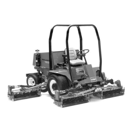
- Page 1 FORM NO. 3318-295 GB Rev A OPERATOR’S 0001 MODEL NO. 03702—6 & UP MANUAL 0001 MODEL NO. 03704—6 & UP ® ® REELMASTER 4500-D TRACTION UNITS...
-
Page 2: Table Of Contents
The model and serial number for the cutting unit is on a plate that is mounted on the top front of the center cutting unit. Use model and serial number in all correspondence and when ordering parts. To order replacement parts from an authorized TORO Distributor, supply the following information: Model and serial numbers of the machine. -
Page 3: Safety
Safety Training WARNING—Petrol is highly flammable. • Store fuel in containers specifically Read the instructions carefully. Be familiar with designed for this purpose. the controls and the proper use of the equipment. • Refuel outdoors only and do not smoke while refueling. - Page 4 • stay alert for bumps and hollows and other adjustment can be made from the operator’s hidden hazards; position. • never mow across the face of the slope, • before clearing blockages; unless the lawn mower is designed for this •...
- Page 5 Sound & Vibration Levels Sound Levels This unit has an equivalent continuous A-weighted sound pressure at the operator ear of: 90 dB(A), based on measurements of identical machines per SAE J1174—Mar 85 procedures. This unit has a sound power level of 105 dB(A)/1pW, based on measurements of identical machines per pro- cedures outlined in Directive 79/113/EEC and amend- ments...
- Page 6 Symbol Glossary Caustic liquids, Poisonous Electrical shock, High pressure High pressure High pressure Crushing of Crushing of chemical burns to fumes or toxic electrocution fluid, injection spray, erosion of spray, erosion of fingers or hand, toes or foot, force fingers or hand gases, asphyxiation into body flesh...
- Page 7 Eye protection Head protection Hearing Caution, toxic First aid Flush with water Engine Transmission must be worn must be worn protection must risk be worn Hydraulic Brake system Fire, open light Coolant (water) Intake air Exhaust gas Pressure & smoking system prohibited Level...
- Page 8 Engine coolant Engine coolant f Engine Engine intake/ Engine intake/ Engine intake/ Engine start Engine stop pressure ilter lubricating oil combustion air combustion air air filter pressure pressure n/min Engine failure/ Engine rotational Choke Primer (start aid) Electrical preheat Transmission oil Transmission oil Transmission oil malfunction speed/frequency...
-
Page 9: Specifications
Specifications Engine: Mitsubishi, four-cycle, four-cylinder, 139 cu-in. hydraulic oil level and high engine temperature pro- displacement, water cooled diesel engine. Rated 40 hp tection systems stop the engine. @ 2,300 rpm, 21:1 compression ratio. Low idle—1,200 rpm, high idle—2,500 rpm. Injection Timing –20° Warning Systems: BTDC. - Page 10 Clip (variable to match conditions): 5-Blade Cutting Unit: .176 in. per mph (0.352 in. at 2 mph-1.32 in. at 7.5 mph) 7-Blade Cutting Unit: .126 in. per mph (0.252 in. at 2 mph -945 in.at 7.5 mph) 11-Blade Cutting Unit: .080 in.
-
Page 11: Before Operating
Before Operating CHECK THE ENGINE OIL DAILY Park the machine on a level surface. Release the engine cover latches (Fig. 1). Open the engine cover and hold it upright Remove the dipstick, wipe it clean, reinstall it into the fill tube and pull it out again;... - Page 12 of filler neck with No. 2 diesel fuel. Then install the cap. DANGER Because diesel fuel is flammable, use caution when storing or handling it. Do not smoke while filling the fuel tank. Do not fill the fuel tank while the engine is running, hot, or when the machine is in an enclosed area.
-
Page 13: Controls
Controls Seat Adjustment (Fig. 6) The seat adjusting lever allows 15 cm (5.9 inches) fore and aft adjustment in 15 mm increments. Arm Rest (Fig. 7) The arm rest pivots up and down. Backrest Knob (Fig. 7)—The backrest knob adjusts the back- rest angle from 5–20 degrees. - Page 14 indicator light and audible signal warn of excessively high hydraulic temperature. Hydraulic Oil Level Warning (Fig. 8)—A warning indicator light and audible signal warn of low hydraulic oil level. If the oil level drops further, the engine will automatically stop. The engine cannot be restarted until the oil supply is brought to a safe level.
- Page 15 IMPORTANT: The cam lever nut (Fig. 9 inset) can be tightened if the limiter stop will not hold traction pedal in desired position. Transport Latches (Fig. 9 and 10)—Latches secure the cutting units in upright position for transport. The latch for the front cutting units is foot-operated (Fig.
- Page 16 OFF. Parking Brake Lever (Fig. 11)—Pull the lever up to lock the brake. To release the brake, pull up on the lever, press the button and lower lever. The brake must be engaged to start the engine. Always engage the parking brake before getting 16 7 off the seat.
-
Page 17: Operating
Operating Instructions STARTING AND STOPPING Sit on the seat, keep your foot off the traction pedal. Make sure the parking brake is engaged (Fig. 11). The traction pedal and the mow/backlap lever must be in neutral. 16 7 If the engine or air temperature is below 45°–50° F (7–10° C), press and hold the engine preheat switch in until indi- cator burns brightly (Fig. - Page 18 Apply the parking brake, turn the ignition key ON. Push the warning indicator light button (Fig. 13). All lights should illuminate and the alarm will sound. Note: The alarm will continue to sound until the prob- lem is corrected or until the alarm silence button is pressed.
- Page 19 Note: There is a 1–2 second delay between rising off the seat and the engine shuts off. Engage the parking brake, move the Mow-Backlap lever to NEUTRAL, start the engine, disengage the hand brake and raise off the seat. If the engine stops, the interlock system is operating.
- Page 20 IMPORTANT: Running the machine with the bypass valve open will cause the hydraulic system to overheat. If towing with the front wheel motors disengaged, the Tow Bar Assembly, Toro part no. 58-7020, must be used. OPERATING CHARACTERISTICS Familiarization—Before mowing grass, practice in an open Figure 18 area.
- Page 21 does not follow the motion of the lift control lever during oper- ation, adjust the set screw(s) as required. When permanent use of cross-cut link is not desired, you can remove it by unscrewing the lift control knob and loosening the set screw.
-
Page 22: Maintenance
Hydraulic System Fluid: Refer to Hydraulic Oil Specifications (Page 8). Do not use the engine oil in the hydraulic system. Filters: Hydraulic Oil (Toro part no. 58-6610); Air (Toro part no. 27-7110); Fuel (Toro part no. 60-5420); Engine Oil (Toro part no. - Page 23 LUBRICATION Areas to lubricate are pictured in figures 23–25. Use No. 2 lithium-based grease. Also, grease the fitting on the Reel Control Valve (not shown), under the right console. Note: Remove the plastic caps over the fittings on the floating- or fixed-head kit pivots and replace them after greasing (Fig.
- Page 24 Figure 28 Oil Filter Figure 26 Precleaner bowl Mounting band Dust cup Baffle Filter Gasket Figure 29 Drain Outlet Plunger Filter Figure 27 Drain plug Figure 30...
- Page 25 Figure 32 Figure 35 Oil cooler Hydraulic drain plug Radiator Figure 33 Hydraulic sight glass arrows Figure 36 Hydraulic filter Figure 34 Hydraulic reservoir cover Figure 37 Hydraulic system breather...
- Page 26 CHECKING PLANETARY GEAR DRIVE Initially, check the oil level after 50 operating hours and check every 800 hours after that. The oil capacity is approximately 30 oz. (885 ml) high-quality 80–90 weight Gear Lube. To check the oil level, the oil should be at the bottom of the check/drain plug hold (Fig.