Table of Contents
Advertisement
Quick Links
CALIBRATION PROCEDURE
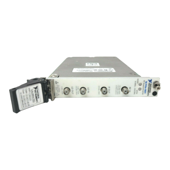
NI PXIe-5601
This document contains information for calibrating the National Instruments PXIe-5601 (NI 5601)
RF downconverter. For more information about calibration, visit
Contents
Software Requirements............................................................................................................. 2
Documentation Requirements .................................................................................................. 2
Calibration Interval................................................................................................................... 2
Test Equipment......................................................................................................................... 2
Test Conditions......................................................................................................................... 4
Calibration Procedures ............................................................................................................. 5
Initial Setup....................................................................................................................... 6
Test System Characterization ........................................................................................... 6
Power Splitter Reference Output.............................................................................. 6
Power Sensor Zero/Calibration ................................................................................ 6
RF Input Calibration................................................................................................. 6
IF Output Calibration................................................................................................ 9
As-Found and As-Left Limits........................................................................................... 10
Verification....................................................................................................................... 10
Absolute Gain Accuracy Verification ...................................................................... 10
Average Noise Level Verification............................................................................ 17
LO Output Power Verification ................................................................................. 19
Instantaneous Bandwidth Verification ..................................................................... 21
Gain Compression Verification ................................................................................ 24
Adjustment........................................................................................................................ 28
Initial Connections.................................................................................................... 28
Reference Level Adjustment for RF Frequencies ≥120 MHz .................................. 28
IF Attenuation Calibration Adjustment .................................................................... 33
IF Response Adjustment........................................................................................... 36
Reference Level Adjustment for RF Frequencies ≤120 MHz.................................. 41
Appendix A: Reference Level Calibration Power .................................................................... 44
Where to Go for Support .......................................................................................................... 45
ni.com/calibration
.
Advertisement
Table of Contents

Related Manuals for National Instruments NI PXIe-5601


Summary of Contents for National Instruments NI PXIe-5601
-
Page 1: Table Of Contents
CALIBRATION PROCEDURE NI PXIe-5601 This document contains information for calibrating the National Instruments PXIe-5601 (NI 5601) RF downconverter. For more information about calibration, visit ni.com/calibration Contents Software Requirements......................2 Documentation Requirements ....................2 Calibration Interval........................2 Test Equipment......................... 2 Test Conditions......................... 4 Calibration Procedures ...................... -
Page 2: Software Requirements
Documentation Requirements You might find the following documents helpful as you perform the calibration procedure: • NI PXIe-5601 Specifications—Provides the published specification values for the NI 5601. Refer to the most recent NI PXIe-5601 Specifications online at ni.com/manuals •... - Page 3 6 GHz......<1.45% 7 GHz......<1.26% Signal generator (LO source) NI PXI/PXIe-5652 — Signal generator (RF source) Anritsu MG3692B Frequency range: 10 MHz to 6.6 GHz Power level: -60 dBm to 20 dBm NI PXIe-5601 Calibration Procedure | © National Instruments | 3...
-
Page 4: Test Conditions
Verify that all connections to the device, including front panel connections, are secure. • Maintain an ambient temperature of 23 °C ±5 °C. • Keep the relative humidity between 10% and 90%, noncondensing. 4 | ni.com | NI PXIe-5601 Calibration Procedure... -
Page 5: Calibration Procedures
Adjustment—Perform an adjustment on the NI 5601. Refer to the Adjustment section in this document. Reverification—Repeat the verification procedure for the NI 5601 to ensure that it is operating within the device specifications after adjustment. NI PXIe-5601 Calibration Procedure | © National Instruments | 5... -
Page 6: Initial Setup
IF Attenuation Calibration Adjustment Connect the power splitter input to the RF source output through the 3.5 mm-to-3.5 mm cable. Connect power sensor A to the previously designated reference output of the power splitter. 6 | ni.com | NI PXIe-5601 Calibration Procedure... - Page 7 RF Input Calibration Factor = Channel B Power - Channel A Power Figure 1. RF Input Calibration (Without Attenuator) Equipment Setup RF Source Power Sensor A Power Meter Channel A Power Sensor B Power Splitter Power Meter Power Meter Channel B NI PXIe-5601 Calibration Procedure | © National Instruments | 7...
- Page 8 1,000 MHz, and so on. Calculate the RF Input Attenuated Calibration Factor (dB) for each frequency using the following equation: RF Input Attenuated Calibration Factor = Channel B Power - Channel A Power 8 | ni.com | NI PXIe-5601 Calibration Procedure...
-
Page 9: If Output Calibration
Measure the channel A power and the spectrum analyzer power, using the appropriate frequency for the power sensor, using the following settings: • RF source power (for both 53 MHz and 187.5 MHz): 0 dBm • Reference level: 0 dBm NI PXIe-5601 Calibration Procedure | © National Instruments | 9... -
Page 10: As-Found And As-Left Limits
Limits in the following sections are based upon the August 2009 edition of Note the NI PXIe-5601 Specifications. Refer to the most recent specifications online at . If a more recent edition of the specifications is available, ni.com/manuals recalculate the limits based upon the latest specifications. - Page 11 The preceding figure shows the NI PXI-5652, but you can also use the Note NI PXIe-5652. The figure shows spectrum analyzer connections. The 30 dB attenuator is used only for reference levels <-30 dBm. NI PXIe-5601 Calibration Procedure | © National Instruments | 11...
- Page 12 Table 3. NI 5601 Center Frequency Beginning (MHz) Ending (MHz) Step (MHz) — — 6,400 6,590 — — 10. Commit the settings to hardware using the niRFSA Initiate VI or the niRFSA_Initiate function. 12 | ni.com | NI PXIe-5601 Calibration Procedure...
- Page 13 Analyzer Power. Correct the Spectrum Analyzer Power using the appropriate IF Calibration Factor for the IF frequency in Table 5 and the following formula: Corrected Spectrum Analyzer Power = Spectrum Analyzer Power + IF Calibration Factor NI PXIe-5601 Calibration Procedure | © National Instruments | 13...
- Page 14 Set the Driver Setup portion of the option string niRFSA_initWithOptions parameter to DriverSetup=Digitizer:<external> Lock the NI PXI/PXIe-5652 to the Reference Clock used by the external test equipment. Use the niRFSA Configure Ref Clock VI or the niRFSA_ConfigureRefClock function. 14 | ni.com | NI PXIe-5601 Calibration Procedure...
- Page 15 14. Recall the NI 5601 Stored Gain for each test frequency using the niRFSA Downconverter Gain property or the attribute. NIRFSA_ATTR_DOWNCONVERTER_GAIN 15. Calculate the Absolute Gain Accuracy using the following formula: Absolute Gain Accuracy = NI 5601 Calculated Gain - NI 5601 Stored Gain NI PXIe-5601 Calibration Procedure | © National Instruments | 15...
- Page 16 300 MHz to <400 MHz ±1.4 dB ±0.65 dB 400 MHz to <3 GHz ±1.3 dB ±0.65 dB 3 GHz to <5.5 GHz ±1.3 dB ±0.65 dB 5.5 GHz to <6.6 GHz ±1.3 dB ±0.65 dB 16 | ni.com | NI PXIe-5601 Calibration Procedure...
-
Page 17: Average Noise Level Verification
Set the Driver Setup portion of the option string niRFSA_initWithOptions parameter to DriverSetup=Digitizer:<external> Lock the NI PXI/PXIe-5652 to the Reference Clock used by the external test equipment. Use the niRFSA Configure Ref Clock VI or the niRFSA_ConfigureRefClock function. NI PXIe-5601 Calibration Procedure | © National Instruments | 17... - Page 18 13. Calculate the NI 5601 Input Noise using the following formula: NI 5601 Input Noise = Measured Noise + IF Calibration Factor - NI 5601 Stored Gain 14. Compare the NI 5601 Input Noise to the limits in Table 11. 18 | ni.com | NI PXIe-5601 Calibration Procedure...
-
Page 19: Lo Output Power Verification
Connect a 50 Ω terminator to the NI 5601 IF OUT connector. Connect the other power splitter output to the NI 5601 LO IN connector through the 3.5 mm-to-3.5 mm adapter. NI PXIe-5601 Calibration Procedure | © National Instruments | 19... - Page 20 Configure Spectrum Frequency VI or the function. Set the span niRFSA_ConfigureSpectrumFrequencyCenterSpan parameter to 100 Hz. Table 12. NI 5601 Center Frequency Start (MHz) Stop (MHz) Step (MHz) 6,510 6,600 — — 20 | ni.com | NI PXIe-5601 Calibration Procedure...
-
Page 21: Instantaneous Bandwidth Verification
Connect the RF source to the power splitter input through the 3.5 mm-to-3.5 mm cable. Connect the power splitter reference output to power sensor A. Ensure that the 50 Ω terminator is connected to the NI 5601 LO OUT connector. NI PXIe-5601 Calibration Procedure | © National Instruments | 21... - Page 22 Set the Driver Setup portion of the option string niRFSA_initWithOptions parameter to DriverSetup=Digitizer:<external> Lock the NI PXI/PXIe-5652 to the Reference Clock used by the external test equipment. Use the niRFSA Configure Ref Clock VI or the niRFSA_ConfigureRefClock function. 22 | ni.com | NI PXIe-5601 Calibration Procedure...
- Page 23 14. Set the spectrum analyzer center frequency to the IF Output Frequency listed in Table 15. 15. Record the spectrum analyzer peak marker power as Spectrum Analyzer Power at IF Center Frequency. You do not need to correct this reading for the IF Calibration Factor. NI PXIe-5601 Calibration Procedure | © National Instruments | 23...
-
Page 24: Gain Compression Verification
Connect the NI 5601 IF OUT connector to the spectrum analyzer input through the 3.5 mm-to-3.5 mm cable. Connect the RF source to the power splitter input through the 3.5 mm-to-3.5 mm cable. 24 | ni.com | NI PXIe-5601 Calibration Procedure... - Page 25 Create a new session for the NI 5601 using the niRFSA Initialize With Options VI or the function. Set the Driver Setup portion of the option string niRFSA_initWithOptions parameter to DriverSetup=Digitizer:<external> NI PXIe-5601 Calibration Procedure | © National Instruments | 25...
- Page 26 120 MHz to < 330 MHz 53 MHz 330 MHz to 6.6 GHz 187.5 MHz 12. Set the RF source to the center frequency in Table 17. 13. Wait at least 1 second. 26 | ni.com | NI PXIe-5601 Calibration Procedure...
- Page 27 1 dB Compression Fine 10 MHz to <120 MHz >-2 dBm 120 MHz to <330 MHz >2 dBm 330 MHz to 6.6 GHz >6 dBm Note: At RF input, -10 dBm reference level. NI PXIe-5601 Calibration Procedure | © National Instruments | 27...
-
Page 28: Adjustment
IF attenuation settings to use at a given reference level and RF frequency. After the RF and IF gain and attenuations are found, the NI 5601 determines the appropriate amplitude correction for those settings. 28 | ni.com | NI PXIe-5601 Calibration Procedure... - Page 29 Each step opens a new calibration session. Enter the appropriate password for Note this VI. The default password for password-protected operations is NI PXIe-5601 Calibration Procedure | © National Instruments | 29...
- Page 30 Index Attenuator Band (MHz) (MHz) (MHz) (MHz) (MHz) (MHz) 0-64 Enabled — — — 187.5 517.5 688.5 1,800 787.5 1,987.5 1,950 3,000 2,137.5 3,187.5 3,000 5,700 2,812.5 5,512.5 5,800 6,600 5,612.5 6,412.5 30 | ni.com | NI PXIe-5601 Calibration Procedure...
- Page 31 Table 20. NIRFSA_ATTR_MECHANICAL_ATTENUATOR_ENABLED 23. Commit the settings to hardware using the niRFSA Initiate VI or the niRFSA_Initiate function. 24. Tune the RF source to the RF start frequency in Table 20. NI PXIe-5601 Calibration Procedure | © National Instruments | 31...
- Page 32 Keeping the signal generator enabled reduces the wear on the RF signal generator relays. After making a connection change and enabling your generator, wait 5 seconds for the system to settle. 32 | ni.com | NI PXIe-5601 Calibration Procedure...
-
Page 33: If Attenuation Calibration Adjustment
VI to IF Attenuation Calibration, or set the calibrationStep parameter in the function to NIRFSA_VAL_EXT_CAL_IF_ATTENUATION_CALIBRATION Initialize the NI PXI/PXIe-5652 using the niRFSG Initialize VI or the niRFSG_init function. NI PXIe-5601 Calibration Procedure | © National Instruments | 33... - Page 34 21. Configure the IF attenuation for the device by setting the niRFSA IF1 Attenuation and IF2 Attenuation properties or the NIRFSA_ATTR_IF1_ATTEN_VALUE attributes. This configuration ensures that Table 22 NIRFSA_ATTR_IF2_ATTEN_VALUE references all possible value pairs for IF1 and IF2. 34 | ni.com | NI PXIe-5601 Calibration Procedure...
- Page 35 Commit or by calling the function with the niRFSA_CloseExtCal action parameter set to NIRFSA_VAL_EXT_CAL_COMMIT 32. Close the niRFSG session using the niRFSG Close VI or the function. niRFSG_close NI PXIe-5601 Calibration Procedure | © National Instruments | 35...
-
Page 36: If Response Adjustment
Each step opens a new calibration session. Enter the appropriate password for Note this VI. For password-protected operations, the default password is 36 | ni.com | NI PXIe-5601 Calibration Procedure... - Page 37 Freq. Freq. Freq. Step Freq. Atten. Atten. Filter (MHz) (MHz) (MHz) (MHz) (MHz) (dB) (dB) Band 187.5 1,000 1,277.5 1,097.5 187.5 MHz, Wide 187.5 1,000 1,227.5 1,147.5 187.5 MHz, Narrow NI PXIe-5601 Calibration Procedure | © National Instruments | 37...
- Page 38 Reference level 20 dBm Resolution bandwidth 200 Hz 20. Set the RF source frequency to the RF Frequency in Table 23 or 24, corresponding to the module revision of your NI 5601. 38 | ni.com | NI PXIe-5601 Calibration Procedure...
- Page 39 27 in an array. You can repeat steps 19 through 27 with the first spectrum analyzer measurement at a reference level similar to the second measurement. This repetition reduces internal attenuator switching. The second measurement must follow the settings in Table 26. NI PXIe-5601 Calibration Procedure | © National Instruments | 39...
- Page 40 33. Close the external calibration by calling the niRFSA Close Ext Cal VI with the action parameter set to Commit or by calling the function with the niRFSA_CloseExtCal action parameter set to NIRFSA_VAL_EXT_CAL_COMMIT 34. Close the niRFSG session using the niRFSG Close VI or the function. niRFSG_close 40 | ni.com | NI PXIe-5601 Calibration Procedure...
-
Page 41: Reference Level Adjustment For Rf Frequencies ≤120 Mhz
12. Call the niRFSA Initiate VI or the function. niRFSA_Initiate 13. Configure the NI 5601 RF signal path by setting the niRFSA RF Path Selection property to RF band 4 or by setting the NIRFSA_ATTR_CAL_RF_PATH_SELECTION attribute NIRFSA_VAL_EXT_CAL_RF_BAND_4 NI PXIe-5601 Calibration Procedure | © National Instruments | 41... - Page 42 26. Wait 750 ms or until power sensor A settles to 0.1% of source power, whichever is greater. 27. Measure the Channel A Power. Calculate RF Input Power using the following equation: RF Input Power = Channel A Power + RF Input Calibration Factor 42 | ni.com | NI PXIe-5601 Calibration Procedure...
- Page 43 Commit or by calling the function with the niRFSA_CloseExtCal action parameter set to NIRFSA_VAL_EXT_CAL_COMMIT 37. Close the niRFSG session using the niRFSG Close VI or the function. niRFSG_close NI PXIe-5601 Calibration Procedure | © National Instruments | 43...
-
Page 44: Appendix A: Reference Level Calibration Power
The power level used for reference level calibration is determined by the attenuation set in the NI 5601. The following table shows the power level as a function of the attenuation index. Table 30. Power Level RF Attenuation Index RF Source Power (dBm) 44 | ni.com | NI PXIe-5601 Calibration Procedure... -
Page 45: Where To Go For Support
NI product. Refer to the Export Compliance Information at ni.com/legal/export-compliance for the National Instruments global trade compliance policy and how to obtain relevant HTS codes, ECCNs, and other import/export data. © 2010–2013 National Instruments. All rights reserved.
Need help?
Do you have a question about the NI PXIe-5601 and is the answer not in the manual?
Questions and answers