Advertisement
Quick Links
2006-08
MAINTENANCE MANUAL
Automatic Dicing/Cutting Saws
UHESME*054C
DAD321
DAC351
DAD361
SOFTWARE VERSION 5.4 SERIES
Copyright of this document is owned by Disco Corporation ("Disco").
No part of this document may be copied or reproduced in any form
or by any means, without the express written permission of Disco.
Also, this document may not be disclosed or transferred to third
parties.
This document is printed on recyclable Lint-Free paper.
- The blue paper is recyclable as used paper just like plain paper.
- The cover paper and adhesive portions are non-recyclable.
(Remove the cover and adhesive portions before recycling.
Recycle the blue paper only.)
Advertisement

Related Manuals for DISCO DAD321


Summary of Contents for DISCO DAD321
- Page 1 Copyright of this document is owned by Disco Corporation ("Disco"). No part of this document may be copied or reproduced in any form or by any means, without the express written permission of Disco. Also, this document may not be disclosed or transferred to third parties.
- Page 2 If you modify the machine without prior consent of DISCO or repair it in a manner not stated in this manual, the safety assurance features of the machine may be seriously affected.
- Page 3 Hazard level The safety precautions set forth in this document are classified into DANGER, WARNING and CAUTION categories which represent three degree of hazards latent in the machine. These categories are defined as detailed below in accordance with the seriousness and probability level of the hazard. In addition to the above three safety precaution levels, CAUTION without the safety alert symbol ( ) and NOTICE are used to give safety usage instructions to the...
- Page 4 Safety label Safety labels are affixed to the hazardous sections of the machine. Before using the machine, verify the label positions and thoroughly understand the precautions and warning indicated by the safety labels. Label Hazard Level Meaning of Label Rotary Blade It is possible that your hands and Label fingers may be cut by the rotating...
- Page 5 The person who operates the machine to process workpieces. Minimum retention period of the maintenance functional parts Maintenance functional parts required for repair or modification will be retained by Disco for at least seven years after the B/L date. Intro-1...
- Page 6 Part replacement When replacing parts, be sure to use the genuine DISCO brand. If any parts other than DISCO's genuine parts are used, DISCO shall assume no liability for any damage of any kind. When replacing components using the UL-listed parts, be sure to use the UL- listed parts to be installed.
- Page 7 Notation of part number In this document, the part numbers are shown as follows. XXXX-XXXXXX-X (YYYYYYYY--Y) New style part no. Former style part no. Intro-3...
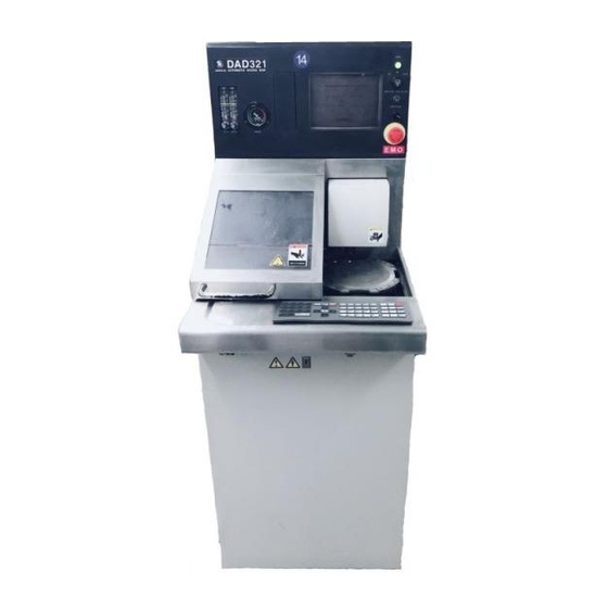
- Page 8 Section diagram The diagram and table below show the names and functions of each section. Cutting section Operation control section Name Function Cutting Section Cuts workpieces. Operation Control Keys on the operation panel are used for data entries, Section and the function keys perform operations. Also, the monitor displays operation-related information and microscope images in accordance with operation panel manipulation.
- Page 9 External view The diagram and the table below show the external view, names and functions of main constituents. Pilot lamp Monitor Disk drive POWER lamp Flowmeter Key switch Maintenance switch Vacuum gauge Light intensity Splash cover adjustment dial Operation panel EMO switch Microscope Chuck table...
- Page 10 Axis arrangement diagram The diagram and the table below show axis arrangement, names and functions of each axis. Spindle axis Z-axis θ -axis (except 351) Y-axis X-axis Main body frame Front Name Function X-axis Moves the chuck table to the right and the left. Y-axis Moves the spindle axis and the microscope forward and backward.
- Page 11 CONTENTS READ CAREFULLY BEFORE USING THIS MANUAL INTRODUCTION ..........Intro-1 CONTENTS ..........Contents-1 A. IMPORTANT SAFETY INFORMATION ... A-1 1. General Safety Precautions ..............A-2 2. Safety Precautions to Be Observed During Operation......A-4 3. Inherently Hazardous Areas and Ways to Avoid Hazards....A-10 3-1.
- Page 12 CONTENTS C. MACHINE COMPONENTS AND FUNCTIONS..........C-1 1. Machine Outer Cover ................C-2 2. Axis Section ..................C-5 2-1. Axis Arrangement ..................C-6 2-2. X-axis Section....................C-7 2-3. Y-axis Section ....................C-9 2-4. Z-axis Section....................C-11 2-5. θ-axis Section ....................C-13 2-6. Microscope Section ..................C-16 2-7.
- Page 13 CONTENTS 2-1-2. Mounting the flange................D-24 2-2. Wheel Mount Replacement ................. D-26 2-2-1. Removing the wheel mount..............D-28 2-2-2. Mounting the wheel mount ..............D-30 3. Sensor Adjustment ................D-32 3-1. Air Pressure Sensor Adjustment..............D-33 3-1-1. Removing the outer covers ..............D-34 3-1-2.
- Page 14 CONTENTS F. TROUBLESHOOTING ........F-1 1. Remedies for Problems Invoking No Error Code Indication - Problems at Power ON - ..............F-2 1-1. Power Receiving Lamp Problems..............F-3 1-2. Main Circuit Breaker Problems ..............F-4 1-3. Main Power Supply Problems................ F-5 1-4.
- Page 15 CONTENTS 1-3-3. Cleaning the spindle main body ............G-30 1-3-4. Cleaning the edge of the spindle............G-31 1-3-5. Completion of spindle cleaning ............G-32 FYI: Possible problems of the spindle due to stains ........G-32 2. Maintenance and Inspection to Be Done Every Day......G-33 2-1.
- Page 16 CONTENTS 6-3. Cleaning the Spindle Coolant Water Path............G-72 6-3-1. Cleaning the spindle coolant water path ..........G-73 6-3-2. Completion of cleaning the spindle coolant water path ......G-75 7. Maintenance to Be Performed at 365-Day (Recommended) Intervals ..............G-76 7-1. Adjusting the Timing Belt ................G-77 7-1-1.
- Page 17 CONTENTS 2-4. Replacing the Solenoid Valve ..............H-32 2-4-1. Removing the machine outer cover............ H-33 2-4-2. Replacing the solenoid valve.............. H-35 2-4-3. Completion of replacing the solenoid valve ........H-37 3. Consumables to Be Replaced at 1000-Day (Recommended) Intervals ..............H-38 3-1.
-
Page 18: Important Safety Information
A. IMPORTANT SAFETY INFORMATION Contents of this chapter This chapter describes various precautions to assure safety in the operation and safety protective functions employed in this machine. Section Title Contents General Safety Precautions - Safety precautions to be understood before operation - Safety precautions to be observed during operation Safety Precautions to Be... - Page 19 The machine must be inspected on a regular basis. If any accidents occur while an appropriate regular inspection program is not adhered to, DISCO is not responsible for the results. - Maintenance personnel Maintenance must be conducted by qualified personnel who have received the maintenance training.
- Page 20 In the case of relocation or disposal of the machine, the presentation of detailed precautionary notes and the management of new installation site data will be done by DISCO. If you want to relocate or disposal the machine, contact your...
Need help?
Do you have a question about the DAD321 and is the answer not in the manual?
Questions and answers