Advertisement
Quick Links
to register your set, or to order replacement parts please visit
SAVE THIS ASSEMBLY MANUAL FOR FUTURE REFERENCE IN THE EVENT THAT
Made in China |
Model # 1701014
average 2 person assembly time
assembly time may vary based on skill level
For the most up to date assembly manual,
www.backyarddiscovery.com
YOU NEED TO ORDER REPLACEMENT PARTS.
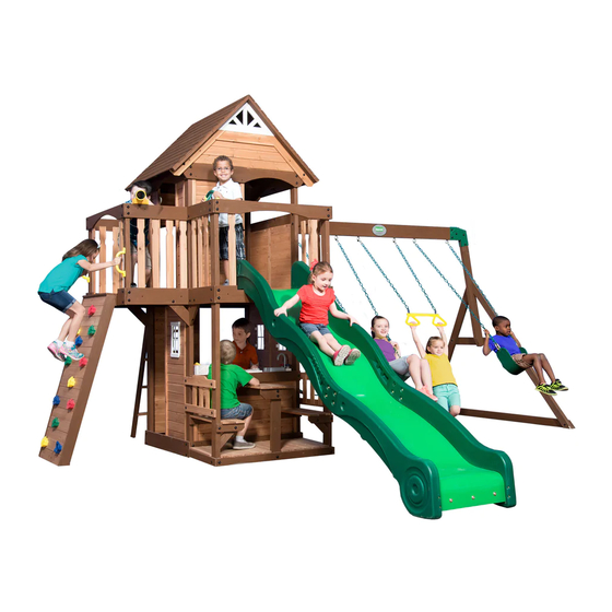
Wooden Swing Set
Owner's Manual & Assembly Instructions
MANUFACTURED BY:
Backyard Discovery
3305 Airport Drive
Pittsburg, KS 66762
800-856-4445
Advertisement

Related Manuals for Backyard Discovery Mount Triumph


Summary of Contents for Backyard Discovery Mount Triumph
- Page 1 MANUFACTURED BY: Wooden Swing Set Backyard Discovery 3305 Airport Drive Pittsburg, KS 66762 Model # 1701014 Owner's Manual & Assembly Instructions 800-856-4445 average 2 person assembly time assembly time may vary based on skill level For the most up to date assembly manual, to register your set, or to order replacement parts please visit www.backyarddiscovery.com...
- Page 2 INSTALLATION SERVICES AVAILABLE! Need a helping hand? Let our team of professionals handle the installation for you! *Installation services are only available to U.S. customers. With Go Configure, we bring you 18 years of experience right to your doorstep. We service a wide array of indoor and outdoor recreation products that most consumers don’t have the time or ability to deliver &...
- Page 3 Please Read This Before Starting Assembly MISSING A PART? CALL US BEFORE GOING BACK TO THE STORE Th e store where you made your purchase does not stock parts for this item. If you have assembly questions or you are missing or have damaged parts, please call you can also visit www.backyarddiscovery.com or e-mail customerservice@backyarddiscovery.com...
- Page 4 Botanical, Adventure Playsets, and Leisure Time Products. Backyard Discovery warrants that this product is free from defect in materials and workmanship for a period of one (1) year from the original date of purchase. Th is one (1) year warranty covers all parts including wood, hardware, and accessories. All wood carries a fi ve (5) year pro-rated warranty against rot and decay. Refer to the schedule below for charges associated with replacement of parts under this Limited Warranty.
- Page 5 Operating Instructions and Safety Warnings WARNING: BURN HAZARD • Pay special attention to plastic and metal surfaces as they may be hot enough to cause burns. • Always check the temperature of the product before NOTE: letting your children play on it. •...
- Page 6 Please Read This Before Starting Assembly Positioning Your Playcenter Suggested Playground Surfacing • Th e playcenter is designed to be installed on a level • Do not install home playground equipment over surface by an adult with an adult helper. Place concrete, asphalt, packed earth, grass, carpet, or any in a fl at area of your yard to minimize ground other hard surface.
- Page 7 Please Read This Before Starting Assembly APPENDIX A The following information is from the United States X3.1.3.2 Do not install loose-fi ll surfacing over hard surfaces such as concrete or asphalt. Consumer Product Safety Commission’s Information X3.1.4 Poured-In-Place Surfaces or Pre-Manufactured Sheet for playground surfacing material;...
- Page 8 Check all moving parts including swing seats, third party person or service to assemble this product. ropes, cables, and chains for wear, rust, or other Backyard Discovery assumes no responsibility or deterioration. Replace as needed. liability for any charge incurred by the Customer for any assembly services’...
- Page 9 About Our Wood Backyard Discovery uses 100% Cedar (C. Lanceolata) wood. Although we take great care in selecting the best quality lumber available, wood is still a product of nature and susceptible to weathering which can change the appearance of your set.
- Page 10 Assembly Tips Protrusion Hazard Incorrect Correct If you see exposed threads and your bolt protrudes beyond the T-Nut you may have over tightened the bolt or used incorrect hardware. If you’ve overtightened, remove the bolt and add washers to eliminate the protrusion.
- Page 11 Assembly Tips ASSEMBLY TIP: Keep an eye out for these boxes which will contain helpful pictures and information making the assembly process as quick and painless as possible. Sorting Wood When removing the wood from the boxes we recommend arranging them by part number before you begin assembly.
- Page 12 Tools Required for Installation: (These are the tools that are generally required for assembly of our outdoor products. These tools are not included with the outdoor product purchase.) (Level 24") (Square) (Open End Wrenches 1/2") (Phillips Screw Driver) (Tape Measure) (Claw Hammer) (Rubber Mallet - Optional) (Drill Attachments:...
- Page 13 Basic Setup Dimensions Place the set on level ground, not less than 6 ft [2 m] from any structure or obstruction such as a fence, garage, house, overhanging branches, laundry lines, or electrical wires. 27'-7 5/8" General Information: 15'-7 5/8" 15'-3 1/8"...
- Page 14 Parts Identification Wood Components (NOT TO SCALE) E1 - RIGHT REAR UPRIGHT - W2A02080 1 3/8"x3 3/8"x51 3/4" (36x86x1314) E2 - LEFT REAR UPRIGHT - W4L07493 1 3/8"x3 3/8"x51 3/4" (36x86x1314) E3 - LEFT FRONT UPRIGHT - W4L07494 1 3/8"x3 3/8"x51 3/4" (36x86x1314) E4 - RIGHT FRONT UPRIGHT - W4L07495 1 3/8"x3 3/8"x51 3/4"...
- Page 15 Parts Identification Wood Components (NOT TO SCALE) E73 - RIGHT RAIL - W4L07623 1 3/8"x3 3/8"x54 7/8" (36x86x1395) E77 - ANGLE BRACE - W4L07631 1 3/8"x3 3/8"x74 3/8" (36x86x1890) F1 - RIGHT BALCONY UPRIGHT - W4L07506 1 3/8"x2 3/8"x31 3/4" (36x60x805) F2 - LEFT BALCONY UPRIGHT - W4L07507 1 3/8"x2 3/8"x31 3/4"...
- Page 16 Parts Identification Wood Components (NOT TO SCALE) H77 - LEFT UPRIGHT - W4L07617 1"x3 3/8"x58" (24x86x1474) H78 - RIGHT UPRIGHT - W4L07618 1"x3 3/8"x58" (24x86x1474) H79 - END SUPPORT - W4L07632 1"x3 1/2"x42" (24x86x1072) H80 - GROUND BOARD - W4L07630 1"x3 3/8"x87 3/8"...
- Page 17 Parts Identification Wood Components (NOT TO SCALE) J9 - FLOOR JOIST - W4L07603 1"x2 3/8"x20 1/4" (24x60x513) K1 - GROUND BOARD - W4L07489 5/8"x5 1/4"x41 7/8" (16x134x1064) K2 - GROUND BOARD - W4L07490 5/8"x5 1/4"x41 7/8" (16x134x1064) K3 - GROUND BOARD - W4L07491 5/8"x5 1/4"x40 1/2"...
- Page 18 Parts Identification Wood Components (NOT TO SCALE) K9 - LEFT BALCONY WALL RAIL - W4L07500 5/8"x5 1/4"x20 3/4" (16x134x528) K10 - FRONT BALCONY WALL RAIL - W4L07501 5/8"x5 1/4"x40 5/8" (16x134x1032) K11 - LEFT SIDE WALL BOARD - W4L07508 5/8"x5 1/4"x41 7/8" (16x134x1064) K12 - ARCHED WALL RAIL - W4L07579 5/8"x5 1/4"x40 5/8"...
- Page 19 Parts Identification Wood Components (NOT TO SCALE) L1 - ARCHED WALL RAIL - W4L07514 5/8"x4 3/8"x40 5/8" (16x112x1032) L2 - WALL RAIL - W4L07515 5/8"x4 3/8"x22 7/8" (16x112x582) L3 - WALL RAIL - W4L07576 5/8"x4 3/8"x20 7/8" (16x112x529) L4 - ARCHED WALL RAIL - W4L07577 5/8"x4 3/8"x43 1/2"...
- Page 20 Parts Identification Wood Components (NOT TO SCALE) M6 - COUNTER TOP - W4L07605 5/8"x3 3/8"x37 5/8" (16x86x957) M7 - COUNTER TOP - W4L07606 5/8"x3 3/8"x38 5/8" (16x86x981) M8 - FLOOR BOARD - W4L07607 5/8"x3 3/8"x20 1/8" (16x86x512) M9 - FLOOR BOARD - W4L07608 5/8"x3 3/8"x20 1/8"...
- Page 21 Parts Identification Wood Components (NOT TO SCALE) M76 - ROCK WALL BOARD - W4L07626 5/8"x3 3/8"x25" (16x86x635) M102 - ATTACHMENT BOARD - W4L07628 5/8"x3 3/8"x26 1/4" (16x86x667) M108 - TOP BOARD - W4L07625 5/8"x3 3/8"x26 1/4" (16x86x667) M110 - ATTACHMENT BOARD - W4L07621 5/8"x3 3/8"x18 1/4"...
- Page 22 Parts Identification Wood Components (NOT TO SCALE) WP1 - FRONT WALL PANEL - W2A02082 1"x20 3/8"x37 3/4" (24x517x958) WP2 - RIGHT LOWER WALL PANEL - W2A02083 1"x16 7/8"x46 1/2" (24x430x1181) WP3 - TOP RIGHT FRONT WALL PANEL - W2A02084 1"x16 7/8"x24 5/8" (24x430x627) WP6 - TOP REAR WALL PANEL - W2A02087 1"x18 7/8"x11 3/4"...
- Page 23 Parts Identification Wood Components (NOT TO SCALE) WP7 - TOP FRONT WALL PANEL - W2A02088 WP8 - TOP LEFT WALL PANEL - W2A02089 1"x16 7/8"x38 1/4" (24x476x971) 1"x11 3/4"x38 1/4" (24x214x971) WP10 - BENCH BACK ASSEMBLY - W2A02081 1 1/8"x11 7/8"x17 5/8" (27x303x615) GP1 - GABLE PANEL - W2A02091 1 1/8"x53 1/2"x16 3/8"...
- Page 24 Parts Identification Wood Components (NOT TO SCALE) RP1 - BOTTOM ROOF PANEL - W2A02092 1 3/8"x48"x19 3/8" (35x1220x491) RP2 - TOP ROOF PANEL - W2A02093 1 3/8"x48"x19 1/8" (35x1220x486)
- Page 25 Parts Identification Hardware - SCREW PFH 8x1/2 - H100124 - BOLT WH 5/16x4 1/2 BLK - H100534 (86) - SCREW PFH 8x1-1/8" - H100088 - SCREW PFH 8x1-1/4" - H100087 - BOLT WH 5/16x2-3/4 BLK - H100195 (245) - SCREW PFH 8x1-1/2" - H100086 (13) - BOLT WH 5/16x2-1/2 BLK - H100194 - SCREW PFH 8x1-3/4"...
- Page 26 Parts Identification Hardware - BOLT WH 5/16x1/2 - H100115 - LAG SCREW WH 1/4x1-1/2 BLK - H100403 - LAG SCREW WH 1/4x2 BLK - H100487 - BOLT WH 5/16x3/4 - H100222 - BOLT HEX 5/16x1 - H100040 - BOLT WH 5/16x1 1/4 - H100009 - BOLT HEX 5/16x2-3/4 - H100047 - BOLT WH 1/4x1/2 BLK - H100401 (26)
- Page 27 Parts Identification Hardware - WASHER LOCK EXT 6x15 BLK - H100405 - NUT LOCK 5/16 - H100110 - WASHER SPLIT 5/16 - H100095 (133) - WASHER LOCK EXT 8x19 BLK - H100198 (26) - WASHER LOCK INT 8x15 - H100108 (16) - WASHER LOCK EXT 12x19 BLK - H100199 - WASHER LOCK EXT 6x15 - H100138...
- Page 28 Parts Identification Hardware...
- Page 29 Parts Identification Accessories (NOT TO SCALE) DP - SWING SEAT GREEN - A100027 SY - PLASTIC SUNBURST - A100322 DR - SLIDE RAIL 10' BOTTOM LEFT GREEN - A100030 DW - SLIDE SUPPORT TUBE 21.34x505 - A100034 DS - SLIDE RAIL 10' BOTTOM RIGHT GREEN - A100031 DT - SLIDE RAIL 10' TOP LEFT GREEN - A100032 TR - SLIDE RAIL 10' TOP RIGHT GREEN - A100033 DX - SLIDE BED 10' LIGHT GREEN - A100035...
- Page 30 Parts Identification Accessories (NOT TO SCALE) SQ - "A" REVISION TAG - A100314 FA - QUICK LINK - A100069 EA - HAND GRIP YELLOW PLASTIC - A100043 GD - L BRACKET 66x66x127 - A100140 - 90° L-BRACKET - BLK - A4M00555 LP - STEERING WHEEL - A100105 TB - SWING BEAM EXTENSION BRACKET-LEFT - A100325 TC - SWING BEAM EXTENSION BRACKET-RIGHT - A100326...
- Page 31 Parts Identification Accessories (NOT TO SCALE) - FAUCET KIT - A6P00024 - STOVE KIT - A6P00025 - GREEN HC ROCK #1 - A6P00036 - SURFACE MOUNT BASIN - A6P00032 - RED HC ROCK #1 - A6P00038 - TRAPEZE - A6P00034 - BLUE HC ROCK #2 - A6P00040 - YELLOW HC ROCK #1 - A6P00042 LN - Telescope - A6P00096...
- Page 32 Parts Identification Accessories (NOT TO SCALE) APPLE ORANGE WATERMELON STRAWBERRY CARROT CORN PLASTIC KNIFE CUTTING BOARD FRUIT BASKET KIT - A6P00069...
- Page 33 H77 - LEFT UPRIGHT - W4L07617 H76 - LADDER RUNG - W4L07620 1"x3 3/8"x58" (24x86x1474) 1"x3 3/8"x17 1/4" (24x86x437) 4 FT LADDER WITH ATTACHMENT BOARD STEP 1 SCREW PFH 8x2 BLK SCREW PFH 8x2 BLK...
- Page 34 H78 - RIGHT UPRIGHT - W4L07618 1"x3 3/8"x64 3/8" (24x86x1634) STEP 2 SCREW PFH 8x2 BLK SCREW PFH 8x2 BLK...
- Page 35 M73 - REAR SUPPORT - W4L07619 M110 - ATTACHMENT BOARD - W4L07621 5/8"x3 3/8"x18 1/4" (16x86x465) 5/8"x3 3/8"x18 1/4" (16x86x465) STEP 3 SCREW PFH 8x1 1/2 SCREW PFH 8x1 1/2...
- Page 36 E72 - LEFT RAIL - W4L07622 M74 - ROCK WALL BOARD - W4L07624 1 3/8"x3 3/8"x54 7/8" (36x86x1395) 5/8"x3 3/8"x25" (16x86x635) M75 - ROCK WALL BOARD - W4L07627 E73 - RIGHT RAIL - W4L07623 1 3/8"x3 3/8"x54 7/8" (36x86x1395) 5/8"x3 3/8"x25" (16x86x635) M108 - TOP BOARD - W4L07625 M76 - ROCK WALL BOARD - W4L07626 5/8"x3 3/8"x26 1/4"...
- Page 37 M102 - ATTACHMENT BOARD - W4L07628 5/8"x3 3/8"x26 1/4" (16x86x667) ROCKWALL STEP 2 SCREW PFH 8x1-1/2 BLK SCREW PFH 8x1-1/2 BLK (4 PLCS) M102...
- Page 38 - BLUE HC ROCK #2 - A6P00040 - GREEN HC ROCK #1 - A6P00036 - YELLOW HC ROCK #1 - A6P00042 - RED HC ROCK #1 - A6P00038 ROCKWALL STEP 3 WASHER (24) LOCK INT BOLT PTH 8x15 (24) 1/4x3/4 (24) T-NUT 1/4 BOLT PTH 1/4x3/4...
- Page 39 SB74 - SWING BEAM EXTENDED - W4L07633 2"x5 1/4"x89 1/2" (50x134x2274) TC - SWING BEAM EXTENSION BRACKET-RIGHT - A100326 GD - L BRACKET 66x66x127 - A100140 TB - SWING BEAM EXTENSION BRACKET-LEFT - A100325 SWING BEAM ASSEMBLY STEP 1 BOLT HEX 5/16x2-3/4 NUT BARREL WH 5/16x7/8...
- Page 40 H80 - GROUND BOARD - W4L07630 H79 - END SUPPORT - W4L07632 1"x3 3/8"x87 3/8" (24x86x2218) 1"x3 1/2"x42" (24x86x1072) E77 - ANGLE BRACE - W4L07631 W71 - SWING BEAM SUPPORT - W4L07629 1 3/8"x3 3/8"x74 3/8" (36x86x1890) 2"x3 3/8"x49 5/8" (50x86x1260) SWING BEAM ASSEMBLY STEP 2 NUT BARREL...
- Page 41 SWING BEAM ASSEMBLY STEP 3 WASHER LOCK EXT BOLT WH 8x19 BLK 5/16x1 3/4 NUT BARREL WH 5/16x1-1/2 WASHER BOLT WH LOCK EXT 5/16x2-1/2 12x19 BLK NUT BARREL WH 5/16x7/8 BOLT WH 5/16x1 3/4 BLK (2 PLCS) NUT BARREL WH 5/16x7/8 BLK (2 PLCS) BOLT WH 5/16x2-1/2 BLK (2 PLCS)
- Page 42 BZ - 9 1/2" SWING HANGER QUICK LINK - H100099 SWING BEAM ASSEMBLY STEP 4 NUT LOCK 5/16 (6 PLCS) NUT LOCK 5/16 WASHER FLAT 8x27 (6 PLCS) WASHER FLAT 8x27 WASHER SAFETY 17x30 WASHER SAFETY 17x30 (6 PLCS) 9 1/2" SWING HANGER QUICK LINK (6 PLCS) NOTE: AS YOU TIGHTEN MAKE SURE SAFETY WASHERS GET WEDGED BETWEEN THE BOARD AND SWING HANGER.
- Page 43 M70 - SLIDE BED SUPPORT - W100935 DX - SLIDE BED 10' LIGHT GREEN - A100035 5/8"x3 3/8"x19 7/8" (16x86x505) 10 FOOT SLIDE ASSEMBLY STEP 1 BOLT WH 5/16x1/2 T-NUT 5/16 DX - SLIDE BED 10' LIGHT GREEN (SEE SLIDE ASSEMBLY INSTALLATION STEP FOR DECK MOUNTING HOLE DRILLING LOCATIONS).
- Page 44 DS - SLIDE RAIL 10' BOTTOM RIGHT GREEN - A100031 TR - SLIDE RAIL 10' TOP RIGHT GREEN - A100033 DR - SLIDE RAIL 10' BOTTOM LEFT GREEN - A100030 DT - SLIDE RAIL 10' TOP LEFT GREEN - A100032 10 FOOT SLIDE ASSEMBLY STEP 2 BOLT WH...
- Page 45 DW - SLIDE SUPPORT TUBE 21.34x505 - A100034 21.34 OD x 2.77 W x 505 10 FOOT SLIDE ASSEMBLY STEP 3 PLACE (1) SLIDE RAIL ASSEMBLY ON A FLAT SURFACE AND BEGIN INSERTING SLIDE BED AT THE BOTTOM OF THE SLIDE RAIL (FIG. 1). HAVE A HELPER BEND THE SLIDE BED TOWARDS THE TOP OF THE SLIDE AND INSERT THE BED INTO THE SLIDE CAVITY.
- Page 46 10 FOOT SLIDE ASSEMBLY STEP 4 ONCE THE SLIDE BED, SUPPORT TUBES, AND SUPPORT BOARD ARE COMPLETELY IN THE CAVITY AND SUPPORT POCKET, SECURE USING 2-1/2" SCREWS AT EACH OF THE PILOT HOLE LOCATIONS AS SHOWN. REPEAT PROCESS FOR OPPOSITE SLIDE RAIL. SCREW PFH (38) SCREW PFH 8x3...
- Page 47 E1 - RIGHT REAR UPRIGHT - W2A02080 K1 - GROUND BOARD - W4L07489 G1 - SWING BEAM MOUNT - W4L07513 1 3/8"x3 3/8"x51 3/4" (36x86x1314) 5/8"x5 1/4"x41 7/8" (16x134x1064) 1"x5 1/4"x62 1/8" (24x134x1577) E4 - RIGHT FRONT UPRIGHT - W4L07495 E9 - RIGHT FRONT UPRIGHT - W4L07512 K5 - RIGHT CENTER WALL RAIL - W4L07496 1 3/8"x3 3/8"x51 3/4"...
- Page 48 E2 - LEFT REAR UPRIGHT - W4L07493 E8 - LEFT FRONT UPRIGHT - W4L07511 1 3/8"x3 3/8"x51 3/4" (36x86x1314) 1 3/8"x3 3/8"x43 1/2" (36x86x1104) E3 - LEFT FRONT UPRIGHT - W4L07494 K2 - GROUND BOARD - W4L07490 K13 - ARCHED WALL RAIL - W4L07580 1 3/8"x3 3/8"x51 3/4"...
- Page 49 J1 - PORCH GROUND BOARD - W4L07504 1"x2 3/8"x40 1/2" (24x60x1030) K6 - FRONT CENTER WALL RAIL - W4L07497 5/8"x5 1/4"x61 3/8" (16x134x1560) K4 - GROUND BOARD - W4L07492 5/8"x5 1/4"x40 1/2" (16x134x1030) K15 - ANGLED WALL RAIL - W4L07582 - L BRACKET BLACK 32x51 - A4M00710 5/8"x5 1/4"x45 3/4"...
- Page 50 K3 - GROUND BOARD - W4L07491 K7 - REAR CENTER WALL RAIL - W4L07498 K14 - ANGLED WALL RAIL - W4L07581 5/8"x5 1/4"x40 1/2" (16x134x1030) 5/8"x5 1/4"x61 3/8" (16x134x1560) 5/8"x5 1/4"x45 3/4" (16x134x1162) STEP 4 T-NUT 5/16 LAG SCREW (12) WH 5/16x1 1/2 WASHER (12)
- Page 51 L2 - WALL RAIL - W4L07515 5/8"x4 3/8"x22 7/8" (16x112x582) - L BRACKET BLACK 32x51 - A4M00710 L4 - ARCHED WALL RAIL - W4L07577 5/8"x4 3/8"x43 1/2" (16x112x1106) STEP 5 LAG SCREW WH 5/16x1 1/2 BLK (2 PLCS) WASHER LOCK EXT 8x19 BLK WASHER (2 PLCS) LOCK EXT...
- Page 52 F1 - RIGHT BALCONY UPRIGHT - W4L07506 1 3/8"x2 3/8"x31 3/4" (36x60x805) K11 - LEFT SIDE WALL BOARD - W4L07508 5/8"x5 1/4"x41 7/8" (16x134x1064) F2 - LEFT BALCONY UPRIGHT - W4L07507 1 3/8"x2 3/8"x31 3/4" (36x60x805) L5 - ARCHED WALL RAIL - W4L07578 5/8"x4 3/8"x40 5/8"...
- Page 53 H4 - DECK BRACE - W4L07616 1"x3 3/8"x12 3/4" (24x86x325) STEP 7 INSTALL T-NUTS INTO PARTS BEFORE ASSEMBLY OF PARTS. T-NUT 5/16 BOLT WH 5/16x1 1/2 BLK (2 PLCS) WASHER LOCK EXT 8x19 BLK (2 PLCS) BOLT WH 5/16x1 1/2 WASHER LOCK EXT 8x19 BLK...
- Page 54 L3 - WALL RAIL - W4L07576 K9 - LEFT BALCONY WALL RAIL - W4L07500 5/8"x4 3/8"x20 7/8" (16x112x529) 5/8"x5 1/4"x20 3/4" (16x134x528) STEP 8 NUT BARREL WH 5/16x5/8 BLK (2 PLCS) BOLT WH WASHER LOCK EXT 12x19 BLK 5/16x1/2 BLK (2 PLCS) WASHER LOCK EXT...
- Page 55 E5 - RIGHT FRONT BALCONY UPRIGHT - W4L07502 1 3/8"x3 3/8"x80 3/4" (36x86x2052) E11 - RIGHT FRONT BALCONY UPRIGHT - W4L07673 1 3/8"x3 3/8"x80 3/4" (36x86x2052) N1 - PORCH GROUND BOARD - W4L07503 5/8"x2 3/8"x21 1/8" (16x60x537) STEP 9 INSTALL T-NUTS INTO PARTS BEFORE ASSEMBLY OF PARTS.
- Page 56 J2 - PORCH GROUND BOARD - W4L07505 1"x2 3/8"x40 5/8" (24x60x1032) L1 - ARCHED WALL RAIL - W4L07514 5/8"x4 3/8"x40 5/8" (16x112x1032) K10 - FRONT BALCONY WALL RAIL - W4L07501 5/8"x5 1/4"x40 5/8" (16x134x1032) STEP 10 LAG SCREW WH 5/16x1 1/2 BLK (4 PLCS) WASHER LOCK EXT 8x19 BLK (4 PLCS)
- Page 57 H4 - DECK BRACE - W4L07616 1"x3 3/8"x12 3/4" (24x86x325) STEP 11 INSTALL T-NUTS INTO PARTS BEFORE ASSEMBLY OF PARTS. WASHER LOCK EXT 8x19 BLK BOLT WH 5/16x1 1/2 T-NUT 5/16 LAG SCREW WH 1/4x1-1/2 WASHER LOCK EXT 6x15 BLK BOLT WH 5/16x1 1/2 BLK (2 PLCS) WASHER LOCK EXT 8x19 BLK...
- Page 58 J8 - FLOOR JOIST - W4L07602 1"x2 3/8"x40 1/2" (24x60x1029) T1 - SUPPORT BOARD - W4L07599 1"x1 3/8"x37 5/8" (24x34x957) STEP 12 49 mm [1 7/8 in] TOP OF ALL SUPPORTS SCREW PFH 8x1 1/4 BLK SCREW PFH 8x2 BLK SCREW PFH 8x1 1/4 BLK (3 PLCS) SCREW PFH 8x2 BLK...
- Page 59 J9 - FLOOR JOIST - W4L07603 1"x2 3/8"x20 1/4" (24x60x513) T3 - SUPPORT BOARD - W4L07601 - 90° L-BRACKET - BLK - A4M00555 1"x1 3/8"x18 3/4" (24x34x477) STEP 13 SCREW PFH 8x1 1/4 BLK (2 PLCS) TOP VIEW BOLT WH 1/4x1/2 BLK BOLT WH 1/4x5/8 BLK...
- Page 60 M11 - FLOOR BOARD - W4L07610 5/8"x3 3/8"x40 5/8" (16x86x1031) M12 - FLOOR BOARD - W4L07611 5/8"x3 3/8"x40 5/8" (16x86x1031) STEP 14 SCREW PFH (36) 8x1 1/2 SCREW PFH 8x1 1/2 (36 PLCS)
- Page 61 M10 - FLOOR BOARD - W4L07609 5/8"x3 3/8"x40 5/8" (16x86x1031) M11 - FLOOR BOARD - W4L07610 5/8"x3 3/8"x40 5/8" (16x86x1031) STEP 15 SCREW PFH (18) 8x1 1/2 SCREW PFH 8x1 1/2 (18 PLCS)
- Page 62 T1 - SUPPORT BOARD - W4L07599 1"x1 3/8"x37 5/8" (24x34x957) T2 - SUPPORT BOARD - W4L07600 1"x1 3/8"x37 3/4" (24x34x959) STEP 16 SCREW PFH SCREW PFH 8x1 1/2 49 mm [1 7/8 in] 8x1 1/4 BLK BOTH SUPPORTS TOP VIEW SCREW PFH 8x1 1/4 BLK (3 PLCS) SCREW PFH 8x1 1/2...
- Page 63 M8 - FLOOR BOARD - W4L07607 M9 - FLOOR BOARD - W4L07608 M13 - FLOOR BOARD - W4L07671 5/8"x3 3/8"x20 1/8" (16x86x512) 5/8"x3 3/8"x20 1/8" (16x86x512) 5/8"x3 3/8"x20 1/8" (16x86x512) STEP 17 SCREW PFH (24) 8x1 1/2 SCREW PFH 8x1 1/2 (24 PLCS)
- Page 64 WP1 - FRONT WALL PANEL - W2A02082 1"x20 3/8"x37 3/4" (24x517x958) STEP 18 SCREW PFH 8x1 1/4 BLK SCREW PFH 8x1 1/4 BLK (3 PLCS) SCREW PFH 8x1 1/4 BLK (4 PLCS) 100 mm [3 7/8 in]...
- Page 65 T4 - SUPPORT BOARD - W4L07613 1"x1 3/8"x37 3/4" (24x34x958) STEP 19 SCREW PFH 8x1 1/4 BLK SCREW PFH 8x1 1/4 BLK (3 PLCS)
- Page 66 J6 - SUPPORT BLOCK - W4L07589 1"x2 3/8"x6 1/4" (24x60x160) STEP 20 SCREW PFH 8x1 1/8 136 mm [5 3/8 in] SCREW PFH 8x1 1/8 (4 PLCS)
- Page 67 J7 - SUPPORT BLOCK - W4L07595 H1 - TABLE SUPPORT - W4L07583 1"x2 3/8"x3 3/8" (24x60x86) 1"x3 3/8"x22 3/8" (24x86x567) STEP 21 WASHER LOCK EXT 8x19 BLK T-NUT 5/16 BOLT WH 5/16x2-3/4 WASHER LOCK EXT 8x19 BLK (1 PLC) BOLT WH 5/16x2-3/4 BLK (1 PLC) T-NUT 5/16 BLK (1 PLC)
- Page 68 M4 - FLOOR BOARD - W4L07597 5/8"x3 3/8"x21 1/8" (16x86x537) K17 - FLOOR BOARD - W4L07596 5/8"x5 1/4"x21 1/8" (16x134x537) M5 - FLOOR BOARD - W4L07598 5/8"x3 3/8"x19 1/4" (16x86x488) STEP 22 SCREW PFH (42) 8x1 1/2 SCREW PFH 8x1 1/2 (42 PLCS) EVENLY SPACE ALL FLOOR BOARDS.
- Page 69 J5 - SUPPORT BLOCK - W4L07588 J4 - ANGLE BRACE - W4L07587 J3 - BENCH SUPPORT - W4L07586 1"x2 3/8"x2 7/8" (24x60x72) 1"x2 3/8"x10" (24x60x254) 1"x2 3/8"x9" (24x60x230) STEP 23 SCREW PFH 8x1 3/4 BLK (4 PLCS) WASHER LOCK EXT 6x15 BLK WASHER BOLT WH...
- Page 70 N3 - BENCH BOARD - W4L07592 M2 - BENCH BOARD - W4L07591 M3 - TABLE BOARD - W4L07593 5/8"x2 3/8"x23" (16x60x583) 5/8"x3 3/8"x23" (16x86x583) 5/8"x3 3/8"x23" (16x86x583) STEP 24 SCREW PFH (22) 8x1 1/2 SCREW PFH 8x1 1/2 (22 PLCS)
-
Page 71: Table Of Contents
H2 - TABLE SUPPORT - W4L07584 1"x3 3/8"x11 5/8" (24x86x295) M3 - TABLE BOARD - W4L07593 K16 - TABLE BOARD - W4L07594 5/8"x3 3/8"x23" (16x86x583) 5/8"x5 1/4"x23" (16x134x583) H3 - TABLE SUPPORT - W4L07585 1"x3 3/8"x11 5/8" (24x86x295) STEP 25 SCREW PFH 8x1 1/2 (12 PLCS) WASHER... - Page 72 WP2 - RIGHT LOWER WALL PANEL - W2A02083 1"x16 7/8"x46 1/2" (24x430x1181) STEP 26 SCREW PFH 8x1 1/4 BLK (4 PLCS) SCREW PFH 8x1 1/4 BLK SCREW PFH 8x1 1/4 BLK (4 PLCS)
-
Page 73: Screw Pfh 8X1
F3 - SUPPORT BLOCK - W4L07604 1 3/8"x2 3/8"x5 7/8" (36x60x148) WP10 - BENCH BACK ASSEMBLY - W2A02081 1 1/8"x11 7/8"x17 5/8" (27x303x615) STEP 27 T-NUT 5/16 SCREW PFH 8x1-1/2 BLK BOLT WH 5/16x2 BLK WASHER BOLT WH LOCK EXT 5/16x2-3/4 8x19 BLK T-NUT 5/16 BLK... - Page 74 WP9 - LOWER WALL PANEL - W2A02090 1"x16 7/8"x46 1/2" (24x476x1181) STEP 28 SCREW PFH 8x1 1/4 BLK SCREW PFH 8x1 1/4 BLK (2 PLCS) SCREW PFH 8x1 1/4 BLK (2 PLCS)
- Page 75 F4 - SUPPORT BLOCK - W4L07614 1 3/8"x2 3/8"x5 7/8" (36x60x148) WP10 - BENCH BACK ASSEMBLY - W2A02081 1 1/8"x11 7/8"x17 5/8" (27x303x615) STEP 29 T-NUT 5/16 BLK (3 PLCS) T-NUT 5/16 SCREW PFH 8x1-1/2 BLK WP10 BOLT WH 5/16x2 BLK WASHER BOLT WH LOCK EXT...
-
Page 76: Screw Pfh 8X1 1/2
M6 - COUNTER TOP - W4L07605 5/8"x3 3/8"x37 5/8" (16x86x957) M7 - COUNTER TOP - W4L07606 5/8"x3 3/8"x38 5/8" (16x86x981) STEP 30 SCREW PFH (10) 8x1 1/2 SCREW PFH 8x1 1/2 (10 PLCS) -
Page 77: Screw Pfh 8X1
WP9 - LOWER WALL PANEL - W2A02090 1"x16 7/8"x46 1/2" (24x476x1181) STEP 31 SCREW PFH 8x1 1/4 BLK SCREW PFH 8x1 1/4 BLK (2 PLCS) SCREW PFH 8x1 1/4 BLK (2 PLCS) - Page 78 - FAUCET KIT - A6P00024 STEP 32 SCREW PFH 8x1 1/2 SCREW PFH 8x1 1/2 (2 PLCS) FAUCET KIT...
- Page 79 - SURFACE MOUNT BASIN - A6P00032 STEP 33 SCREW PWH 8x5/8 SCREW PWH 8x5/8 (2 PLCS) SURFACE MOUNT BASIN...
- Page 80 - STOVE KIT - A6P00025 STEP 34 SCREW PFH 8x1 1/8 SCREW PFH 8x1 1/8 (4 PLCS) STOVE KIT...
- Page 81 FRUIT BASKET KIT - A6P00069 STEP 35 SCREW PFH 8x1/2 (4 PLCS) SCREW PFH 8x1/2 FRUIT BASKET KIT...
- Page 82 WP7 - TOP FRONT WALL PANEL - W2A02088 1"x16 7/8"x38 1/4" (24x476x971) STEP 36 SCREW PFH 8x1 1/4 BLK SCREW PFH 8x1 1/4 BLK (4 PLCS)
- Page 83 WP3 - TOP RIGHT FRONT WALL PANEL - W2A02084 1"x16 7/8"x24 5/8" (24x430x627) STEP 37 SCREW PFH 8x1 1/4 BLK SCREW PFH 8x1-1/2 BLK SCREW PFH 8x1-1/2 BLK (4 PLCS) SCREW PFH 8x1 1/4 BLK (4 PLCS)
- Page 84 WP8 - TOP LEFT WALL PANEL - W2A02089 1"x11 3/4"x38 1/4" (24x214x971) STEP 38 SCREW PFH 8x1 1/4 BLK SCREW PFH 8x1 1/4 BLK (4 PLCS) SCREW PFH 8x1 1/4 BLK (4 PLCS)
- Page 85 WP6 - TOP REAR WALL PANEL - W2A02087 WP5 - TOP LEFT REAR WALL PANEL - W2A02086 1"x18 7/8"x11 3/4" (24x479x300) 1"x16 7/8"x46 1/2" (24x430x971) SCREW PFH 8x1 1/4 BLK STEP 39 (4 PLCS) BOLT WH SCREW PFH 5/16x1 1/2 8x1 1/4 BLK WASHER T-NUT 5/16...
- Page 86 N2 - PICKET - W4L07612 5/8"x2 3/8"x24 3/4" (16x60x628) STEP 40 82 mm [3 1/4 in] SCREW PFH (32) 8x1 1/8 SCREW PFH 8x1 1/8 (32 PLCS) FRONT PICKET PLACEMENT 63 mm [2 1/2 in] (3 SPCS) LEFT & RIGHT PICKET PLACEMENT...
- Page 87 N2 - PICKET - W4L07612 5/8"x2 3/8"x24 3/4" (16x60x628) STEP 41 51 mm [2 in] SCREW PFH (40) 8x1 1/8 SCREW PFH 8x1 1/8 (40 PLCS) FRONT PICKET PLACEMENT 60 mm [2 3/8 in] (4 SPCS) LEFT & RIGHT PICKET PLACEMENT...
-
Page 88: Washer (2) Lock Ext 8X19 Blk
GP1 - GABLE PANEL - W2A02091 1 1/8"x53 1/2"x16 3/8" (27x1359x414) SY - PLASTIC SUNBURST - A100322 STEP 42 BOLT WH 5/16x1 1/4 BLK (2 PLCS) WASHER WASHER LOCK EXT 8x19 BLK LOCK EXT (2 PLCS) 8x19 BLK SCREW PWH 8x5/8 BOLT WH 5/16x1 1/4... - Page 89 GP1 - GABLE PANEL - W2A02091 1 1/8"x53 1/2"x16 3/8" (27x1359x414) SY - PLASTIC SUNBURST - A100322 STEP 43 BOLT WH 5/16x1 1/4 BLK (2 PLCS) WASHER LOCK EXT WASHER LOCK EXT 8x19 BLK 8x19 BLK (2 PLCS) SCREW PWH 8x5/8 BOLT WH 5/16x1 1/4...
- Page 90 RP2 - TOP ROOF PANEL - W2A02093 1 3/8"x48"x19 1/8" (35x1220x486) STEP 44 SCREW PWH 8x5/8 SCREW PFH 8x1 3/4 SCREW PWH 8x5/8 (8 PLCS) SCREW PFH 8x1 3/4 (4 PLCS)
- Page 91 RP1 - BOTTOM ROOF PANEL - W2A02092 1 3/8"x48"x19 3/8" (35x1220x491) STEP 45 SCREW PFH 8x1 3/4 (8 PLCS) SCREW PFH 8x1 3/4...
- Page 92 E10 - MOUNTING BLOCK - W4L07615 1 3/8"x3"x4 3/4" (36x76x120) LP - STEERING WHEEL - A100105 STEP 46 SCREW PFH 8x1 1/4 BLK (2 PLCS) STEERING WHEEL WASHER FLAT 8x27 (INCLUDED IN KIT) SCREW PFH 8x1 1/4 BLK LAG SCREW WH 5/16x1 1/2 (INCLUDED IN KIT) PLASTIC CAP (INCLUDED IN KIT)
- Page 93 THIS HOLE FACES THE RAIL IN THIS STEP. E10 - MOUNTING BLOCK - W4L07615 1 3/8"x3"x4 3/4" (36x76x120) LN - Telescope - A6P00096 STEP 47 SCREW PFH 8x1 1/4 (2 PLCS) SCREW PFH SCREW PFH TELESCOPE KIT 8x1 1/4 BLK 8x1 1/4 SCREW PFH 8x1 1/4 BLK (2 PLCS)
- Page 94 EA - HAND GRIP YELLOW PLASTIC - A100043 STEP 48 HAND GRIP YELLOW PLASTIC T-NUT 1/4 T-NUT 1/4 (2PLCS) BOLT WH 1/4x1-1/4 LAG SCREW WH 1/4x1-1/2 WASHER LOCK EXT 6x15 WASHER LOCK EXT 6x15 (2 PLCS) BOLT WH 1/4x1-1/4 (2 PLCS) WASHER LOCK EXT 6x15 (2 PLCS) LAG SCREW WH 1/4x1-1/2...
- Page 95 EA - HAND GRIP YELLOW PLASTIC - A100043 STEP 49 HAND GRIP YELLOW PLASTIC (2 PLCS) LAG SCREW WH 1/4x1-1/2 WASHER LOCK EXT 6x15 LAG SCREW WH 1/4x1-1/2 (4 PLCS) WASHER LOCK EXT 6x15 (4 PLCS)
- Page 96 LADDER ASSEMBLY STEP 50 BOLT WH 5/16x1 1/4 BLK (2 PLCS) WASHER LOCK EXT 8x19 BLK (2 PLCS) BOLT WH 5/16x1 1/4 WASHER LOCK EXT 8x19 BLK LADDER ASSEMBLY...
- Page 97 ROCKWALL ASSEMBLY STEP 51 BOLT WH 5/16x1 1/4 WASHER LOCK EXT 8x19 BLK ROCKWALL ASSEMBLY T-NUT 5/16 T-NUT 5/16 BLK (2 PLCS) BOLT WH 5/16x1 1/4 BLK (2 PLCS) WASHER LOCK EXT 8x19 BLK (2 PLCS)
- Page 98 10' SLIDE ASSEMBLY STEP 52 USE A 7/16" DRILL BIT. BOLT WH 5/16x1/2 T-NUT 5/16 BOLT WH 5/16x1/2 (3 PLCS) T-NUT 5/16 (3 PLCS) 66 mm [2 5/8 in] 164 mm [6 1/2 in] 25 mm [1 in] 163 mm [6 3/8 in] 10' SLIDE ASSEMBLY 44 mm [1 3/4 in]...
- Page 99 4' SWING BEAM ASSEMBLY STEP 53 BOLT HEX 5/16x1 WASHER SPLIT 5/16 WASHER FLAT 8x27 WASHER FLAT 8x27 (4 PLCS) WASHER SPLIT 5/16 (4 PLCS) BOLT HEX 5/16x1 (4 PLCS)
- Page 100 DP - SWING SEAT GREEN - A100027 FA - QUICK LINK - A100069 KN - CHAIN GREEN 31" - A100177 - TRAPEZE - A6P00034 EZ - CHAIN GREEN 51.25" - A100068 STEP 54 TIGHTEN QUICK LINK INSERT CHAIN INTO QUICK LINK CHAIN GREEN 31"...
- Page 101 HC - BYD ID TAG (LARGE) WITHOUT AGES - A100242 STEP 55 SCREW PFH 8x1/2 BLK BYD ID TAG (LARGE) WITHOUT AGES SCREW PFH 8x1/2 BLK (4 PLCS)
- Page 102 - GROUND STAKE REBAR - A4M00527 Anchoring Instructions STEP 56 TAP IN GROUND STAKES AT AN APPROXIMATE 45° ANGLE AT THE LOCATIONS SHOWN. BOLT WH 5/16x1/2 BLK USING GROUND STAKES AS A GUIDE, DRILL 7/16" DIA HOLES. NOTE: FAILURE TO USE GROUND STAKES CAN VOID WARRANTY & CAUSE INJURY! WASHER NUT BARREL WH 5/16x5/8 BLK LOCK EXT...
Need help?
Do you have a question about the Mount Triumph and is the answer not in the manual?
Questions and answers