Advertisement
Quick Links
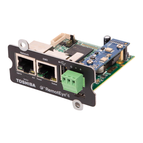
on G9000 Series UPS (Pre-Installed Brackets)
This kit contains the parts to neatly and securely attach the RemotEye 4 network monitoring card
(Part # T90RMTI4-NB) to the inside door of all G9000 UPSs. This document covers attaching the
device with the hardware kit only; for wiring and programming instructions, refer to the RemotEye 4
User Manual (Document #90988).
Important Note: this Guide is for RemotEye 4 installations on G9000 units shipped after February
th
14
, 2017. Please use Part # T90RMTI4 and reference the previous revision of this manual (#90000-
002) for any units shipped before this date.
1.0 Contents
Instructions for G9000 Series UPS RemotEye – 90000-004
Procedure for Installing the RemotEye
Table 1 RemotEye 4 Installation Kit Contents
No.
1
RemotEye 4 Card w/ Box
93805 – RemotEye 4 Comm Cable
2
65816 – RemotEye 4 PCB Mounting Box
3
4
Accessory Pack (Details Below)
4.1
Standoff, M3 x 15mm
4.2
Screw, M3 x 12mm
4.3
Screw, 6/32 x 3/8in.
4.4
Zip Tie
Kit Contents
Item
Part No. 90000-004
Date: February 2020
®
4
Qty.
1
1
1
1
2
2
4
5
Page 1 of 8
Advertisement

Related Manuals for Toshiba RemotEye 4


Summary of Contents for Toshiba RemotEye 4
- Page 1 Procedure for Installing the RemotEye on G9000 Series UPS (Pre-Installed Brackets) This kit contains the parts to neatly and securely attach the RemotEye 4 network monitoring card (Part # T90RMTI4-NB) to the inside door of all G9000 UPSs. This document covers attaching the device with the hardware kit only;...
- Page 2 Figure 1: RemotEye 4 PCB Mounting Box #65816 Figure 2: RemotEye 4 Comm Cable #93805 Figure 3: Accessory Pack Mounting Hardware: 2 – Standoffs, M3 x 15mm 2 – Screw, M3 x 12mm 4 – Screw, 6/32 x 3/8” 5 – Zip Tie Instructions for G9000 Series UPS RemotEye –...
- Page 3 2.2 Open the G9000’s door, and remove the dead front cover (if any) covering the display PCBs on the inside of the door. 2.3 Reference Figure 4 through Figure 9 to determine the specific location of the RemotEye 4 mounting location as well as the mounting holes for the ribbon cable bracket (shown within the red ellipse).
- Page 4 Figure 6: 300kVA RemotEye 4 Location Figure 7: 500kVA RemotEye 4 Location Instructions for G9000 Series UPS RemotEye – 90000-004 Page 4 of 8...
- Page 5 Figure 8: 750kVA RemotEye 4 Location Figure 9: 1000kVA RemotEye 4 Location Instructions for G9000 Series UPS RemotEye – 90000-004 Page 5 of 8...
- Page 6 3.0 INSTALL REMOTEYE 4 This step provides instructions for mounting and connecting the RemotEye 4 in the G9000 Series UPS. NOTE: Numbered components in Figures 11-13 correspond to the numbered entries of the Kit Contents Table on Page 1. 3.1 Orient the PCB Mounting Box, Figure 11-(3) so the back connector is on the same side as the RemotEye 4 Mounting Bracket angle and press the mounting box into the mounting bracket until the retaining tabs, Figure 11-(3T), engage.
- Page 7 Secure the wiring with the provided cable ties or equivalent as shown in Figures 11, 12 & 13-(4.4) This completes the hardware installation of the RemotEye 4. Complete the setup of the RemotEye 4 per the RemotEye 4 User’s Manual, P/N 90988.
- Page 8 PSAU-60 Figure 13: Install RemotEye 4 Cabling (500kVA) Instructions for G9000 Series UPS RemotEye – 90000-004 Page 8 of 8...