
Related Manuals for Gendex ORTHORALIX 9200


Summary of Contents for Gendex ORTHORALIX 9200
- Page 1 Printed on: 20 Apr 2012, 04:59:40 pm; Printed by: UWE.ZELLER ©2009 Gendex Dental Systems, 4519-190-71193 Rev 7...
-
Page 2: Table Of Contents
Screen lm sensibility selection A-10 ........A.4.3 Rotating unit ....................A.5.4.18 Service programs A-10 ................. A.4.4 Tubehead ......................A.5.4.19 Orthoralix 9200 CCD sensor A-10 ..........A.4.5 Patient head rest ................... A.5.4.20 Laser projectors A-10 ................A.4.6 Ceph arm ......................A.5.5... -
Page 3: Introduction
In particular the radiation intensity is measured by an appropriate X-ray sensor during examination (For the Orthoralix 9200 DDE versions only one TMJ lateral projec- and, depending from the kind of projection, the system modu- tion is available). -
Page 4: Motorised Column
Disabled Disabled RIGHT JAW Enabled Disabled The Orthoralix 9200 DDE is a version of the Orthoralix 9200 fa- mily providing real-time digital image acquisition using a digital LEFT JAW Enabled Disabled CCD sensor interconnected to a personal computer using an... -
Page 5: System Versions
Orthoralix 9200 DDE (USA - with ceph sensor) 5105 0221WW Orthoralix 9200 DDE (ROW - with ceph sensor) 5105 0231US Orthoralix 9200 DDE Plus (USA - with ceph sensor) 5105 0231WW Orthoralix 9200 DDE Plus (ROW - with ceph sensor) 5105 0241WW... -
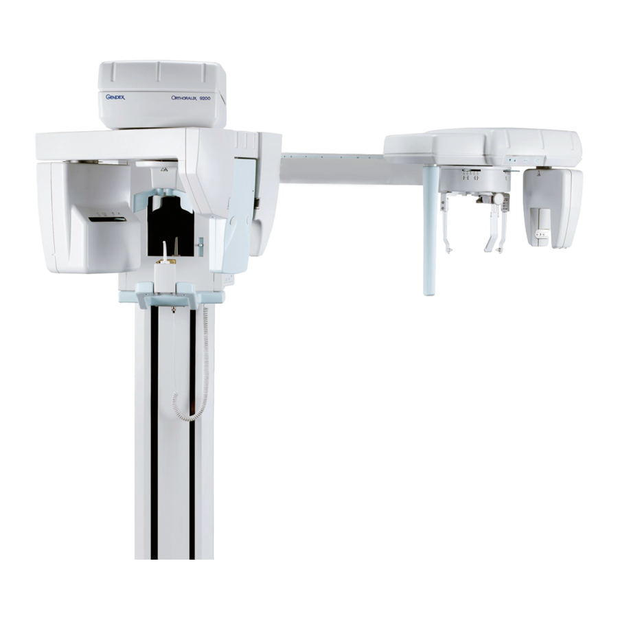
Page 6: System Identi Cation
ORTHORALIX 9200 Service Manual A.4.3 Rotating unit System identification The rotating unit is suspended from the Z-carriage. It carries: For system identification please refer to the technical label at A-14. the tubehead the cassette drive system with the relevant gear motor System components the panoramic digital sensor (DDE versions only). -
Page 7: Remote Control Box
Preparing the installation site In the DDE versions, the X-ray beams are shielded by the sensor Orthoralix 9200 is to be mounted on a normal masonry wall. assembly, introducing a filtration equivalent to 1.5 mm of lead. It takes three men to attach the column to the wall and to mount the Z-carriage to the column. -
Page 8: Electrical Data
ORTHORALIX 9200 Service Manual A.5.3 Electrical data A.5.3.4 Mains frequency The mains frequency required is 50 or 60 Hz, with excursion within A.5.3.1 Mains requirements the 48 to 62 Hz acceptable range. The equipment must be permanently connected to the mains. -
Page 9: Performance Data
ORTHORALIX 9200 Service Manual A.5.4 Performance data A.5.4.4 X-ray tube Tube type: GX 100-20 DC A.5.4.1 Exposure geometry data (Pan mode) Focal spot size: 0.5 (IEC 336/1993) Distance from focal spot to mechanical rotational centre: 350 mm Anode angle: 5°... -
Page 10: Tube Voltage
ORTHORALIX 9200 Service Manual A.5.4.8 Tube voltage A.5.4.12 Anatomical programs The kV range is 60-84 kV, with steps of 2 kV. Both for Pan and Ceph operation modes several sets of pre-pro- grammed exposure factors are available, selected by patient size... -
Page 11: Exposure Control
ORTHORALIX 9200 Service Manual A.5.4.18 Service programs A.5.4.15 Exposure control The Orthoralix system incorporates diagnostic service software There is a single step exposure handswitch which commands the programs, which can be run either by the operator for a routine rotation start (Pan modes only) and the X-ray exposure. -
Page 12: Dimensions And Weights
ORTHORALIX 9200 Service Manual A.5.5 Dimensions and weights A.5.6 IEC Classification The equipment is packed in three wooden crates containing all parts and accessories. a) for Orthoralix 9200/Plus/Ceph against ingress of liquids) Crate (1) Column and counterweights: aesthetics and/or flammable cleaning agents are present. -
Page 13: Intensifying Screens
ORTHORALIX 9200 Service Manual A.5.10 Intensifying screens A.5.12 Environmental data The available intensifying screens are: The Orthoralix system complies with the following environmental classifications: TYPE NUMBER APPLICATION DIMENSIONS set of 2 screens 15x30 emergency rooms. cm, green emitting,rare 9869 007 10501 earth, type Kodak Lanex shock levels. -
Page 14: Dimensions
ORTHORALIX 9200 Service Manual Dimensions A-13 Gendex Dental Systems 4519-190-71193-7 (03.0)E Printed on: 20 Apr 2012, 04:59:40 pm; Printed by: UWE.ZELLER... - Page 15 TYPE B FIRE AND MECHANICAL HAZARDS ONLY IN ACCORDANCE WITH IEC 60601-1 CERTIFICATION Product complies with radiation performance Gendex Dental Systems, Des Plaines, IL USA standards under the Federal Food, Drug, and Cosmetic Act, and meets requirements of IEC 60601-1. 0086...
- Page 16 TYPE B FIRE AND MECHANICAL HAZARDS ONLY IN ACCORDANCE WITH IEC 60601-1 CERTIFICATION Product complies with radiation performance Gendex Dental Systems, Des Plaines, IL USA standards under the Federal Food, Drug, and Cosmetic Act, and meets requirements of IEC 60601-1. 0086...
-
Page 17: Cooling Data
ORTHORALIX 9200 Service Manual Cooling data A-16 Gendex Dental Systems 4519-190-71193-7 (03.0)E (03.0)E Printed on: 20 Apr 2012, 04:59:40 pm; Printed by: UWE.ZELLER... - Page 18 Installation Table of contents B.5.10 Mounting the z-carriage covers ........B-16 B.1 Introduction ..............B-2 B.5.11 Creating a network connection for the Orthoralix 9200 ... B.2 Installation tools ..............B-2 B-17 B.5.11.1 Orthoralix 9200 DDE/Ceph ........B-17 B.3 Supply ................B-2 B.5.12 Mounting the column covers and the quick reference B.3.1...
-
Page 19: Introduction
ORTHORALIX 9200 Service Manual B.4.2 Space required Introduction For the dimensions of the various system versions see A-13. This section provides details about the installation of the Ortho- B.4.3 Room preparation ralix Panoramic and CEPH systems. The system is designed to be fixed to the wall by means of six bolts. -
Page 20: Electrical Pre-Installation
ORTHORALIX 9200 Service Manual B.4.4 Electrical pre-installation Wall The Orthoralix requires a fixed electrical installation. The mains cable required is two poles with ground (not sup- plied). The mains cable inlet is at the rear of the column, and is provided with cable retainer. -
Page 21: Mechanical Installation
ORTHORALIX 9200 Service Manual Mechanical installation B.5.1 Unpacking Open the two crates (three for the CEPH versions) and check the contents as specified in the CHECK LIST B-29. The unit has been adjusted and tested in our factory to reduce installation time. -
Page 22: Installing The Column On The Wall
ORTHORALIX 9200 Service Manual B.5.2 Installing the column on the wall To take out the column from the crate and transport it on the desired installation site, two ropes are provided. Use adeguate gloves to protect the hand. The column is heavier than 20 kg and so during the installation it must be handled with care by three men, avoiding any risk of injury. - Page 23 ORTHORALIX 9200 Service Manual Case B: With bracket, not concrete walls. Case A: Without bracket, concrete/brick walls. Fix the wall plate (a) to the top of the column by means of Mark the six fixation points on the wall, having checked that four screws and fix the wall plate (b) to the bottom of the the column is level.
- Page 24 Ceph arm crate) through the hole provided in the top left column side. Orthoralix 9200 DDE Ceph only: In the DDE Ceph arm crate there are also two additional small counterweights to be inserted in the column.
-
Page 25: Installing The Z-Carriage On To The Column
ORTHORALIX 9200 Service Manual B.5.3 Installing the z-carriage on to the column The Z-carriage is delivered assembled with rotating unit and tubehead and shipped turned upside down. The rotating unit and the Z-carriage are connected by a fixing bracket. The following covers are disassembled in the packing: DDE versions). - Page 26 Z-carriage from the mains supply. Connect the connectors X72A with X72B and X71A with X71B to power the motor of the column. For Orthoralix 9200 DDE only: feed the connector X11 into the Z/Carriage. Gendex Dental Systems 4519-190-71193-7 (03.0)E...
-
Page 27: Installing The Ceph Arm
ORTHORALIX 9200 Service Manual B.5.4 Installing the ceph arm Remove the bracket (a) fixing the rotating unit to the Z-car- riage. B.5.4.1 Procedure for Orthoralix 9200 Turn the rotary unit 90 to allow easier access to the electronic board. To install the ceph arm with Cephalostat follow the procedure... -
Page 28: Procedure For Orthoralix 9200 Dde
Mount the nasion rest (f) into the pin and fix it with knob (g). B.5.4.2 Procedure for Orthoralix 9200 DDE To install the ceph arm with Cephalostat follow the procedure below (applicable only for the CEPH versions):... -
Page 29: Mounting The Front Panel With Mirror
ORTHORALIX 9200 Service Manual Remove the connector X37 from the host computer board Install the toroid supplied with the ceph arm on the wires of PC1 and disconnect the connector connected to the red the connector X8 of the PA7 board. -
Page 30: Mains Voltage Programming
Case A: Single phase mains supply For the connection to the mains proceed as follows: The Orthoralix 9200 system can operate with a nominal mains voltage in the 115 VAC to 250 VAC range. Remove the cover (a) from the column (4 screws). -
Page 31: Checking Mains Polarity
ORTHORALIX 9200 Service Manual B.5.8 Checking mains polarity To check the proper electrical polarity of live and neutral wires, proceed as follows: Connect an AC voltmeter between the live terminal of mains connection points and the protective ground screw. Turn on the room supply and check that the full line voltage is measured: if not, reverse the mains connection points and repeat. -
Page 32: Installing The Remote Control Box
ORTHORALIX 9200 Service Manual B.5.9 Installing the remote control box A remote control box is available for the Orthoralix 9200 system, to be installed on the wall. A 20 m. cable is supplied, to connect the control box to the Z- carriage. -
Page 33: Mounting The Z-Carriage Covers
Before finally mounting the covers it is advisable to com- For the Orthoralix 9200 DDE versions, install the back rear plete the actions described in section C “Setting to work”, cover of the DMU holder (e), by pushing it into the spring where free access to the internal parts of the system may latches provided and by fixing it with the three screws (d). -
Page 34: Creating A Network Connection For The Orthoralix 9200
14. Press the Reset button on the 9200 control panel. Insert the supplied CD-ROM and install the necessary sensor.dat file. An icon for the Orthoralix 9200 will appear in the system tray near the clock on your PC’s desktop. This icon can be used to launch the Orthoralix DDE Setup Screen. - Page 35 12. Press the Reset button on the 9200 control panel. Manager. Turn off the Orthoralix 9200. If you only have one machine to install, please proceed to Step 10. Continue to Step 6 if you have more than one machine to install or already installed.
-
Page 36: Mounting The Column Covers And The Quick Reference Guide
With the system are available two Quick Reference Guide the PC6 board labels, one for the Orthoralix 9200/Plus and the other one for the Orthoralix 9200/Plus/DDE; select the correct one and Mount the bottom front cover (a) of the column by means install it on the right cover of the column, so that the lower of four screws (b). -
Page 37: Installing The Ceph Formats
ORTHORALIX 9200 Service Manual B.5.13 Installing the ceph formats Remove the plate (d) from the collimator by unscrewing the two screws (e). B.5.13.1 Orthoralix 9200/Plus/Ceph The following lead plates supplied with the system allow for dif- ferent Ceph X-rays formats:... -
Page 38: Orthoralix 9200 Dde/Ceph
ORTHORALIX 9200 Service Manual B.5.13.2 Orthoralix 9200 DDE/Ceph Remove the plate (d) from the collimator by unscrewing the two screws (e). Two lead plates are supplied with the system to allow all the fol- lowing Ceph X-rays formats: one lead plate height 18 cm (H 18 written on the lead plate) -
Page 39: Installing The Soft Tissues Lter
X 24 cm. Do not change the position of the adjusting lever during the measurement. In the Orthoralix 9200 DDE Ceph, the soft tissues filter is not present: the filtration for the soft tissues is done during the image acquisition. -
Page 40: Upgrades
ORTHORALIX 9200 Service Manual B.6.3 Field upgrading to the dmf version Upgrades For field upgrading to the DMF (Dento-maxillo facial) version, follow the instructions below. B.6.1 Field upgrading to the ceph version Switch off the system. For field upgrading to the CEPH version refer to the relevant... -
Page 41: Field Upgrading To The "Plus" Version
ORTHORALIX 9200 Service Manual B.6.4 Field upgrading to the “plus” version Options For field upgrading to the PLUS version, follow the instructions below: B.7.1 External lights connection Switch off the system. A kit code 4519 105 20691 is available for external light connection. - Page 42 ORTHORALIX 9200 Service Manual Move down the Z-carriage and remove the top cover (c) by Remove the right lateral column cover (h) by unscrewing the unscrewing the six screws (d). seven screws (i). Do not move the Z-carriage along the column when the system is off:doing so it could damage the PC6 board.
- Page 43 ORTHORALIX 9200 Service Manual Fix the cable (n) on the column by using the cable retiners Connect the cable to the connector X33 of the PC1 board: (o) and (p) supplied. X33-1 RED WIRE X33-2 BLACK WIRE X33-3 WHITE WIRE...
-
Page 44: Column Wall Xation
ORTHORALIX 9200 Service Manual Column wall fixation B-27 Gendex Dental Systems 4519-190-71193-7 (06.0)E (03.0)E Printed on: 20 Apr 2012, 04:59:40 pm; Printed by: UWE.ZELLER... -
Page 45: Check List
ORTHORALIX 9200 Service Manual Ceph arm Check list Assy nasion The following parts are included in the delivery: Ear plugs Hygienic bags for ear plug Column Counterweight Counterweight Additional counterweight (DDE versions only) Bolts for wall fixation Soft tissue filter (not for DDE versions) -
Page 46: Grounding Connection
Grounding Connection to AC Service in Patient Care Area The following method shall be used to ground AC Service to the Orthoralix 9200 in patient care areas. These instructions supplement the installation instructions provided in the Orthoralix 9200 Service Manual, Section B. - Page 47 ORTHORALIX 9200 Service Manual 3. Ground AC service to L-bracket using an electrician supplied 5. Terminate the conductors in the terminal strip and strain tting listed for grounding, or other approved method in relief using the cable clamp located below the terminal strip accordance with the local electrical code (see Figure 2).
- Page 48 ............... C.5 Adjustments and checks ............... C.5.1 Alignment of x-ray eld pan mode ..........C.5.1.1 Orthoralix 9200/Plus/Ceph ............C.5.1.2 Orthoralix 9200 DDE ..............C.5.2 Alignment of x-ray eld transcan mode ........C.5.2.1 Orthoralix 9200/Plus/Ceph ............C.5.2.2 Orthoralix 9200 DDE ..............
- Page 49 Dummy run Centering laser lights ON A.E.C. Ready for exposure Exposure ON Pan selected Ceph selected Transcan selected Small patient Medium patient Column up Column down Gendex Dental Systems 4519-190-71193-7 Printed on: 20 Apr 2012, 04:59:40 pm; Printed by: UWE.ZELLER...
- Page 50 WAIT 2 min 0.80 Film B Good Wrong Wrong Wrong Wrong The vertical dimension of the X-ray field measured on a panoramic film is 131mm ± 3mm. Gendex Dental Systems 4519-190-71193-7 Printed on: 20 Apr 2012, 04:59:40 pm; Printed by: UWE.ZELLER...
- Page 51 Select the panoramic position on the collimator and on the operator panel. Switch on the PC where the Orthoralix 9200 DDE is connected The grey sections may help in understanding the correct or wrong aligment and how much the lead plate must be adjusted.
- Page 52 Film B Left Right Not vertical Film A ary slit as shown in the figure. Film B Film A Good Film B S e - lect the Gendex Dental Systems 4519-190-71193-7 Printed on: 20 Apr 2012, 04:59:40 pm; Printed by: UWE.ZELLER...
- Page 53 X-ray field respect to the digital sensor. Select the transcan position on the collimator and on the operator panel. Switch on the PC where the Orthoralix 9200 DDE is connected paragraph Adjusting the X-ray collimator of the Section F four options will be displayed: Stop and then on Static image.
- Page 54 Service Manual, to compare the film to be exposed into it. results obtained in the field. Orthoralix 9200 DDE zontal line “d”. Check that line “d” is horizontal and flat within a band of 6 mm.
- Page 55 Service Manual C.5.4.2 Orthoralix 9200 DDE Make an exposure by using the minimum exposure param- steps: program. alignment of the ceph secondary collimator respect to the DMU. C.5.4 Alignment of X-ray field ceph mode respect to the ceph secondary collimator.
- Page 56 Section F: Adjustment of the light projectors. mid-sagittal projector as described in Section F: Adjustment of the light projectors. Mid sagittal Horizontal Gendex Dental Systems 4519-190-71193-7 Printed on: 20 Apr 2012, 04:59:40 pm; Printed by: UWE.ZELLER...
- Page 57 X-rays and by the “dead-man” function. and “TUBEHEAD” operator alarms described in section F. C.6.2 Customer test standards perform the tests described in section D: Acceptance. C-10 Gendex Dental Systems 4519-190-71193-7 Printed on: 20 Apr 2012, 04:59:40 pm; Printed by: UWE.ZELLER...
- Page 58 Service Manual Configuration chart DEFAULT VALUE NEW VALUE CALIBRATION VALUE 80 kV limit: FRANCAIS DEUTSCH PANORAMIC CEPH DATE AEC Pan Tune AEC Ceph Tune C-11 Gendex Dental Systems 4519-190-71193-7 Printed on: 20 Apr 2012, 04:59:40 pm; Printed by: UWE.ZELLER...
- Page 59 Service Manual MEDIUM PATIENT PANORAMIC RR POSTERIOR 3 mm RR POSTERIOR 6 mm RR INCISOR 3 mm RR INCISOR 6 mm CEPH AP/PA C-12 Gendex Dental Systems 4519-190-71193-7 Printed on: 20 Apr 2012, 04:59:40 pm; Printed by: UWE.ZELLER...
- Page 60 Standards compliance tests ....................D.4 Acceptance checklist ............... Check that the Certification, Identification, Place and Date of label on the column comply with the specifications. Gendex Dental Systems 4519-190-71193-7 (03.0)E Printed on: 20 Apr 2012, 04:59:40 pm; Printed by: UWE.ZELLER...
- Page 61 ORTHORALIX 9200 Service Manual D.3.2 Tube current accuracy MAX kV MODULATION RESPECT TO PROJECTION THE SELECTED VALUE - 6 % CHILD - 7 % - 8 % The tube current accuracy is ± 7% (the accuracy of the instrument RIGHT JAW -10 % used for the measurement is excluded).
- Page 62 ORTHORALIX 9200 Service Manual To measure exposure time, a timer counter can be used connected tubehead and collimator are lower than 250 µGy/h (28 mR/h) as specified. basic accuracy for exposure time measurement of the radiation monitor must be considered.
- Page 63 ORTHORALIX 9200 Service Manual Acceptance checklist R / S ACTION MEASUREMENTS REMARKS 1. General inspection 3.2. Tube current accuracy 3.3. kV pk accuracy 3.4. Timer accuracy 3.5. Radiation dose rate 3.6. Reproducibility 3.8. Earth resistance DATE Gendex Dental Systems 4519-190-71193-7 (03.0)E...
- Page 64 ..............Do not move the Z-carriage along the column when the system is off. Doing so it could damage the PC6 board. Requirements Cleaning materials: Lubricants: Gendex Dental Systems (03.0)E Printed on: 20 Apr 2012, 04:59:40 pm; Printed by: UWE.ZELLER...
- Page 65 Service Manual Clean the whole system. Clean the roller guide along the column. Remove the following covers: motors using spray grease. Grease the following parts Checking the two steel cables the rotation hub ceph arm It is essential to check, clean, lubricate and replace 10.000 (latest 96 months) the steel cables to guarantee the cycles 7.
- Page 66 Service Manual NOMINAL VALUE (kV) FEEDBACK ACCEPTANCE Electrical checks TP13 SETPOINT TP18 RANGE (V) 5.70 Tests 5.7 to 5.12 are intended for standard compliance certification. Check the anodic current (setpoint, feedback, wave- form) on converter board PQ1 (0V reference at TP 20). 7.10 7.30 NOMINAL VALUE ( V )
- Page 67 Service Manual Check the exposure time. The exposure time can be measured with the oscil- loscope using the solar cell or monitoring the mA be calculated when the signal reaches 25 % of the maximum value (raising and falling edges); toler- ance: 20 ms or ±...
- Page 68 Service Manual SELECTED TIME ( s ) MEASURED TIME ( s ) E.7.1 Verify the anodic current NOMINAL VALUE (V) MEASURED VALUE (V) 2.50 1.57 12 (Standard Panoramic) E.7.5 Verify the reproducibility MEASURED DOSE EXPOSURE N° R / MIN Gy / s 7.33 E.7.2 Verify the kv...
- Page 69 Printed on: 20 Apr 2012, 04:59:40 pm; Printed by: UWE.ZELLER...
- Page 70 ................F.3.58 HW fault 181 F-21 F.8 Converter inputs read F-73 ..................................F.3.59 HW fault 200 F-21 F.9 PH3 Inputs read F-74 ....................................Gendex Dental Systems 4519-190-71193-7 (04.0)E Printed on: 20 Apr 2012, 04:59:40 pm; Printed by: UWE.ZELLER...
- Page 71 If the converter board PQ1 or the tubehead need to be replaced, the service programs Tube calibra- While the Orthoralix 9200 system is running, a number of mes- tion and Vf tube editing must be performed (see sages may be generated on the display, to warn the operator...
- Page 72 ORTHORALIX 9200 Service Manual Check whether the LED H11 is ON (ON=OK, OFF=NOT OK). F.3.3 Operator released Possible causes: This alarm message appears on the display when the X-ray com- mand has been released during a working cycle but out of the ambient temperature too high X-ray phase (i.e.
- Page 73 ORTHORALIX 9200 Service Manual F.3.4 Movement halted F.3.6 Handswitch error This alarm message appears on the display when the reset cycle This alarm appears on the display in the following conditions: has been stopped by pressing the DUMMY RUN pushbutton on...
- Page 74 ORTHORALIX 9200 Service Manual F.3.8 Fault opto film F.3.10 Tubehead This alarm message is always related to the optoswitch S16 that The position of the tubehead is detected by two optoswitches (S19 for the teleradiographic position and S20 for the panoramic/...
- Page 75 ORTHORALIX 9200 Service Manual F.3.11 Optoswitches collimator fail F.3.12 Optoswitches tubehead fail Three optoswitches (S21, S22 and S30) are mounted on the col- The position of the tubehead is detected by two optoswitches limator to detect the different positions selected, as listed in the...
- Page 76 ORTHORALIX 9200 Service Manual F.3.13 Secondary slider The host provides a diagnostic message on the display and waits for the alarm to self-reset before starting a new exposure Two optoswitches (S31 and S32) are mounted on the panoramic sequence. cassette carriage to detect the position of the secondary slit,...
- Page 77 ORTHORALIX 9200 Service Manual F.3.16 +5V conv. alarm Check the reference voltage of the A/D converter (+5V) on TP19 and TP8 (GND): adjust if necessary by acting on potentiometer P1 (is mandatory to use an high resolution, 4digits multime- ance ± 10 %).
- Page 78 ORTHORALIX 9200 Service Manual F.3.19 +14V under range F.3.20 +14V over range The system control board PC1 +14V power supply is out of range, The system control board PC1 +14V power supply is out of range, less than 12V (if it is less than 10V, the system control board is over than 16V.
- Page 79 ORTHORALIX 9200 Service Manual F.3.21 +42V under range F.3.22 +42V over range The system control board PC1 +42V power supply is under range. The system control board PC1 +42V power supply is over range. This power supply is coming from the PFC board PN1 and it is con- This power supply is coming from the PFC board PN1 and it is con- trolled by the microprocessor of the system control board PC1.
- Page 80 ORTHORALIX 9200 Service Manual F.3.23 kV out of range F.3.24 mA out of range The kV feedback from the tubehead is monitored by a comparator The mA feedback coming from the tubehead is monitored by a connected to the interrupt line of the microcontroller.
- Page 81 ORTHORALIX 9200 Service Manual F.3.25 I CHP out range F.3.27 CHP. over current The current passing through the power transistors mounted on The current passing through the power transistors mounted on to the microcontroller of the converter board itself. to the microcontroller of the converter board itself.
- Page 82 ORTHORALIX 9200 Service Manual F.3.29 Back up timer F.3.30 No Start/Stop HW The back-up time is counted by the microcontroller mounted on The microprocessor of the PC1 system control board is sending the X-ray on start signals (one is a digital signal, the other one is...
- Page 83 ORTHORALIX 9200 Service Manual F.3.31 Reset -X- failed F.3.32 Reset -Y- failed Every movement (X,Y, R and C) has a maximum time (about 20 s) Every movement (X,Y, R and C) has a maximum time (about 20 s) to reach the reset position after pressing the RESET pushbutton to reach the reset position after pressing the RESET pushbutton on the control panel.
- Page 84 ORTHORALIX 9200 Service Manual F.3.34 Reset -C- failed F.3.33 Reset -R- failed Every movement (X,Y, R and C) has a maximum time (about 20 s) Every movement (X,Y, R and C) has a maximum time (about 20 s) to reach the reset position after pressing the RESET pushbutton to reach the reset position after pressing the RESET pushbutton on the control panel.
- Page 85 ORTHORALIX 9200 Service Manual F.3.35 Console: link failure F.3.37 Conv.link fail 2 The host computer board PC1 has detected a protocol error in the communication with the operator console control board PC7: as munication with the host computer board PC1: as soon the cor-...
- Page 86 ORTHORALIX 9200 Service Manual F.3.39 PA5 board link failure F.3.40 PH3 Ceph alarm The host computer board PC1 has detected a protocol error in The host computer board PC1 has detected a protocol error in the the communication with the PA5 AEC control board.
- Page 87 ORTHORALIX 9200 Service Manual If the host computer PC1 needs to be replaced, re- F.3.43 Software error member to remove the EEPROM D38 from the old The microprocessor of the PC1 system control board is checking board and mount it on the new one, otherwise all...
- Page 88 ORTHORALIX 9200 Service Manual F.3.47 DMU misplaced F.3.49 DMU not ready This alarm message appears when the DMU is in the panoramic This message appears on the display when the system is switched position and the collimator is in one of the ceph positions.
- Page 89 ORTHORALIX 9200 Service Manual F.3.52 DMU fault cables X8 and/or X6 not connected properly on the auxiliary board PA7 This message appears on the display when in the auxiliary board connectors X8 and/or X6 broken on the auxiliary board PA7 the electronic part controlling the communication with the DMU is not able to communicate with the DMU.
- Page 90 This alarm message is generated when in the menu Config (en- communication bus of the auxiliary board PA7. abled by clicking on the Orthoralix 9200 DDE icon in the system tray of Windows) is not done the correct configuration: Press the RESET pushbutton on the control panel to cancel the alarm.
- Page 91 ORTHORALIX 9200 Service Manual Service programs ments : - X = start position of the X movement - Y = start position of the Y movement F.4.1 General - RAB = start position of the rotation movement The Orthoralix system incorporates diagnostic service software...
- Page 92 ORTHORALIX 9200 Service Manual where: The following message will appear on the display: -R- TEST & ADJ. with respect to the reset position +0 +0 XYRABC where: start position of the movement ment with respect to the reset position - the second number...
- Page 93 C movement test and adjustment Modify the movement start position. With this procedure you can modify the start position of the A) For Orthoralix 9200 /Plus /Ceph versions: movement via software, instead of by changing the actuator of the relevant optoswitch.
- Page 94 By selecting this service program it is possible to check and to The correspondence between the number displayed and change the Subnet Mask address of the Orthoralix 9200 DDE when the shift in mm is the following: it is connected to the LAN network. The Subnet Mask address is made of four numbers, having a range from 0 to 255.
- Page 95 ORTHORALIX 9200 Service Manual F.4.3.7 Host input read Suggestions: The status of the optoswitches can be: hardware inputs of the host computer board PC1, with four nW= wide collimator selected hexadecimal numbers. Nw= narrow collimator selected In this way you can check whether the host computer board...
- Page 96 F.4.3.11 Pan and Ceph PH3 input read the number after HP indicates the software version of the This service program is applicable only for Orthoralix 9200 DDE Panoramic DMU Interface board PH3 versions. the number after HC indicates the software version of the Ceph DMU Interface board PH3.
- Page 97 F.4.3.20 Free exposure off. This service program is not applicable for Orthoralix 9200 DDE F.4.3.18 X-ray alignment versions. This service program is applicable only for Orthoralix 9200 DDE With this program you can have an X-ray emission with the param- versions.
- Page 98 ORTHORALIX 9200 Service Manual F.4.3.22 Still transcan F.4.3.24 Vf tube editing With this program you can have an X-ray emission with the pa- With this program you can modify the parameters for the tube rameters of the transcan technique, without having rotation; the calibration stored in the EEPROM.
- Page 99 ORTHORALIX 9200 Service Manual F.4.3.25 Tube calibration The first part of the test is a check on every key of the keyboard: when a key is pressed, the relevant LED indicator (if present) With this service program you can perform the tube calibration...
- Page 100 ORTHORALIX 9200 Service Manual By pressing the DUMMY RUN key on the keyboard, the following The panoramic AEC sensor and cassette are already calibrated in message will appear: factory, so the calibration parameter is already stored: RETRY READOUT please record this calibration parameter in the Configuration Chart of the Section C of this Service Manual.
- Page 101 ORTHORALIX 9200 Service Manual To modify the calibration parameter, use the Progam +/Program F.4.3.31 Default EEPROM - keys on the keyboard (possible range from -200 to +50) and press With this service program you can reset the information held in...
- Page 102 ORTHORALIX 9200 Service Manual Remove the front panel with mirror (f) by unscrewing the Replacement procedures two screws (g) and disconnect the centering lights connector X31 from the PC1 control board. F.5.1 Replacing multipole cable For the replacement of the multipole cable follow the procedure...
- Page 103 ORTHORALIX 9200 Service Manual Remove the plastic disk (n) by unscrewing the six screws (o) Loosen the two screws (u) of the cable retainer (v). and then remove the three plastic rings (p). Remove all the necessary cable retainers of the multipole cable;...
- Page 104 ORTHORALIX 9200 Service Manual F.5.2 Replacing converter cable Remove the metallic protection (f) of the PN1 board by For the replacement of the converter cable follow the procedure below: Before starting the replacement of the converter cable, be sure that no dangerous voltages are present.
- Page 105 ORTHORALIX 9200 Service Manual Remove the plastic disk (n) by unscrewing the six screws (o) Remove all the necessary cable retainers of the converter and then remove the three plastic rings (p). cable and remove the converter cable itself. Take the new converter cable, lay it down near the old one and sign on it the same reference marks placed on the old one.
- Page 106 ORTHORALIX 9200 Service Manual F.5.3 Replacing the steel ropes Remove the top cover (p) with the pulleys from the col- umn. For the replacement of the steel ropes, proceed as follows: Screw the M6 screw (q) (supplied with the new steel cables) Switch on the system.
- Page 107 ORTHORALIX 9200 Service Manual F.5.4 Replacing optoswitches Type 2 Looking at the optoswitch from the front it is possible to see that Two types of optoswitches could be mounted in the system: one part is grey and the other one is black.
- Page 108 ORTHORALIX 9200 Service Manual F.5.5 Replacing the drive belts The belts for all the movements (X, Y, R and Cassette) are the same, only the length is different; as spare part, a belt 1 meter long is supplied: it is a task of the service engineer to cut the belt at the right length, comparing the new one with the old one.
- Page 109 ORTHORALIX 9200 Service Manual For the replacement of the Y drive belt proceed as follows: Loosen the belt stretcher by unscrewing the nut (a) and then bolt (b). Remove the screws (c) with plates and replace the belt (d). Ensure that the plates are properly accommodated on the teeth of the new belt, then fix them with securing screws (c).
- Page 110 ORTHORALIX 9200 Service Manual For the replacement of the R drive belt proceed as follows: Loosen the dowel (a) and by turning the eccentric (b) with an open wrench reduce the tension of the belt. Remove the screws (c) with plates and replace the belt (d).
- Page 111 ORTHORALIX 9200 Service Manual For the replacement of the Cassette drive belt proceed as fol- lows: Remove the screws (a) with plates and replace the belt (b), taking care that when the belt is unlocked, the roller (c) of the tension mechanism may fall down.
- Page 112 ORTHORALIX 9200 Service Manual In the ceph arm for the Orthoralix 9200 DDE versions, others three C) Belt from the motor to the ceph secondary collimator belts (used to move the ceph secondary collimator and the Digital movement Module Unit DMU) are present.
- Page 113 ORTHORALIX 9200 Service Manual F.5.6 Replacing the tubehead Remove the collimator assembly from the tubehead, by unscrewing the four screws (g). For the replacement of the tubehead proceed as follows: Remove the front cover (a) of the tubehead by unscrewing two screws (b) and by disengaging the spring latches from the rear cover (c).
- Page 114 ORTHORALIX 9200 Service Manual F.5.7 Replacing the PC1 control board During the mounting of the new tubehead, please take note of the following: A) For Orthoralix 9200/Plus/Ceph nections on the terminal block 600 To replace the PC1 control board, proceed as follows:...
- Page 115 PC1 on the metallic plate by means of the five screws. restore all the connections to the new PC1. B) For Orthoralix 9200 DDE/Ceph To replace the PC1 control board, proceed as follows: remove the mirror panel (a) by unscrewing the two Allen screws (b).
- Page 116 ORTHORALIX 9200 Service Manual replace the EEPROM D38 on the new PC1 with the one re- moved from the old PC1. take the two integrated circuits D33 and D37 previously re- moved from the old PC1 and mount them on the new PC1 into the sockets D33 and D37 indifferently.
- Page 117 ORTHORALIX 9200 Service Manual F.5.9 Replacing the PN1 power unit board To replace the PN1 board, proceed as follows: Disconnect the system from the mains supply. Remove the top cover (a) of the Z-carriage by unscrewing the six screws (b).
- Page 118 ORTHORALIX 9200 Service Manual F.5.10 Replacing the PA5 aec control board F.5.11 Replacing the PH3 unit interface board After the replacement of the PA5 AEC control board, follow the After the replacement of the PH3 unit interface board, it is nec-...
- Page 119 ORTHORALIX 9200 Service Manual Take note that in case of a big error in the simmetry, even the Adjustment procedures central vertical line “a” could be not vertical with respect to the ment, also this problem will be solved. F.6.1...
- Page 120 ORTHORALIX 9200 Service Manual Take note that in case of a big error in the position of the dark If the image is too wide, introduce negative correction number area, even the central vertical line “a” could be not vertical with by pressing the key s- on the operator panel (max -99).
- Page 121 ORTHORALIX 9200 Service Manual F.6.2 Tension adjustment of the drive belts For the tension adjustment of the drive belts, proceed as follows: Remove the top cover (a) of the Z-carriage by unscrewing the six Allen screws (b). If it is necessary to adjust the tension of the rotation belt, remove also the lower cover (c) and the central cover (d), by removing the four screws (e).
- Page 122 Orthoralix 9200 DDE Ceph only For the tension adjustment of the drive belts in ceph arm of the Orthoralix 9200 DDE, proceed as follows: for the belt (a) (from the motor to the DMU (Digital Module Unit), unlock the nut (b) of the belt stretcher and turn the bolt (c).
- Page 123 ORTHORALIX 9200 Service Manual F.6.3 Adjusting the x-ray collimator Adjustment of the ceph lead plates. The X-ray fields in ceph mode (for the different formats (A) Orthoralix 9200/Plus/Ceph a distance of about 7 mm from the film edges : to do this,...
- Page 124 ORTHORALIX 9200 Service Manual B) Orthoralix 9200 DDE/Ceph Switch on the PC where the Orthoralix 9200 DDE is connected The X-ray collimator is moveable, with four selectable positions: Access to the DDE icon in the system tray: when on it, with the cursor of the mouse, click with the right mouse pushbutton;...
- Page 125 ORTHORALIX 9200 Service Manual Ceph adjustment In this case the alignment procedure is divided in two steps: of the leads support plate (e) (1 mm of shift of the plate is alignment of the ceph secondary collimator respect to the corresponding to 3 mm on the secondary slit).
- Page 126 DMU in the middle of the ceph projec- tion. Switch on the PC where the Orthoralix 9200 DDE is connected Access to the DDE icon in the system tray: when on it, with the cursor of the mouse, click with the right mouse pushbutton;...
- Page 127 ORTHORALIX 9200 Service Manual four Allen screws (a) in the ceph arm and move the ceph ary collimator, the alarm Ceph collimator appears secondary collimator assembly (b) in the desired direction. on the display, see Step (2) point (14). If the X-ray field shall be vertically adjusted, remove first the...
- Page 128 ORTHORALIX 9200 Service Manual After the adjustment, make another exposure to check the Now, make an exposure; after the preview, the following will result: to do it, click first on Stop and then click on Static im- appear on the monitor: age.
- Page 129 ORTHORALIX 9200 Service Manual If the X-ray field shall be vertically adjusted, unlock the two Switch off the system to exit the Service Programs. crews (e) and move the lead plate (f) in the vertical desired Switch on the system.
- Page 130 ORTHORALIX 9200 Service Manual F.6.4 Adjusting the light projectors (c) by unscrewing two Allen screws (d). Disconnect the connector X31 from the PC1 control board. the eyes directly to the laser beam. Make sure that the system is in the reset position.
- Page 131 ORTHORALIX 9200 Service Manual To adjust the mid-sagittal vertical light projector, proceed as If not, remove the mirror panel (c) by unscrewing two Allen follows: screws (d). Make sure that the system is in the reset position. Disconnect the connector X31 from the PC1 control board.
- Page 132 ORTHORALIX 9200 Service Manual To adjust the lateral vertical light projector, proceed as follows: If not, remove the cover (d) of the light projector by un- screwing three screws (c), accessible from the rear side of For Orthoralix 9200/Plus the panoramic cassette carriage.
- Page 133 ORTHORALIX 9200 Service Manual For Orthoralix 9200 DDE/Ceph If not, remove the cover (a) by removing the three screws (b) and then pull it out to disengage from the spring latches. Make sure that the system is in the reset position.
- Page 134 ORTHORALIX 9200 Service Manual F.6.5 Adjusting patient headrest (PAN) Using a plumb line, verify that the middle position of the headrest assembly is aligned with the middle position of the bite block (see reference middle line on the bite block itself and the figure below).
- Page 135 ORTHORALIX 9200 Service Manual F.6.6 Adjusting patient headrest (CEPH) Insert a cassette with film and screens. Make an exposure with 62 kV - 0.16 s. To adjust the patient headrest of the ceph cephalostat proceed as follows: Develope the film and verify that the two ear rings (a) are aligned (the smaller depicted ring is closest to the film).
- Page 136 ORTHORALIX 9200 Service Manual F.6.7 Adjusting tube current enter the Tube calibration service program. The following message will appear on the display: TUBE CALIBRATION After a replacement of the converter board PQ1 Press DUMMY RUN to go and of the tubehead, it is mandatory to perform the mA calibration.
- Page 137 ORTHORALIX 9200 Service Manual F.6.8 AEC calibration Check that no cassette is inserted in the panoramic cassette carriage and remount the rear cover of the panoramic cas- The calibration of the AEC must be done in the following situa- sette carriage.
- Page 138 ORTHORALIX 9200 Service Manual Case (B): CEPH AEC calibration Insert the panoramic cassette (with the own intensifying screens installed) in the panoramic cassette carriage. Mount the brass filter (code 4519 122 25571) on the ceph cassette carriage so that it covers the AEC sensor of the PA5 Press the DUMMY RUN key on the keyboard;...
- Page 139 ORTHORALIX 9200 Service Manual Press the DUMMY RUN key on the keyboard; the following Make an exposure, then the following will appear: message appears on the display: SL=XX.X 60kV 0.80s Write these parameters on a piece of paper. Rotate the tubehead in the ceph position and move the Switch off the unit.
- Page 140 ORTHORALIX 9200 Service Manual Legenda: Host inputs read NU = NOT USED S4-2 = dip switch S4-2 on the PC1 board A) Orthoralix 9200 OPTO C = optoswitch used to identify the half run position On the display the following message will appear:...
- Page 141 ORTHORALIX 9200 Service Manual B) Orthoralix 9200 DDE Byte WW On the display the following message will appear: CONDITION HOST INPUTS READ optoswitch Ceph cassette: 1= not inserted, 0= inserted XX YY WW ZZ optoswitch Y: 0= reset, 1= no reset...
- Page 142 ORTHORALIX 9200 Service Manual B) Orthoralix 9200 DDE Converter inputs read On the display the following message will appear: CONV INPUTS READ A) Orthoralix 9200 XY 0 0 22 On the display the following message will appear: where the numbers X and Y may have the following values,...
- Page 143 ORTHORALIX 9200 Service Manual Examples PH3 Inputs read CONDITION On the display the following message will appear: DMU not present with 10 or 0 collimator in pan position PH3 PAN : CEPH READ DMU in pan position with XX YY WW ZZ...
- Page 144 (..) for the series indicated this code number is delivered until the stock level is zero. Column 6 = Series numbers (x) this part only to be used from serial number indicated Gendex Dental Systems 4519-190-71193-7 (06.0)E Printed on: 20 Apr 2012, 04:59:40 pm; Printed by: UWE.ZELLER...
- Page 145 ORTHORALIX 9200 Service Manual Gendex Dental Systems 4519-190-71193-7 (04.0)E Printed on: 20 Apr 2012, 04:59:40 pm; Printed by: UWE.ZELLER...
- Page 146 ORTHORALIX 9200 Service Manual Survey of electrical parts (part 1 of 2) 1- PAGE 2- ITEMS 3- DESCRIPTION 4- TECHNICAL DATA 5- CODE NUMBER 6- From series Z3-2 Emi Filter 4519 101 01405 F1/F2 Fuse D F15A-250V-6,3x32 2422 551 00002...
- Page 147 ORTHORALIX 9200 Service Manual blank Intentionally left Gendex Dental Systems 4519-190-71193-7 Printed on: 20 Apr 2012, 04:59:40 pm; Printed by: UWE.ZELLER...
- Page 148 ORTHORALIX 9200 Service Manual Survey of electrical parts (part 2 of 2) 1- PAGE 2- ITEMS 3- DESCRIPTION 4- TECHNICAL DATA 5- CODE NUMBER 6- From series Z2-1 Mains Relay 4519 190 02051 Z2-1 M1, M2, M3, M4 Geared motor...
- Page 149 ORTHORALIX 9200 Service Manual Gendex Dental Systems 4519-190-71193-7 (04.0)E Printed on: 20 Apr 2012, 04:59:40 pm; Printed by: UWE.ZELLER...
- Page 150 ORTHORALIX 9200 Service Manual Z-Carriage Kinematic assy (part 1 of 3) 1- PAGE 2- ITEMS 3- DESCRIPTION 4- TECHNICAL DATA 5- CODE NUMBER 6- From series Q6-a Z-carriage without tubehead 4519 190 01324 Q6-b M1, M2, M3 Geared motor 4519 190 01901...
- Page 151 ORTHORALIX 9200 Service Manual Z-Carriage Front panel with mirror and centering lights (part 2 of 3) 1- PAGE 2- ITEMS 3- DESCRIPTION 4- TECHNICAL DATA 5- CODE NUMBER 6- From series Q8-a ( Front cover with mirror 4519 124 22332...
- Page 152 ORTHORALIX 9200 Service Manual Z-Carriage Patient positioning tools (part 3 of 3) 1- PAGE 2- ITEMS 3- DESCRIPTION 4- TECHNICAL DATA 5- CODE NUMBER 6- From series Q9-a Bite block GXP 20211 Q9-b ) Chin rest 4519 128 20221 Q9-c...
- Page 153 ORTHORALIX 9200 Service Manual Q-10 Gendex Dental Systems 4519-190-71193-7 (04.0)E Printed on: 20 Apr 2012, 04:59:40 pm; Printed by: UWE.ZELLER...
- Page 154 ORTHORALIX 9200 Service Manual Column 1- PAGE 2- ITEMS 3- DESCRIPTION 4- TECHNICAL DATA 5- CODE NUMBER 6- From series Q10-a Emi lter 4519 101 01404 Q10-b Belt 4519 122 25491 Q10-c End stop bracket 4519 122 24231 Q10-d Rubber bumper...
- Page 155 ORTHORALIX 9200 Service Manual Tubehead with collimator 1- PAGE 2- ITEMS 3- DESCRIPTION 4- TECHNICAL DATA 5- CODE NUMBER 6- From series Q12-a Tubehead assy 4519 190 01131 Q12-b ( Collimator C DDE versions only 4519 124 22341 ( Collimator...
- Page 156 ORTHORALIX 9200 Service Manual Cassette holder 1- PAGE 2- ITEMS 3- DESCRIPTION 4- TECHNICAL DATA 5- CODE NUMBER 6- From series Q13-a Geared motor 4519 190 01901 Q13-b AEC control 4519 101 03803 Without AEC 4519 101 04401 Q13-c End stop cassette...
- Page 157 ORTHORALIX 9200 Service Manual Q-14 Gendex Dental Systems 4519-190-71193-7 (04.0)E Printed on: 20 Apr 2012, 04:59:40 pm; Printed by: UWE.ZELLER...
- Page 158 ORTHORALIX 9200 Service Manual Ceph arm with Cephalostat and Cassette holder 1- PAGE 2- ITEMS 3- DESCRIPTION 4- TECHNICAL DATA 5- CODE NUMBER 6- From series Q14-a ( Complete cephalostat 4519 124 22381 Q14-b ( Nasion rest D Vert. 0-40 mm...
- Page 159 ORTHORALIX 9200 Service Manual Q-16 Gendex Dental Systems 4519-190-71193-7 (04.0)E Printed on: 20 Apr 2012, 04:59:40 pm; Printed by: UWE.ZELLER...
- Page 160 ORTHORALIX 9200 Service Manual DDE Ceph arm with Cephalostat and Digital Sensor 1- PAGE 2- ITEMS 3- DESCRIPTION 4- TECHNICAL DATA 5- CODE NUMBER 6- From series Q16-a Ceph keyboard 4519 101 11101 Q17-b PA6b DMU connector interface 4519 101 10701...
- Page 161 ORTHORALIX 9200 Service Manual Q-18 Gendex Dental Systems 4519-190-71193-7 (04.0)E Printed on: 20 Apr 2012, 04:59:40 pm; Printed by: UWE.ZELLER...
- Page 162 ORTHORALIX 9200 Service Manual Covers 1- PAGE 2- ITEMS 3- DESCRIPTION 4- TECHNICAL DATA 5- CODE NUMBER 6- From series Q18-a Lower cover Z-caririge 4519 128 21971 Q18-b Front cover Z-carriage 4519 128 21981 Q18-c Top cover Z-carriage 4519 128 21991...
- Page 163 ORTHORALIX 9200 Service Manual Exposure Handswitch and Remote Control Box 1- PAGE 2- ITEMS 3- DESCRIPTION 4- TECHNICAL DATA 5- CODE NUMBER 6- From series Q20-a Exposure handswitch without cable 4519 190 01461 Q20-b Coiled cable with plug 4519 103 20942...
- Page 164 ORTHORALIX 9200 Service Manual Special tools Carpo positioning device 1- PAGE 2- ITEMS 3- DESCRIPTION 4- TECHNICAL DATA 5- CODE NUMBER 6- From series Q21-a Image quality phantom 4519 124 20471 Q21-b Light beam phantom 4519 190 00922 Q21-c Carpo positioning device - plexiglass plate...
- Page 165 ORTHORALIX 9200 Service Manual Phosphor plate extension 1- PAGE 2- ITEMS 3- DESCRIPTION 4- TECHNICAL DATA 5- CODE NUMBER 6- From series Q22-b Motor 4519 124 21471 Q22-c ( Belt 4519 128 21901 Q22-d Lower cover rotating arm 4519 128 22091...
- Page 166 ORTHORALIX 9200 Service Manual Transcan 1- PAGE 2- ITEMS 3- DESCRIPTION 4- TECHNICAL DATA 5- CODE NUMBER 6- From series Q23-a ( Positioning device assembly 4519 124 21553 ( Positioning device assembly DDE only 4519 124 21691 Q23-b ( Knob...
- Page 167 ORTHORALIX 9200 Service Manual Cephalostat for TMJ projections 1- PAGE 2- ITEMS 3- DESCRIPTION 4- TECHNICAL DATA 5- CODE NUMBER 6- From series Q24-a ( Mounting frame 4591 122 23083 Q24-b 4519 190 01521 Q24-c ( Ear plug support C 2x...
- Page 168 External lights connection ..............Z-15 Auxiliary board PA7 ........Z-31 Motorised column ................Z-16 DMU Interface PH3B .........Z-32 Automatic exposure control (a.e.c.) ..........Z-17 DDE power supply board PN5 ........Z-33 Gendex Dental Systems 4519-190-71193-7 (04.0)E Printed on: 20 Apr 2012, 04:59:40 pm; Printed by: UWE.ZELLER...
-
Page 169: Principle Diagrams
ORTHORALIX 9200 Service Manual Principle diagrams Mains connection Gendex Dental Systems 4519-190-71193-7 (99.0)E Printed on: 20 Apr 2012, 04:59:40 pm; Printed by: UWE.ZELLER... -
Page 170: Power Factor Correction & Switching Supply
ORTHORALIX 9200 Service Manual Power factor correction & switching supply Gendex Dental Systems 4519-190-71193-7 (99.0)E Printed on: 20 Apr 2012, 04:59:40 pm; Printed by: UWE.ZELLER... -
Page 171: Converter Board Auxiliary Supplies
ORTHORALIX 9200 Service Manual Converter board auxiliary supplies Gendex Dental Systems 4519-190-71193-7 (04.0)E Printed on: 20 Apr 2012, 04:59:40 pm; Printed by: UWE.ZELLER... -
Page 172: System Control Board Auxiliary Supplies
ORTHORALIX 9200 Service Manual System control board auxiliary supplies Gendex Dental Systems 4519-190-71193-7 (04.0)E Printed on: 20 Apr 2012, 04:59:40 pm; Printed by: UWE.ZELLER... -
Page 173: High Tension Generation & Control
ORTHORALIX 9200 Service Manual High tension generation & control Gendex Dental Systems 4519-190-71193-7 (04.0)E Printed on: 20 Apr 2012, 04:59:40 pm; Printed by: UWE.ZELLER... -
Page 174: Ma Generation & Lament Supply
ORTHORALIX 9200 Service Manual mA generation & lament supply Gendex Dental Systems 4519-190-71193-7 (04.0)E Printed on: 20 Apr 2012, 04:59:40 pm; Printed by: UWE.ZELLER... -
Page 175: Centering Lights
ORTHORALIX 9200 Service Manual Centering lights Gendex Dental Systems 4519-190-71193-7 (99.0)E Printed on: 20 Apr 2012, 04:59:40 pm; Printed by: UWE.ZELLER... -
Page 176: Headrest Circuit
ORTHORALIX 9200 Service Manual Headrest circuit Gendex Dental Systems 4519-190-71193-7 (04.0)E Printed on: 20 Apr 2012, 04:59:40 pm; Printed by: UWE.ZELLER... -
Page 177: Step Motors
ORTHORALIX 9200 Service Manual Step motors Z-10 Gendex Dental Systems 4519-190-71193-7 (04.0)E Printed on: 20 Apr 2012, 04:59:40 pm; Printed by: UWE.ZELLER... -
Page 178: Microswitch & Optoswitches Part 1
ORTHORALIX 9200 Service Manual Microswitch & optoswitches part 1 Z-11 Gendex Dental Systems 4519-190-71193-7 (99.0)E Printed on: 20 Apr 2012, 04:59:40 pm; Printed by: UWE.ZELLER... -
Page 179: Microswitch & Optoswitches Part 2
ORTHORALIX 9200 Service Manual Microswitch & optoswitches part 2 Z-12 Gendex Dental Systems 4519-190-71193-7 (04.0)E Printed on: 20 Apr 2012, 04:59:40 pm; Printed by: UWE.ZELLER... -
Page 180: Operator Interface
ORTHORALIX 9200 Service Manual Operator interface Z-13 Gendex Dental Systems 4519-190-71193-7 (99.0)E Printed on: 20 Apr 2012, 04:59:40 pm; Printed by: UWE.ZELLER... -
Page 181: Exposure Control
ORTHORALIX 9200 Service Manual Exposure control Z-14 Gendex Dental Systems 4519-190-71193-7 (04.0)E Printed on: 20 Apr 2012, 04:59:40 pm; Printed by: UWE.ZELLER... -
Page 182: External Lights Connection
ORTHORALIX 9200 Service Manual External lights connection Z-15 Gendex Dental Systems 4519-190-71193-7 (99.0)E Printed on: 20 Apr 2012, 04:59:40 pm; Printed by: UWE.ZELLER... -
Page 183: Motorised Column
ORTHORALIX 9200 Service Manual Motorised column Z-16 Gendex Dental Systems 4519-190-71193-7 (04.0)E Printed on: 20 Apr 2012, 04:59:40 pm; Printed by: UWE.ZELLER... -
Page 184: Automatic Exposure Control (A.e.c
ORTHORALIX 9200 Service Manual Automatic exposure control (a.e.c.) Z-17 Gendex Dental Systems 4519-190-71193-7 (99.0)E Printed on: 20 Apr 2012, 04:59:40 pm; Printed by: UWE.ZELLER... -
Page 185: Wiring Diagram
ORTHORALIX 9200 Service Manual Wiring Diagram Wiring diagram Z-18 Gendex Dental Systems 4519-190-71193-7 (06.0)E Printed on: 20 Apr 2012, 04:59:40 pm; Printed by: UWE.ZELLER... -
Page 186: Wiring Diagram (Dde Only
ORTHORALIX 9200 Service Manual Wiring diagram (dde only) Z-19 Gendex Dental Systems 4519-190-71193-7 (04.0)E Printed on: 20 Apr 2012, 04:59:40 pm; Printed by: UWE.ZELLER... -
Page 187: Printed Circuit Boards Layout
ORTHORALIX 9200 Service Manual Printed circuit boards layout Optical switches collimator CODE 4519 101 00901 Z-20 Gendex Dental Systems 4519-190-71193-7 (04.0)E Printed on: 20 Apr 2012, 04:59:40 pm; Printed by: UWE.ZELLER... -
Page 188: Emi Lter Pa3
ORTHORALIX 9200 Service Manual EMI lter CODE 4519 101 01405 Z-21 Gendex Dental Systems 4519-190-71193-7 (04.0)E Printed on: 20 Apr 2012, 04:59:40 pm; Printed by: UWE.ZELLER... -
Page 189: System Control Board Pc1
ORTHORALIX 9200 Service Manual System control board CODE 4519 101 00506 Z-22 Gendex Dental Systems 4519-190-71193-7 (06.0)E Printed on: 20 Apr 2012, 04:59:40 pm; Printed by: UWE.ZELLER... -
Page 190: Control Operator Panel Pc2
ORTHORALIX 9200 Service Manual Control operator panel CODE 4519 105 20811 Z-23 Gendex Dental Systems 4519-190-71193-7 (04.0)E Printed on: 20 Apr 2012, 04:59:40 pm; Printed by: UWE.ZELLER... -
Page 191: Control Operator Panel Pc7
ORTHORALIX 9200 Service Manual Control operator panel CODE 4519 101 20811 Z-24 Gendex Dental Systems 4519-190-71193-7 (04.0)E Printed on: 20 Apr 2012, 04:59:40 pm; Printed by: UWE.ZELLER... -
Page 192: Power Unit Pn1
ORTHORALIX 9200 Service Manual Power unit CODE 4519 101 00106 Z-25 Gendex Dental Systems 4519-190-71193-7 (06.0)E Printed on: 20 Apr 2012, 04:59:40 pm; Printed by: UWE.ZELLER... -
Page 193: Converter Board Pq1
ORTHORALIX 9200 Service Manual Converter board CODE 4519 101 00406 Z-26 Gendex Dental Systems 4519-190-71193-7 (04.0)E Printed on: 20 Apr 2012, 04:59:40 pm; Printed by: UWE.ZELLER... -
Page 194: Aec Control Board Pa5
ORTHORALIX 9200 Service Manual AEC control board CODE 4519 101 03803 Z-27 Gendex Dental Systems 4519-190-71193-7 (04.0)E Printed on: 20 Apr 2012, 04:59:40 pm; Printed by: UWE.ZELLER... -
Page 195: Motorized Column Pc6
ORTHORALIX 9200 Service Manual Motorized column CODE 4519 101 03604 Z-28 Gendex Dental Systems 4519-190-71193-7 (06.0)E Printed on: 20 Apr 2012, 04:59:40 pm; Printed by: UWE.ZELLER... -
Page 196: Ceph Keyboard Pc8
ORTHORALIX 9200 Service Manual Ceph keyboard CODE 4519 101 11101 Z-29 Gendex Dental Systems 4519-190-71193-7 (04.0)E Printed on: 20 Apr 2012, 04:59:40 pm; Printed by: UWE.ZELLER... -
Page 197: Dmu Connector Interface Pa6
ORTHORALIX 9200 Service Manual DMU connector interface CODE 4519 101 10701 Z-30 Gendex Dental Systems 4519-190-71193-7 (04.0)E Printed on: 20 Apr 2012, 04:59:40 pm; Printed by: UWE.ZELLER... -
Page 198: Auxiliary Board Pa7
ORTHORALIX 9200 Service Manual Auxiliary board CODE 4519 190 02111 Z-31 Gendex Dental Systems 4519-190-71193-7 (04.0)E Printed on: 20 Apr 2012, 04:59:40 pm; Printed by: UWE.ZELLER... -
Page 199: Dmu Interface Ph3B
ORTHORALIX 9200 Service Manual DMU Interface PH3B CODE 4519 101 10201 Z-32 Gendex Dental Systems 4519-190-71193-7 (04.0)E Printed on: 20 Apr 2012, 04:59:40 pm; Printed by: UWE.ZELLER... -
Page 200: Dde Power Supply Board Pn5
ORTHORALIX 9200 Service Manual DDE power supply board CODE 4519 101 04601 Z-33 Gendex Dental Systems 4519-190-71193-7 (04.0)E Printed on: 20 Apr 2012, 04:59:40 pm; Printed by: UWE.ZELLER... - Page 201 ORTHORALIX 9200 Service Manual This page intentionally left blank. Z-34 Gendex Dental Systems 4519-190-71193-7 (04.0)E Printed on: 20 Apr 2012, 04:59:40 pm; Printed by: UWE.ZELLER...
Need help?
Do you have a question about the ORTHORALIX 9200 and is the answer not in the manual?
Questions and answers
After blackout caused my PC and Gendex orthoralix 9200 to shut down, Orthoralix no longer shows ip address and can't connect back to PC. It says please wait on display and does not show ip address.
If the Gendex Orthoralix 9200 is not showing an IP address and displays "PLEASE WAIT" after a blackout, follow these steps:
1. Wait at least 60 seconds after powering on the system. The message "PLEASE WAIT" appears during this time while the system connects to the LAN.
2. Ensure the Ethernet cable is properly connected between the Orthoralix and the PC/hub/switch. Check for any bad connections.
3. Inspect the Ethernet cable inside the Orthoralix for faults.
4. Check the connector X11 on the auxiliary board PA7 for bad connections.
5. If connections are fine, the PA7 auxiliary board may be damaged and need replacement.
6. After making corrections, press the RESET pushbutton on the control panel to clear any alarms.
7. If the IP address still does not appear, use the service program to manually set it:
- Use kV + / kV - keys for the first IP number.
- Use mA + / mA - keys for the second.
- Use program + / program - keys for the last number.
Make sure the system is properly connected to the LAN for the IP address to display.
This answer is automatically generated