
Related Manuals for Maximum 054-2433-0


Summary of Contents for Maximum 054-2433-0
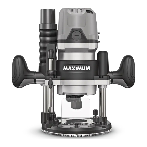
- Page 1 ® Plunge/Fixed-Base Router Model No. 054-2433-0 INSTRUCTION IMPORTANT: MANUAL Please read this manual carefully before using this product, and save it for reference.
-
Page 3: Table Of Contents
® TABLE OF CONTENTS Technical Specifications Safety Guidelines Key Parts Diagram Operating Instructions Maintenance Troubleshooting Parts List Warranty NOTE: If any parts are missing or damaged, or if you have any questions, please call our toll-free helpline at 1-888-670-6682. SAVE THESE INSTRUCTIONS •... -
Page 4: Technical Specifications
054-2433-0 | contact us 1-888-670-6682 TECHNICAL SPECIFICATIONS Rated Voltage 120 V~ 60 Hz Rated Power Input No-load Speed 10,000–25,000 RPM Collet Capacity 1/4 & 1/2” (6.4 & 12.7 mm) -
Page 5: Safety Guidelines
® SAFETY GUIDELINES: WARNING! Safety symbols in this instruction manual are used to flag possible dangers. The safety symbols and their explanations require your full understanding. The safety warnings do not, by themselves, eliminate any danger, nor are they substitutes for proper accident prevention measures. - Page 6 054-2433-0 | contact us 1-888-670-6682 • Keep children and bystanders away while operating a power tool. Distractions can cause you to lose control. ELECTRICAL SAFETY • Power tool plugs must match the outlet. Never modify the plug in any way. Do not use any adaptor plugs with earthed (grounded) power tools.
- Page 7 ® • Do not let familiarity gained from frequent use of tools allow you to become complacent and ignore tool safety principles. A careless action can cause severe injury within a fraction of a second. POWER TOOL USE AND CARE •...
- Page 8 054-2433-0 | contact us 1-888-670-6682 ADDITIONAL SAFETY GUIDELINES FOR THE ROUTER • The label on your tool may include the following symbols. The symbols and their definitions are as follows: V ..... Volts A ..... Amperes Hz ....
-
Page 9: Key Parts Diagram
® PACKAGE CONTENTS: Motor, plunge base, fixed base, collets (1/4 and 1/2"/6.4 and 12.7 mm), wrench, edge guide, centring pin, copy ring, guide bush, 2 chip shields, 3 screws for table mounting, 2 dust-extraction adaptors, depth-adjustment wrench, hard case and instruction manual. - Page 10 054-2433-0 | contact us 1-888-670-6682 PART PART Side handle Live-tool indicator light Spindle-lock button Vacuum port cover Carbon brush cover Micro-adjustment knob Lock-on button Depth-rod locking knob Cord guard Depth-stop turret Trigger switch Chip shield Wheel guard Handle...
-
Page 11: Operating Instructions
® OPERATING INSTRUCTIONS SELECT THE CUTTER BIT This router comes with a 1/2” (12.7 mm) collet and 1/4” (6.4 mm) collet that accept cutter bits with 1/2” (12.7 mm) and 1/4” (6.4 mm) shanks, respectively. The 1/2” (12.7 mm) and 1/4” (6.4 mm) collets can be installed on the tool separately. - Page 12 054-2433-0 | contact us 1-888-670-6682 INSTALL THE CUTTER BIT (fig 2) fig 2 1. Turn the motor off and unplug the router from the power source. Cutter 2. Remove the motor housing from the Bit shank fixed or plunge base.
- Page 13 ® INSTALL THE MOTOR IN THE FIXED fig 3 BASE (fig 3) Coarse- 1. Disconnect the plug from the power adjustment supply. Arrow button 2. Place the fixed base on a flat surface. Motor clamp 3. With the back of the fixed base facing Locking you, open the motor clamp.
- Page 14 054-2433-0 | contact us 1-888-670-6682 CHIP SHIELDS (fig 5) fig 5a FOR FIXED BASE: Chip shield 1. To attach, place the chip shield in position and flex the sides while pushing the shield in until it snaps into place (fig 5a).
- Page 15 ® DEPTH ADJUSTMENT (fig 8) fig 8a 1. Turn off the router. 2. Remove the sub-base from the fixed Sub- base by removing three screws. base Install the fixed base to the router Fixed table referring to the router table’s base instruction manual for detailed installing information.
- Page 16 054-2433-0 | contact us 1-888-670-6682 INSTALL THE COPY RING (fig 10) fig 10 To attach the copy ring onto either the fixed or plunge base, position and secure Copy it to the base with the screws (included). ring...
- Page 17 ® DEPTH ADJUSTMENT WITH THE fig 12 FIXED BASE (fig 12) The fixed base is designed with a fine- Fine- adjustment adjustment system. When the bit is lowered dial to the approximate position desired (coarse Depth- indicator setting), the system can then be micro- ring adjusted to the precise depth.
- Page 18 054-2433-0 | contact us 1-888-670-6682 PLUNGE ACTION WITH DEPTH ROD fig 14 AND DEPTH-STOP TURRET (fig 14) Plunge-depth The depth rod and the depth-stop turret locking lever are used to control the plunge-action Depth rod cutting depth as follows: Depth indicator 1.
- Page 19 ® • To micro-increase the plunge depth, raise the micro-adjustment screw by turning the knob counter-clockwise to the desired amount. • To micro-reduce the plunge depth, lower the micro-adjustment screw by turning the knob clockwise to the desired amount. ON/OFF SWITCH (fig 15) fig 15 1.
- Page 20 054-2433-0 | contact us 1-888-670-6682 LED WORKLIGHTS (fig 17) fig 17 Your router motor has 3 built-in worklights located around the collet to provide high visibility of the workpiece when cutting. These lights are always on when the switch is in the on position...
- Page 21 ® “Climb-Cutting” may cause loss of control, possibly resulting in personal injury. When “Climb-Cutting” is required (e.g., backing around a corner), exercise extreme caution to maintain control of the router. The high speed of the cutter bit during a proper feeding operation (left to right), results in very little kickback under normal conditions.
- Page 22 054-2433-0 | contact us 1-888-670-6682 COPY THE SHAPE (fig 21) fig 21a Screw 1. Mount the guide bush (with guide roller mounted) as illustrated 2. Insert the rods of the edge guide into the base plate. 3. Turn the locking screw clockwise to tighten the rods.
-
Page 23: Maintenance
® MAINTENANCE Before cleaning or performing any maintenance, verify that the router has been disconnected from the power supply. Keep all ventilation openings clean. Avoid using solvents when cleaning plastic parts. Most plastics are susceptible to damage from various types of commercial solvents. Use a clean cloth to remove dirt, oil, and grease. -
Page 24: Troubleshooting
054-2433-0 | contact us 1-888-670-6682 TROUBLESHOOTING PROBLEM Possible Causes Solution Plug is not plugged into Plug the cord into the the power source. power source. Switch is in “OFF” Move the switch to “ON” The router does not position. -
Page 25: Parts List
® EXPLODED VIEW... - Page 26 054-2433-0 | contact us 1-888-670-6682 Part No. Description Part No. Description Internal Wire 3131140000 Top Cover 4860818000 Assembly Internal Wire 4900277000 Speed Adjustor 2822039000 ASSY Power Cord & 4810003000 2740118000 Stator Plug 3131141000 Middle Housing 4870758000 Rocker Switch...
- Page 27 ® Hexagon 5620024000 5650014000 Plain Washer Socket Screw 3660498000 Spring 3553549000 Adjusting Pole Adjusting 5660005000 E Ring 3553550000 Sleeve Compression 5620467000 Screw 3660816000 Spring Depth 5650407000 Wave Washer 3131156000 Indicator Circlips For 5650013000 Plain Washer 5660018000 Shaft 3402540000 Lever 5650525000 Plain Washer 3122840000 Base Plate...
- Page 28 054-2433-0 | contact us 1-888-670-6682 3550713000 Center Pillar 3700806000 Guide Bush Depth Vacuum 3402220000 Adjusting 3131154000 Adapter Lever Collet 2823125000 5630056000 Wing nut Assembly 3550588000 Guiding Rod 5620075000 Screw 3703925000 Fence 2824535000 Bolt And Nut Guide Bush 3400204000...
-
Page 29: Warranty
(with the same model, or one of equal value or specification), at the sole discretion of the MAXIMUM Canada authorised repair centre (“Service Provider”). We will bear the cost of any repair or replacement and any costs of labour relating thereto. - Page 30 This warranty applies for a period of 5 years from the date of original retail purchase, as indicated on the bill of sale. Neither the retailer, MAXIMUM Canada, nor the manufacturer shall be liable for any other expense, loss or damage, including, without limitation, any indirect, incidental, consequential or exemplary damages arising in connection with the sale, use or inability to use this product.
- Page 31 In addition to the 5-Year Limited Warranty, this MAXIMUM product is covered by our: 1-Year Repair Warranty...
Need help?
Do you have a question about the 054-2433-0 and is the answer not in the manual?
Questions and answers