Table of Contents
Advertisement
Advertisement
Table of Contents

Related Manuals for Daikin FDYQN71LBV1


Summary of Contents for Daikin FDYQN71LBV1
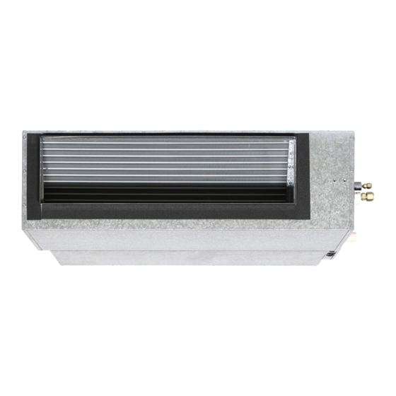
- Page 1 INSTALLATION MANUAL DUCTED SYSTEM Air Conditioners MODELS (Ceiling concealed duct type) FDYQ(N)71LBV1, FDYQ(T/N)100LBV1 FDYQ(T)125LBV1 FDYQ(T)140LCV1 FDYQ(T)160LBV1 PLEASE READ THESE INSTRUCTIONS CAREFULLY BEFORE INSTALLATION. KEEP THIS MANUAL IN A HANDY PLACE FOR FUTURE REFERENCE.
-
Page 3: Table Of Contents
CONTENTS SAFETY CONSIDERATION.....................3 BEFORE INSTALLATION....................4 SELECTING INSTALLATION SITE.................5 PREPARATIONS BEFORE INSTALLATION..............6 INDOOR UNIT INSTALLATION..................7 REFRIGERANT PIPING WORK..................7 DRAIN PIPING WORK.....................9 ELECTRICAL WIRING WORK..................10 WIRING EXAMPLE......................12 FIELD SETTINGS......................14 TEST OPERATION......................19 CHECKING PROCEDURE FOR ERROR RECORD............22 REGISTRATION METHOD OF THE SERVICE CONTACT........23 SEPARATING THE INDOOR UNIT (If required) FDYQ(T)(N)71-160......24 ERROR CODE LIST.......................26... -
Page 4: Safety Consideration
Installation Manual Installation Manual FDYQ(N)71LBV1, FDYQ(T/N)100LBV1 FDYQ(T)125LBV1, FDYQ(T)140LCV1, FDYQ(T)160LBV1 SAFETY CONSIDERATIONS Please read there “SAFETY CONSIDERATIONS” carefully before installing the air conditioning equipment and be sure to install it correctly. After completing the installation, make sure that the unit operates properly during the start-up operation. Please instruct the customer on how to operate the unit and keep it maintained. -
Page 5: Before Installation
Shape OPTIONAL ACCESSORIES • A Daikin remote controller is not included in the packaging with the indoor unit. It needs to be purchased separately. Install the remote controller in an appropriate place. If utilizing the temperature sensor in the remote controller BRC1E62 (see page 14) ensure that the controller is installed in a location where the correct air temperature is measured. -
Page 6: Selecting Installation Site
Installation Manual NOTE TO THE INSTALLER Be sure to instruct the customer how to properly operate the system (especially cleaning filters, operating the different functions and adjusting the temperature). It is recommended to ask the customer to carry out the operations themselves while you instruct them and refer them to the applicable place in the operation manual. -
Page 7: Preparations Before Installation
Installation Manual • Hanging brackets are sold as an optional accessory. (3) If the installation requires the indoor unit to be exposed please ensure the unit is more than 1.8m above the floor so that children can not touch the unit. (4) A suitable air filter (field supplied) must be installed within the return air duct. -
Page 8: Indoor Unit Installation
Installation Manual (2) Install the suspension bolt. (Fig. 3 & 4) Ceiling slab (Use M10 size rod for the suspension bolt) Use and anchor suitable for both the material being Anchor anchored to and the weight of the unit. Long nut or turn-buckle (3) Be sure to completely insulate all external duct work Suspension bolt and fittings. - Page 9 Installation Manual • Be sure to use both a spanner and torque wrench together, as shown in the diagram, when connecting or disconnecting pipes to/from the unit. (Fig. 7) • Use only a flaring block suitable for R410A tube. Refer to Table 2 for the specifications of the flare work. •...
-
Page 10: Drain Piping Work
Installation Manual Not recommended but in case of an emergency You must use a torque wrench but if you are obliged to install the unit without a torque wrench, you may follow the installation method below. As you keep on tightening the flare nut with a spanner there is a point where the tightening torque suddenly increases. -
Page 11: Electrical Wiring Work
Installation Manual Safety drain tray Bottom of the unit (field supplied) Large sealing pad Metal clamp 1 (field supplied) Metal clamp 1 (provided) Drain hose 2 Drain hose 2 (provided) Tape (white) 4mm or less Fig. 11 NOTE: • If installing central drain piping, install according to Fig. - Page 12 Installation Manual Method of wiring. - Refer to Fig. 14 for the wiring details. NOTE: All wires must be wired through bushes at the bottom of the electrical box. • Remove the electrical box cover as indicated. • Power and earth wiring. Connect the power supply wires to terminals (L, N).
-
Page 13: Wiring Example
Installation Manual PRECAUTIONS Precaution for wiring on site When connecting the indoor unit to a single phase of 3 phase power supply, give consideration to the other electrical equipment connected to the main breaker and select the phase (L1, L2, L3) so that the current (or voltage) unbalance does not occur. - Page 14 Installation Manual Single phase pair type Control by 2 remote controllers Main power supply Main power supply Main power supply Main power supply Fuse Fuse Fuse Fuse Main power supply Isolation switch Isolation switch Main power supply Isolation switch Isolation switch Fuse Fuse 1 2 3...
-
Page 15: Field Settings
Installation Manual Field Settings How to Change the Field Settings with the Wired Remote Controller The following functions of indoor unit can be changed from the remote controller. At the item of installation or after service inspection / repair, make the local setting in accordance with the following description. Wrong setting may cause malfunction. - Page 16 FAN MANUAL SETTING Daikin FDYQ-L Series Ducted Fan Coil units employ a high efficiency DC Fan Motor operating in combination with a Daikin proprietary microprocessor based motor management system. The DC Fan Motor contains multiple motion sensor devices that monitor the motor’s rotation and speed. The output from these devices is constantly compared against target data in the motor management system which subsequently makes adjustments to the motor input waveform to maintain the target motor speed.
- Page 17 Installation Manual Press “ “ (Down/Up) button until Mode appears. Press “ “ (Right/Left) button Unit No. Mode to go to 7-01 0-01 1-01 2-01 3--- 4-01 5--- 6-04 7-01 Change settings to 7-03 by pressing 8-08 9-08 a--- b--- “...
- Page 18 Installation Manual OTHER SETTINGS (Applicable to all models) Ducted Air Conditioners...
- Page 19 Installation Manual CONTROL BY 2 REMOTE CONTROLLERS • Check for completion of indoor/outdoor units wiring. • Check for closing of EL. COMPO. BOX cover of indoor and outdoor units before power-on. Following is displayed after turn on the power. “Checking the connection. Please stand by.”...
-
Page 20: Test Operation
Installation Manual TEST OPERATION when using BRC1E62 remote control. Please use zone controller installation instructions). Refer to the selection of “FOR THE FOLLOWING ITEMS, TAKE SPECIAL CARE DURING CONSTRUCTION AND CHECK AFTER INSTALLATION IS FINISHED”. Also see installation manual supplied with the outdoor unit. •... - Page 21 Installation Manual Press ON/OFF button within about 10 seconds. The test operation starts. Check operation condition for 3 minutes. Note) In the case of above men- tioned procedures in reverse order, test operation can start as well. Press Airflow Setting button. Select airflow direction setting by pressing the “...
- Page 22 Installation Manual Press Menu/Enter button in the Basic screen. Main menu screen is dis- played. Select Maintenance Information the Main menu, and press Menu/Enter button. Maintenance Information screen is displayed. Check that malfunction (error) code history is not displayed in the screen.
-
Page 23: Checking Procedure For Error Record
Installation Manual Checking procedure of Malfunction (Error) History Press and hold Cancel button for 4 seconds or longer in the Basic screen. Service Settings menu is displayed. Select Error History in the Service Settings menu, and press Menu/Enter button. The Error History menu screen is displayed. -
Page 24: Registration Method Of The Service Contact
Installation Manual Registration method of the Maintenance Contact Registration of the service contact. Press and hold Cancel button for 4 seconds or longer in Basic screen. Service Settings menu is displayed. Select Maintenance Contact in the Service Settings menu, and press Menu/Enter button. -
Page 25: Separating The Indoor Unit (If Required) Fdyq(T)(N)71-160
Installation Manual Confirmation of registered details Press Menu/Enter button in the Basic screen. Main menu is displayed. Select Maintenance Information the Main menu, and press Menu/Enter button. Press Cancel button twice. The Basic screen returns. SEPARATING THE INDOOR UNIT FDYQ(N)71LB1V AND LARGER MODELS Fig. - Page 26 Installation Manual • Reassemble the fan deck and heat exchanger compartments in the following order: 9) Carefully place the fan deck back in the position. 10) Secure the fan deck onto the heat exchanger compartment with the (4) M8 bolts. (Fig. 21) 11) Carefully replace the fan deck compartment, taking care not to damage the fan motor wiring.
-
Page 27: Error Code List
Installation Manual Ducted Air Conditioners... - Page 28 DAIKIN AUSTRALIA PTY. LIMITED 62-66 Governor Macquarie Dr, Chipping Norton, NSW 2170 Australia Phone: 1300 36 24 38 Dakin New Zealand, 525 Great South Rd, Penrose, Auckland 6 www.daikin.com.au DAIKIN INDUSTRIES LTD. Head office: Umeda Centre Bldg., 2-4-12, Nakazaki-Nishi, Kita-ku, Osaka, 530-8323 Japan Tokyo office: JR Shinagawa East Bldg., 2-18-1, Konan,...
Need help?
Do you have a question about the FDYQN71LBV1 and is the answer not in the manual?
Questions and answers
I have two of these machines and one of them has a loud noise coming from it, the noise is from one of the two wheel turbines inside but I don’t see anything loose or caught in them