Advertisement
Quick Links
Thank you for purchasing a Sealey Product. Manufactured to a high standard this product will, if used according to these instructions
and properly maintained, give you years of trouble free performance.
IMPORTANT: PLEASE READ THESE INSTRUCTIONS CAREFULLY. NOTE THE SAFE OPERATIONAL REQUIREMENTS,
WARNINGS AND CAUTIONS. USE THIS PRODUCT CORRECTLY AND WITH CARE FOR THE PURPOSE FOR WHICH IT IS
INTENDED. FAILURE TO DO SO MAY CAUSE DAMAGE AND/OR PERSONAL INJURY AND WILL INVALIDATE THE WARRANTY.
PLEASE KEEP INSTRUCTIONS SAFE FOR FUTURE USE.
1.
SAFETY INSTRUCTIONS
1.1
GENERAL SAFETY
IMPORTANT! These instructions are offered as a guide only, albeit compiled with good practical user advice. Always refer to the vehicle
manufacturer's service instructions, or a proprietary manual to establish the current procedure and data.
WARNING! Ensure Health & Safety, local authority, and general workshop practice regulations are adhered to when using this tool.
WARNING! Familiarise yourself with the specific applications and limitations of the kit, as well as any potential hazards.
WARNING! This tool is heavy, over 7kg, two people recommended for some tasks.
This kit should be used in conjunction with inspection maintenance procedures recommended in the vehicle manufacturer's manual.
Ensure that the kit is correct for the task.
Wear the appropriate personal protective equipment for the task. A full range is available from your Sealey dealer.
DO NOT use the kit for any purpose other than that for which it is designed.
Ensure that the vehicle is properly supported with axle stands before working under the vehicle.
Ensure there is adequate lighting prior to using the kit. A range of inspection lamps are available from your Sealey dealer.
Keep children and unauthorised persons away from the working area.
DO NOT use the kit if any parts are damaged or missing, as this may cause failure and/or personal injury.
DO NOT use the kit when you are tired, or under the influence of alcohol, drugs or intoxicating medication.
After use, store in a safe, dry childproof area.
Warning! Failure to adhere to safety and warning instructions may result in personal injury or
damage which would invalidate the warranty. The bush extraction and insertion screw maximum
recommended torque is 180Nm. Exceeding this torque value may shorten the life of the thrust screw
and distort other components. The thrust screw is considered to be a consumable item and is NOT
covered under warranty. Always lubricate the threads male and female with a molybdenum/copper
based grease after removing from the carry case.
ALWAYS KEEP FORCE SCREW
WELL LUBRICATED. MOLYBDENUM
COPPER BASED RECOMMENDED.
2.
INTRODUCTION
Suitable for the removal/installation of the rear trailing arm mounting bushes on Ford vehicles. Can be used in situ without removing the
arm from the vehicle. Also suitable for some Volvo vehicles that share the same Ford platform. Supplied in carry-case.
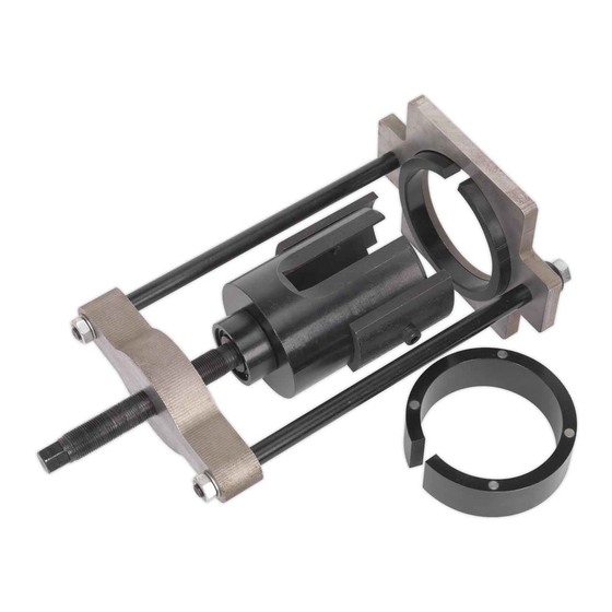
3.
APPLICATIONS
Fig.1
© Jack Sealey Limited
INSTRUCTIONS FOR:
TRAILING ARM BUSH TOOL FORD
MONDEO Mk4
MODEL No:
Make
Model
Ford
Mk4 Mondeo
Ford
S-Max
Ford
Galaxy
Volvo
S60, S80, XC60, V70, XC70 2006 - 2009 with Ford Platform
Offside Trailing Arm Removed From Vehicle C/W Bush Assembly
Orientation mark see
Fig.7 and note 5.1.4
Original Language Version
VSE4784
DO NOT USE AIR TOOLS
TO OPERATE FORCE SCREW
Year
2007 - onward
2006 - onward
2006 - onward
Bush Assembly (R)
VSE4784
Issue No.2 - 07/11/16
Advertisement

Related Manuals for Sealey VSE4784


Summary of Contents for Sealey VSE4784
- Page 1 VSE4784 MODEL No: Thank you for purchasing a Sealey Product. Manufactured to a high standard this product will, if used according to these instructions and properly maintained, give you years of trouble free performance. IMPORTANT: PLEASE READ THESE INSTRUCTIONS CAREFULLY. NOTE THE SAFE OPERATIONAL REQUIREMENTS, WARNINGS AND CAUTIONS.
- Page 2 Depth Control Legs (Fig.5 item 2) Two Segments nest either side of the adaptor fixed with M8 screws. Only used when inserting new bush to correct depth. Fig.5 BUSH REMOVAL Rivet stud Rivet stud I/D Stamped I/D Stamped Nearside Offside Fig.6 Bush Assembly Identification Original Language Version VSE4784 Issue No.2 - 07/11/16 © Jack Sealey Limited...
- Page 3 Arm (Fig.1) spanner only required, the clear opening height is governed by the studs. Thrust Screw Cylindrical Adaptor 15mm "C" Ring Old Bush Assembly Removal Details Fig.13 Bottom Plate Original Language Version VSE4784 Issue No.2 - 07/11/16 © Jack Sealey Limited...
- Page 4 INSERTING NEW BUSH NOTE! Illustrations hereafter are with a section of the trailing arm removed from the vehicle and are all "R" (offside) assembly. Refer to manufacturer's service manual, or proprietary manual when using these instructions. 6.1.1 Clean the bore of pressed steel bush housing of any residual oil or grit. No lubricant or 'free release fluid' is to be present on the bush sleeve or the housing bore. 6.1.2 Place the new bush "Tee" plate inside the adaptor and locate the bush sleeve over reduced diameter and shoulder. It will only fit squarely one way.