Table of Contents
Advertisement
Quick Links
Advertisement
Table of Contents

Related Manuals for Hitachi EC701HP


Summary of Contents for Hitachi EC701HP
- Page 1 Operation Manual 700W UHF 8VSB-ATSC Transmitter EC701HP Rodovia BR 459 - KM 121, 121A - Córrego Raso - 37540-000 - Santa Rita do Sapucaí - MG - Brasil Tel: (+5535) 3473-3473 - Fax: (+5535) 3473-3474 | linear@linear.com.br - www.hitachi-linear.com.br...
- Page 2 W A R N I N G All rights reserved. No part of this manual may be reproduced or transmitted in any form, by any means (electronic, photocopying, recording or otherwise) without the prior permission of the publisher, except where permitted by law.
- Page 3 Hitachi Kokusai Linear Equipamentos Eletrônicos S/A TECHNICAL ASSISTANCE n our Quality Management System, since several devices are received without proper identification and explanations; we are now working with previous approval for maintenance devolution. herefore, in case of maintenance please contact: Hitachi Kokusai Linear Equipamentos Eletrônicos S/A...
- Page 4 Hitachi Kokusai Linear Equipamentos Eletrônicos S/A WARNING MANDATORY CONDITIONS FOR TRANSMITTER INSTALATION, FOR VALIDATING THE WARRANTY TERMS 1. Proper grounding; 2. Proper lightning-rod; 3. Shelter with ventilation, foot-print, and temperature in compliance with the transmitter’s standards. 4. Voltage regulator in compliance with transmitter’s consumption.
- Page 5 It is important to have isolation between energy stations of the shelter and the TV transmitter, which is achieved with the usage of isolator transformers. Thus is guaranteed that no AC Mains’ transient coming from the shelter will be passed on to the TV transmitter or vice-versa. Besides, Hitachi Kokusai Linear’...
-
Page 6: Table Of Contents
Technical Specification - E-Compact TV ATSC Power Network Connections ......3-18 Transmitters ............1-20 3.6.1 Power Feeding Options ......3-18 Photo - EC701HP Tansmitter ......1-21 3.6.2 AC Power Cable Connections ..3-18 On Site Physical Assembly ....... 3-19 Section 2 - Minimum Installation 3.7.1... - Page 7 Section 5 - System Operation Manual Remote Management System (Telesupervision) 5-47 Introduction ..............5-1 5.8.1 IP Configuration ........... 5-47 5.1.1 Front Panel ............ 5-1 5.8.2 Mask Configuration ........5-48 Digital Exciter - The Master Control Unit ....5-1 5.8.3 Gateway Configuration ....... 5-48 5.2.1 Keypad ............
-
Page 8: Section 1 - Introduction
The purpose of this manual is to provide the technical information required for the installation and operation of transmitters in UHF TV signals (digital ATSC) in the E-Compact series. Hitachi Kokusai Linear Electronic Equipment S/A recommends that you carefully read the sections of this manual before installing or operating this equipment. -
Page 9: General Description
Included in this section are the functional description of power drawers and digital exciter, block diagrams and technical specifications of the system. EC708HP EC712HP EC706HP EC704HP EC703HP EC702HP EC701HP 40RU 2x 40RU 25RU Image for illustrative purpose Figure 1-1 Front View ATSC Transmitters Manual Rev. 0.1 - February 2018... -
Page 10: Transmitter's Control System
1.4.1 Transmitter’s Control System Control Architecture for Hitachi Kokusai Linear’ Transmitters: Hitachi Kokusai Linear’s transmitter control system allows control and monitoring, through front display, all parameters of the equipment. This system is comprised by a control unit (exciter’s integrated function) which through a RS485/ MODBUS network, gather and sends information to the power drawers. - Page 11 Table 1-1 Addresses of power drawers and Exciters - MODBUS Pinout configuration MODEL MODULE ADDRESS MODBUS (decimal) (MSB) A2 A1 A0 (LSB) (binary) EC701HP PA Drawer #1 PA Drawer #1 EC702HP PA Drawer #2 PA Drawer #1 EC703HP PA Drawer #2...
- Page 12 Section 1 - Introduction (UHF Digital TV Transmitters) E-Compact - Air Cooling - ATSC - High Power The Architecture of Control for Hitachi Kokusai Linear Transmitters is composed of subcontrol blocks characterized by Control / Exciter Drawers and by Power Drawer. This architecture allows the distribution of control functions.
-
Page 13: E-Compact Atsc Transmitters Models
The combiner is present only on devices with more than one power drawer. (*4) The components of the AC input (In-Rush, circuit breakers, etc.) of the transmitter are contained in a drawer called MCCB (except EC701HP model). MCCB: Moulded Case Circuit Breaker. Manual Rev. 0.1 - February 2018... -
Page 14: Block Diagram Of The System
Section 1 - Introduction (UHF Digital TV Transmitters) E-Compact - Air Cooling - ATSC - High Power 1.4.4 Block Diagram of the System Figure 1-2 contains the block diagram of the 700W transmitter, EC701HP model. Manual Rev. 0.1 - February 2018... -
Page 15: Functional Description Of The System
Section 1 - Introduction (UHF Digital TV Transmitters) E-Compact - Air Cooling - ATSC - High Power 1.4.5 Functional Description of the System 1.4.5.1 ATSC Digital Exciter The exciter is formed by the MOD GV 40153 module drawer more optional (internal GPS, and other software optional). - Page 16 Major changes on the transmitter configuration are possible with factory assistance. The Digital Exciter interacts with the HITACHI proprietary software (GUI8001) that performs the implementation of linear and non-linear pre-correction as required; the software also conducts measurements on the demodulated signal, such as MER and power spectrum readings, among others.
- Page 17 Section 1 - Introduction (UHF Digital TV Transmitters) E-Compact - Air Cooling - ATSC - High Power Block Diagram - Digital Exciter Figure 1-5 contains the 1st part of the block diagram of the exciter 100mW. Manual Rev. 0.1 - February 2018 1-10...
- Page 18 Section 1 - Introduction (UHF Digital TV Transmitters) E-Compact - Air Cooling - ATSC - High Power 17dB 17dB 17dB 17dB Manual Rev. 0.1 - February 2018 1-11...
- Page 19 Section 1 - Introduction (UHF Digital TV Transmitters) E-Compact - Air Cooling - ATSC - High Power Description of main circuits: Equalizer input circuit ASI 1 e 2 Equalize and convert DVB-ASI signal into a differential LVDS signal to the FPGA. Circuit Cable Driver of the outputs ASI 1 e 2 Converts the LVDS signal provided by the FPGA to DVB-ASI electrical standard.
- Page 20 Section 1 - Introduction (UHF Digital TV Transmitters) E-Compact - Air Cooling - ATSC - High Power Digital-to-Analog Converter and Analog FI generation Composed of the DA converter, reconstruction filter (low pass with fc ~ 50MHz) and FI amplifier. The DA converter operates at 172.0195804 MSPS (interpolation factor equal to 2) and the output amplifier with gain of 7dB has a protection circuit that inhibits its operation during the transient power supply and system startup.
-
Page 21: Coaxial Relay (Optional Dual Excitation)
3U Power Drawer for 19" rack N represents the number of drawers of the transmitter. The EC701HP equipment uses the MOD GV 40087 drawer. What differs from the drawer MOD GV 40001 are the models of adders and back panel connectors. - Page 22 Section 1 - Introduction (UHF Digital TV Transmitters) E-Compact - Air Cooling - ATSC - High Power Power Amplifiers which cover the entire UHF band Power transistors LDMOS NXP BLF888A Automatic control of the quiescent currents of the power transistors depending on the temperature.
- Page 23 Section 1 - Introduction (UHF Digital TV Transmitters) E-Compact - Air Cooling - ATSC - High Power Figure 1-9 - Front view of the power drawer Table 1-3 Power Drawer Technical Specification CHARACTERISTIC SPECIFICATION Input Impedance 50 ohms Loss of input return Better than 19dB RF Input connector Plug-in...
-
Page 24: Power Combiner
Section 1 - Introduction (UHF Digital TV Transmitters) E-Compact - Air Cooling - ATSC - High Power 1.4.5.5 Power Combiner This module is a passive RF combiner N doors constructed with hybrid couplers, which is a (*5) combination of N: 1 from the output of the N power drawers, thus obtaining the final transmitter power. -
Page 25: Filtering System
Section 1 - Introduction (UHF Digital TV Transmitters) E-Compact - Air Cooling - ATSC - High Power 1.4.5.7 Filtering System The TV transmitter is endowed with a filtration system that ensures that the spectral conformity of the TV channel broadcast on UHF stay in accordance with the parameters set by international standards (FCC, ITU and Anatel). -
Page 26: Electrical Distribution Drawer (Mccb)
The MOD GV MCCB drawer has different power capacities according to the respective transmitter models, requiring the transmitter power specification. Table 1-4 Models of electric distribution drawer (MCCB) as the transmitter model TRANSMITTER MODEL MCCB MODEL EC701HP NOT APPLICABLE EC702HP MOD GV 40031 MCCB EC703HP... -
Page 27: Technical Specification - E-Compact Tv Atsc Transmitters
11,807 15,710 23,515 ISDB-T 1,935 3,810 5,685 7,560 11,310 15,060 22,620 Except for model EC701HP, nominal power of 580W, in which the minimum power is 50W. Typical Heat Dissipation (BTU/h) May change depending on MER ATSC 4,539 8,551 12,656 16,618... -
Page 28: Photo - Ec701Hp Tansmitter
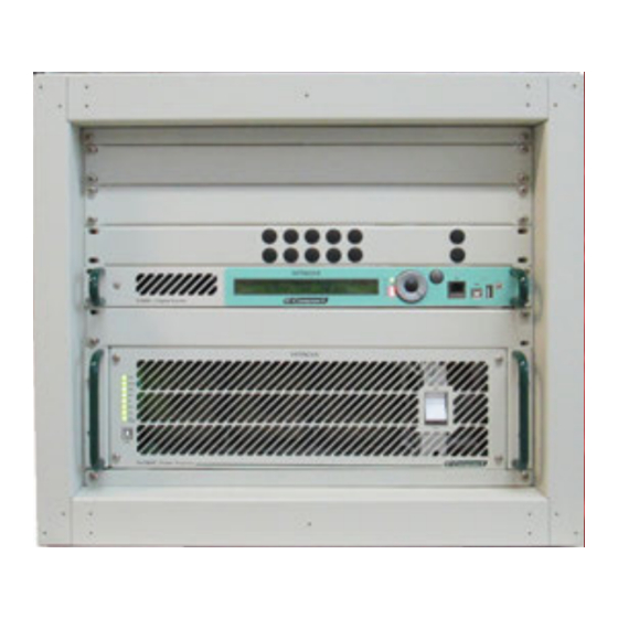
Section 1 - Introduction (UHF Digital TV Transmitters) E-Compact - Air Cooling - ATSC - High Power Photo - EC701HP Transmitter Figure 1-13 - Front view of the EC701HP Manual Rev. 0.1 - February 2018 1-21... - Page 29 Section 1 - Introduction (UHF Digital TV Transmitters) E-Compact - Air Cooling - ATSC - High Power E-Compact Series - Installation CheckList (Use before turning the transmitter on for the first time) Task Description Electrical. External Grounding from the AC panel. Grounding Cabinet.
-
Page 30: Section 2 - Minimum Installation
Moreover, it must be checked the potential difference between the ground and neutral (if any) terminals to be connected to the Hitachi Kokusai Linear TV transmitter. Such potential difference must be maximum 3V. -
Page 31: Insulation
UPS devices, i.e. 30% above the specified TV transmitter consumption in kVA. The Hitachi Kokusai Linear TV transmitter should not be installed within a radius of 10 meters from the 13kVA transformer, as it could cause interferences due to the electromagnetic field or sparking in the internal brushes. - Page 32 Section 2 - Minimum Installation Requirements (E-Compact ATSC Transmitters) Important to note that UPS does not necessarily need to have a battery bank, thus minimizing the cost of the final product. This solution is much better than a conventional stabilizer due to double conversion as explained earlier.
-
Page 33: Atmospheric Discharge Protection System
Section 2 - Minimum Installation Requirements (E-Compact ATSC Transmitters) STATIC BYPASS DELTA TRANSFORMER MAIN INVERTER DELTA CONVERTER BATTERY Figure 2-3 - No-Break on-line Delta Conversion Atmospheric Discharge Protection System 2.3.1 Lightning Arresters The Atmospheric Discharge Protection System comprises the lightning arresters and their elements. -
Page 34: Air Conditioning
• MEDIUM POWER E-COMPACT TV TRANSMITTERS: from 0º to 30ºC • HIGH POWER E-COMPACT TV TRANSMITTERS: from 0º to 25ºC If a Hitachi Kokusai Linear equipment is damaged due to the lack or inefficiency of the air conditioning system, it shall NOT be covered by the guarantee. - Page 35 Thank you for selecting Hitachi LINEAR for your TV Broadcast needs. The transmitter you are about to install was tested and approved by Hitachi LINEAR quality control. It is factory set on the requested channel and output power, and in accordance with ANATEL regulations.
- Page 36 ELECTRONIC EQUIPMENT. THE INSTALLATION, OPERATION, AND MAINTENANCE OF THIS EQUIPMENT INVOLVE RISKS TO PERSONNEL AND ALSO TO THE EQUIPMENT. HITACHI KOKUSAI LINEAR SHALL NOT BE RESPONSIBLE FOR INJURY OR DAMAGE THAT IS THE RESULT OF IMPROPER PROCEDURES OR USE BY INDIVIDUALS IMPROPERLY TRAINED OR LACKING THE KNOWLEDGE TO PERFORM ASSOCIATED TASKS.
- Page 37 Returns and Exchanges Equipment (Damaged or undamaged) should not be returned unless written approval and a Merchandise Return Authorization (MRA Number) is received from your Linear Sales representative or Linear Customer Service. Special shipping instruction will be provided which will assure proper handling. The circumstances and reasons for the return must be included in the request for return.
-
Page 38: Section 3 - Installation
Such notice would be used to establish the responsibilities for the product integrity. Hitachi Kokusai Linear carries out operating tests at the factory on every transmitter in order to ensure proper operation after delivery to the user. Nevertheless, if the equipment does not operate after the start-up and there is no evidence of transportation damage, it might be necessary to send the equipment back to the factory for repair or replacement. -
Page 39: Tower
Section 3 - Installation (ATSC EC701HP Transmitter) 3.3.2 Tower For the installation of the TV transmission and reception system, the tower must be made with hot-dip galvanized steel. A lightning protection system should be installed in the tower as well as nocturnal beacons bulbs with red glass. - Page 40 Section 3 - Installation (ATSC EC701HP Transmitter) Distance between the Rx and Tx Antennas They should be placed as far as possible from each other in order to isolate the transmitted signal from the received signal. Polarization It is very important to verify the polarization of the received signal, which can be vertical, horizontal or circular.
-
Page 41: Equipment Installation Indoors
Section 3 - Installation (ATSC EC701HP Transmitter) 3.3.4 Equipment Installation Indoors Small equipments must be placed on a table in a way to provide easy access from all sides and be at least one meter far from the walls. Do not place anything on the top of the equipment in order not to compromise its natural ventilation. -
Page 42: Electric Installation Grounding
Section 3 - Installation (ATSC EC701HP Transmitter) 3.3.6 Electric Installation Grounding The shelter installations receive power through an aerial power line. Moreover, because of it, the lightning discharges that might hit the power lines generate power surges that can reach the shelter and consequently the equipments. -
Page 43: Mechanical Drawings
Section 3 - Installation (ATSC EC701HP Transmitter) Mechanical Drawings This section shows the mechanical drawings relative to the external structure of the equipment, including location of drawers. 3.4.1 Front View RF SAMPLING PROBE MOD 40052 SOND 158-158 LOW PASS FILTER... -
Page 44: Rear View
Section 3 - Installation (ATSC EC701HP Transmitter) 3.4.2 Rear View Figure 3-2 Rear wiew - Model EC701HP (rack of 8 units) Manual Rev. 0.0 - March 2018... -
Page 45: Isometric View
Section 3 - Installation (ATSC EC701HP Transmitter) 3.4.3 Isometric View Figure 3-3 Isometric View - Model EC701HP Manual Rev. 0.0 - March 2018... -
Page 46: Dimensions (Mm)
Section 3 - Installation (ATSC EC701HP Transmitter) 3.4.4 Dimensions (mm) Figure 3-4 - Front view Figure 3-5: Side view Manual Rev. 0.0 - March 2018... -
Page 47: Top View
Section 3 - Installation (ATSC EC701HP Transmitter) 3.4.5 Top view LOW PASS FILTER MOD 40055 Figure 3-6 Top view of EC701HP Manual Rev. 0.0 - March 2018 3-10... -
Page 48: Front Panel
Section 3 - Installation (ATSC EC701HP Transmitter) Front Panel The transmitter's front panel provides access to the following drawers: Digital Exciter and Power Drawer. 3.5.1 Digital Exciter The Digital Exciter's front panel contains the display, the initialization LEDs and the keyboard. - Page 49 Section 3 - Installation (ATSC EC701HP Transmitter) Rear Panel The following elements are located in the digital exciter's rear panel: 1- On/Off switch 2- 3-pin AC feeding connector. 3/ 11- Air output. 4- USB Port - USB Device Port, used for GUI8001...
- Page 50 Section 3 - Installation (ATSC EC701HP Transmitter) 16- RF OUTPUT Function: RF signal output Type: N female Impedance: 50 17- CAM Function: Conditional Access Module compatible with IRDETO cards and CONAX. Supports multiple services. Type: PCMCIA 18- AFTER F.
-
Page 51: Power Drawer
Section 3 - Installation (ATSC EC701HP Transmitter) 3.5.2 Power Drawer INDICATOR LEDS USB INTERFACE ON/OFF SWITCH Figure 3-9 Front View of Power Drawer - Module MOD GV 40001 / 40087 Changing Functions of the LED’s of the GV 40001 front panel... - Page 52 Section 3 - Installation (ATSC EC701HP Transmitter) PLUG-IN RF OUTPUT CONNECTOR RF INPUT POWER SUPPLY FUSE AC INPUT CONTROL INTERFACE Figure 3-10 Rear view of the Power Drawer - Model MOD GV 40001 Identification: The following elements are located in the power drawer's rear panel: RF OUT - Unflanged 7/8"...
- Page 53 Section 3 - Installation (ATSC EC701HP Transmitter) POWER SUPLLY FUSÍVEL DA FONTE DE ALIMENTAÇÃO FUSE RF OUTPUT RF SAMPLE RF INPUT ENTRADA RF AC INPUT CONTROL INTERFACE ENTRADA AC INTERFACE DE CONTROLE Figure 3-12 Power drawer's rear panel - MOD GV 40087 model...
-
Page 54: Top Panel
Section 3 - Installation (ATSC EC701HP Transmitter) 3.5.3 Top Panel 4,5- TURN IN A / TURN IN B (optional) Function: RF Signal Input (VHF / UHF) Type: F Female 1 2 3 6,8- GPS ANTENNA IN A / GPS ANTENNA IN B (opt.) Function: Antenna input for the GPS module... -
Page 55: Power Network Connections
If the network structure is changed without previous notice, the transmitter guarantee shall be suspended. NEVER change the transmitter's network structure without previous instruction from Hitachi Kokusai Linear Equipamentos Eletrônicos S/A's Digital Support department. Undue or mistaken changes could not only endanger the equipment, but also the people operating it. -
Page 56: On Site Physical Assembly
Section 3 - Installation (ATSC EC701HP Transmitter) ON SITE PHYSICAL ASSEMBLY NOTE: trained personnel ONLY should conduct the on-site physical assembly. ATTENTION The following precautions should be taken when positioning the transmitter at the installation site: 1) The air intake (front) and air outlet (back) should be completely clear. - Page 57 Section 3 - Installation (ATSC EC701HP Transmitter) 3- Insert and fasten the power drawer in the rack. 4- Insert and fasten the digital exciter B. 5- Insert and fasten the digital exciter A. 6- Insert and fasten the Ethernet* switch 7- Check the presence and physical integrity of all the drawers' power feeding and communication points.
-
Page 58: Connections
Section 3 - Installation (ATSC EC701HP Transmitter) 3.7.2 Connections 3.7.2.1 Internal Connections The following connections must be made: - RF cables - AC power cables and grounding of the exciter - AC power cables and grounding of the power drawer... - Page 59 Figure 3-18 AC Input cable, ON/OFF switch and fusible - Module 4992 Connect the grounding mesh in the GND screw on the rear panel of exciter. Section 3 - Installation (ATSC EC701HP Transmitter) EX CITER SCREW GROUNDING Figure 3-19 Screw grounding - Digital Exciter GND: Ground - Connect this terminal to ground at the installation site.
- Page 60 Section 3 - Installation (ATSC EC701HP Transmitter) C- Power Drawer AC Power Cable Locate the power cable attached to the side of the rack. Connect the power cable to the power drawer. AC IN CABLE Figure 3-20 AC IN cable - Power drawer (MOD GV 40087)
- Page 61 Section 3 - Installation (ATSC EC701HP Transmitter) E- Transport Stream ASI Cables Connect the cables from the top panel of the transmitter to the respective connectors on the rear panel of the exciter (MOD GV 4992). Figure 3-22 ASI cables input - MOD GV 4992 ...
- Page 62 Section 3 - Installation (ATSC EC701HP Transmitter) ORIGIN – T RANSMITTER TOP Connector COVER FROM CABLE TYPE Description CABLE Connector Description RF AFTER FILTER IN A Exciter AFTER F. N(F) –SMA(M) RG316 50 Ohms TURN IN A xcite TURN IN F(F) –SMA(M) RG316 50 Ohms...
-
Page 63: External Connections
Section 3 - Installation (ATSC EC701HP Transmitter) 3.7.2.2 External Connections The following external connections must be made: - AC power feeding - Grounding - Rigid line / Filter / Antenna - Transport Stream IN A- AC Power Feeding Pass the AC power feeding cables through the hole at the rack bottom and connect them to the AC input connector. - Page 64 Section 3 - Installation (ATSC EC701HP Transmitter) B- Grounding Insert the ground cable through the hole and connect it to the screw at the bottom of the rack. GROUNDING SCREW GROUNDING SCREW Figure 3-26 Grounding screws - Bottom of...
- Page 65 Section 3 - Installation (ATSC EC701HP Transmitter) D- Programming a. The transmitter is ready to receive ASI transport streams as programming source. b. Programming BNC connector is located on the top panel of the transmitter. c. Connect the applicable signal cables on the top cover of the rack.
-
Page 66: Section 4 - Initial Activation
Section 4 - Initial Activation (ATSC Transmitters) Section 4 Initial Activation Introduction After finishing the installation, the equipment is ready to be activated. It is important to observe that the transmitter is configured at the factory with the parameters that were supplied by the customer at the time he made the purchase, such as the channel output, power, MER, etc. - Page 67 Section 4 - Initial Activation (ATSC Transmitters) Setting the output power to 0 watts For security purposes, access the power programming screen (POWER SETUP [1100]) of the exciter by Menu navigation software, no display digital and set the transmitter’s power to zero watts.
- Page 68 Section 4 - Initial Activation (ATSC Transmitters) NOTE: Only the SYNC LOSS TS 1 and SYNC LOSS TS 2 Fail alarms are acceptable. If the input signal (TS) is present, just the led PAST ALARM shall remain lit. Resetting the status of older alarms (PAST ALARM) >...
- Page 69 Section 4 - Initial Activation (ATSC Transmitters) Verification of current (Standby) on the main RF transistors of power drawers > Select Drawers in the screen Measurements [2000]. Press ENTER. > > Select Current in the screen Drawer Measurements [2300]. Press ENTER. >...
- Page 70 Section 4 - Initial Activation (ATSC Transmitters) Verification of the temperatures of the modules in each power drawer > > In the screen Drawer Measurements [2300], select Temperature. Press ENTER. > > Use the “ ” button to display the remaining items on this menu. >...
- Page 71 Section 4 - Initial Activation (ATSC Transmitters) Program the value of 10% of rated output. Use the right button on your keyboard to increase the RF power. Confirm the selected value by pressing the ENTER key (center key on the keyboard). Indicates that the configuration has not been confirmed.
- Page 72 NOTE: If an alarm occurs during the power increase, it is advisable to reset the output power of the transmitter to seek the solution. If necessary contact the Service Department of Hitachi Kokusai Linear Electronic Equipments S / A.
- Page 73 Section 4 - Initial Activation (ATSC Transmitters) > Set the Mute on TS Loss: Off Verification of measures relating to the Input Flow (BTS - Broadcast Transport Stream) To access the screen of BTS flow measure, one should follow the following sequence of screens, starting from the Measurements menu: >...
-
Page 74: Connections And Final Checks
Section 4 - Initial Activation (ATSC Transmitters) Connections and Final Checks Connect Transport Stream (TS) cable at the transmitter’s upper panel. At this time the LED SYNC. LOSS and the LED of the CURRENT ALARM will extinguish and the LED PAST ALARM will light. -
Page 75: Serial Terminal Emulators
Section 4 - Initial Activation (ATSC Transmitters) 4.3.2 Serial terminal Emulators The Power Drawer can be configured using the serial terminal emulators. 4.3.3 Forbidden operations There are transmitter parameters which are configured at the factory, parameters defined on the purchase of the transmitter, which are not available to change. - Canal - Equipment model There are other parameters that are configured in the factory, but allow changes in their values... -
Page 76: Automatic Power Reduction Table
In this condition, the equipment will operate with a power reduction alarm and with other alarms that identifiy which of the drawers are not operating and the reason of it. The EC701HP transmitter uses reduction table for modules. Below the formula for calculating table: *PAs - Power Amplifiers Manual Rev. -
Page 77: Section 5 - System Operation Manual
Section 5 - System Operation Manual (E-Compact ATSC Transmitters - EC701HP thru EC708HP) Section 5 System Operation Manual E-Compact ATSC Transmiitters Introduction The E-Compact ATSC transmitters provision: (a) Measurements, (b) Configurations, (c) Alarms, and (d) Remote control via microcontrollers. Below is a detailed description about the operational software (configuration and operation) system installed in the ATSC transmitters, located within of the exciter. -
Page 78: Keypad
Section 5 - System Operation Manual (E-Compact ATSC Transmitters - EC701HP thru EC708HP) 5.2.1 Keypad When navigating through the different functions (status and setup), take into consideration the keyboard symbols and the descriptions below: Moves the arrow UP to the next function shown on LCD screen ... -
Page 79: Flowcharts Screens
Section 5 - System Operation Manual (E-Compact ATSC Transmitters - EC701HP thru EC708HP) Flowchart Screens 5.3.1 Presentation and Main Options HITACHI KOKUSAI LINEAR EC704HP – 8VSB ATSC Digital Exciter Channel: 14 Output: 2900 [W] TV Transmitter 10/03/16 15:24:37 [Any key]... -
Page 80: Setup Menu
Section 5 - System Operation Manual (E-Compact ATSC Transmitters - EC701HP thru EC708HP) 5.3.2 Setup Menu Main Menu: 1/5 [0000] Setup Menu: 01/17 [1000] Setup Menu Power Setup [Esc Key] [Up and Down Keys] [Esc Key] Setup Menu: 02/17 [1000]... - Page 81 Section 5 - System Operation Manual (E-Compact ATSC Transmitters - EC701HP thru EC708HP) Manual Rev. 0.1 - February 2018...
- Page 82 Section 5 - System Operation Manual (E-Compact ATSC Transmitters - EC701HP thru EC708HP) Manual Rev. 0.1 - February 2018...
- Page 83 Section 5 - System Operation Manual (E-Compact ATSC Transmitters - EC701HP thru EC708HP) [Enter Key] [Enter Key] Alarms Mask: 1/2 [1A00] Setup Menu: 10/17 [1000] Reflected Power: 0000[W] Alarms Mask [Up and Down Keys] [Up and Down Keys] [Esc Key]...
-
Page 84: Measurements
Section 5 - System Operation Manual (E-Compact ATSC Transmitters - EC701HP thru EC708HP) 5.3.3 Measurements [Enter Key] [Enter Key] Measurements: 1/9 [2000] Transmitter Power Meas.: 1/3[2100] Main Menu: 2/5[0000] Measurements Power Programmed: 0 [W] [Up and Down Keys] [Esc Key]... - Page 85 Section 5 - System Operation Manual (E-Compact ATSC Transmitters - EC701HP thru EC708HP) [Enter Key] Measurements: 7/9 [2000] Automatic Level Control: 1/1 [2700] -> Automatic Level Control -> ALC Vout: 0.00[v] Sensor Vin: 0.00[v] [Up and Down Keys] [Esc Key]...
-
Page 86: System Alarms / Log
Section 5 - System Operation Manual (E-Compact ATSC Transmitters - EC701HP thru EC708HP) 5.3.4 System Alarms / Log Manual Rev. 0.1 - February 2018 5-10... -
Page 87: Remote Access
Section 5 - System Operation Manual (E-Compact ATSC Transmitters - EC701HP thru EC708HP) 5.3.5 Remote Access Manual Rev. 0.1 - February 2018 5-11... -
Page 88: Options
Section 5 - System Operation Manual (E-Compact ATSC Transmitters - EC701HP thru EC708HP) 5.3.6 Options [Enter Key] Main Menu: 5/5 [0000] Options: 1/4 [5000] Options Serial Number [Up and Down Keys] [Esc Key] [Enter Key] Options: 2/4 [5000] Options List:... -
Page 89: Start Up
Section 5 - System Operation Manual (E-Compact ATSC Transmitters - EC701HP thru EC708HP) Start up The first screen that appears when powering ON the transmitter is: (example display of 2900W Tx) The First Presentation Screen shows the time of the manufactures and the model of the transmitter, and the system it was set for. - Page 90 Section 5 - System Operation Manual (E-Compact ATSC Transmitters - EC701HP thru EC708HP) Items on the Description SETUP menu Power Setup Program the RF output power level Turn ON and turn OFF the ALC (Automatic Level Control) Mute the or not the RF power output on the event of absence of...
-
Page 91: Power Setup
Section 5 - System Operation Manual (E-Compact ATSC Transmitters - EC701HP thru EC708HP) 5.5.1 Power Setup Commands the software to set the transmission power of the equipment. Starting from the Main Menu: Select Setup and press ENTER. > Select Power Setup and press ENTER. -
Page 92: Image Frenquency Suppression
Section 5 - System Operation Manual (E-Compact ATSC Transmitters - EC701HP thru EC708HP) > Use the keys or to enable or disable the Mute. Hit key “” to view the next screen. > Use the keys or to select the option. - Page 93 Section 5 - System Operation Manual (E-Compact ATSC Transmitters - EC701HP thru EC708HP) > > To program the values, use keys and . Enter To change between the parameters, use keys or . > > To program the values, use keys and .
-
Page 94: Lo Adjustment (Lo Leakage Suppression)
Press ESC to return to the Setup Menu. 5.5.5 Active / De-active Pre-Correction After the linear and non-linear pre-correction process by Hitachi Kokusai Linear staff, through these screens it is possible to activate or de-activate the non-linear pre-correction. ON: activate the pre-correction. - Page 95 Section 5 - System Operation Manual (E-Compact ATSC Transmitters - EC701HP thru EC708HP) ATTENTION When accessing this screen, by selecting option “YES”, the operator will be responsible for the changes done on this parameter, as well as the effects that these changes may cause in the equipment if not using the appropriate instruments and test point.
-
Page 96: Modulation Settings
Section 5 - System Operation Manual (E-Compact ATSC Transmitters - EC701HP thru EC708HP) 5.5.6 Modulation Settings On this screen option, it’s possible to turn the modulation process on and off. It is also possible to adjust the pilot level. Starting from Setup Menu screen [1000]: >... -
Page 97: Time And Date Configuration
Section 5 - System Operation Manual (E-Compact ATSC Transmitters - EC701HP thru EC708HP) 5.5.7 Time and date configuration > > Select Time and Date Setup and press ENTER. To program the date and time, use keys or . To change between the parameters, press the ... -
Page 98: Transport Stream Input
Section 5 - System Operation Manual (E-Compact ATSC Transmitters - EC701HP thru EC708HP) Once the the password is confirmed, the software goes back to the Password Setup. Hit key to view the next screen. “ ” > > If the option Disable password is selected, it dispenses the use of password. -
Page 99: Alarms Mask
Section 5 - System Operation Manual (E-Compact ATSC Transmitters - EC701HP thru EC708HP) 5.5.10 Alarms Mask > > Select Alarms Mask and press ENTER. > > > > > > Use the keys or to select TS1, TS2 or TS1 / TS2. -
Page 100: Usb Host Access Setup
Section 5 - System Operation Manual (E-Compact ATSC Transmitters - EC701HP thru EC708HP) 5.5.12 USB Host Access Setup > > Select USB Host Access Setup and press ENTER. “ ” Press key ESC to return to Setup Menu and hit key to view the next screen. -
Page 101: Clock Reference
Section 5 - System Operation Manual (E-Compact ATSC Transmitters - EC701HP thru EC708HP) Use the keys or to configure the option and hit key “ ” to view the next screen. > > Use the keys or to adjust the value and h it key “... - Page 102 Section 5 - System Operation Manual (E-Compact ATSC Transmitters - EC701HP thru EC708HP) Use the keys or to program the value. “ ” Hit key to view the next screen. > > Use the keys or to program the value.
-
Page 103: Restore Web Password To Default
Section 5 - System Operation Manual (E-Compact ATSC Transmitters - EC701HP thru EC708HP) 5.5.15 Restore Web Password to Default > > Select Restore Web Password to default and press ENTER. The screen below will appear. To access the Restore Web Password to default screen, select “Yes” by using the keys ... - Page 104 Section 5 - System Operation Manual (E-Compact ATSC Transmitters - EC701HP thru EC708HP) ATTENTION: When applying the "Transistor Bias Adjustment" function, the power will be zeroed. After adjusting the currents, you must reprogram the output power through the Setup Menu (Power Setup Screen 1/1 [1100]).
-
Page 105: Pa Temperature Control
Section 5 - System Operation Manual (E-Compact ATSC Transmitters - EC701HP thru EC708HP) 5.5.17 PA Temperature Control Through this screen you can configure the operating temperature of the power amplifiers drawer. > > Select PA Temperature Control and press ENTER. -
Page 106: Measurements Menu
Section 5 - System Operation Manual (E-Compact ATSC Transmitters - EC701HP thru EC708HP) Measurements Menu The measurements screens allows the measurements on the exciter’s parameters. The menu below profiles the possible measurements. Measurements Measurements Description Menu Indications Sub-Set Indications Programmed... - Page 107 Section 5 - System Operation Manual (E-Compact ATSC Transmitters - EC701HP thru EC708HP) Measurements Measurements Description Menu Indications Sub-Set Indications This field displays NO SIGNAL or UNKOWN SIGNAL in the absence of a proper input signal. When validated, shows the PPS...
-
Page 108: Power
Section 5 - System Operation Manual (E-Compact ATSC Transmitters - EC701HP thru EC708HP) 5.6.1 Power Shows the programmed and direct, reflected power measurements in the equipment output, ALC Reference Voltage. To access the Power screen, the sequence of screens below must be followed, starting from the initial menu: >... -
Page 109: Rf Power Drawer Measurements
Section 5 - System Operation Manual (E-Compact ATSC Transmitters - EC701HP thru EC708HP) > Select Transport Stream and hit ENTER > Hit key “ ” to view the following screens > > > Hit ESC key to return to the Measurements screen. - Page 110 Section 5 - System Operation Manual (E-Compact ATSC Transmitters - EC701HP thru EC708HP) > > Select Power Supply and hit ENTER. > Hit key “ ” to view the other screens that are part of this menu. > For select the drawer use the key or .
- Page 111 Section 5 - System Operation Manual (E-Compact ATSC Transmitters - EC701HP thru EC708HP) > > Check the displayed data. Press ESC to return to the menu Drawer Measurements. > > Select Temperature and press ENTER. > > Hit key “...
-
Page 112: Exciter Power Supply
Section 5 - System Operation Manual (E-Compact ATSC Transmitters - EC701HP thru EC708HP) > 5.6.4 Exciter Power Supply This screen shows the power supply status, indicating ‘OK’ or ‘Fail’. The measured voltages are +3.3V, +15V, +5V and +28V. Starting from the Measurements Menu [2000]: >... -
Page 113: Software/Hardware Version
Section 5 - System Operation Manual (E-Compact ATSC Transmitters - EC701HP thru EC708HP) Press the ESC key to return to the Main Menu. 5.6.6 Software/Hardware Version This screen indicates the software name and version recorded in the modulator FPGA, digital exciter's microcontrollers and power drawers. -
Page 114: Automatic Level Control
Section 5 - System Operation Manual (E-Compact ATSC Transmitters - EC701HP thru EC708HP) > > To return to the Measurements press ESC key. 5.6.7 Automatic Level Control This screen indicates the voltage levels related to the Automatic Level Control (ALC) loop. -
Page 115: Clock Measurements
Section 5 - System Operation Manual (E-Compact ATSC Transmitters - EC701HP thru EC708HP) 5.6.8 Clock Measurements This screen allows checking the clock measurements. The figures below show how to access the Clock screen from the Measurements menu: > Select Clock Measurements and hit ENTER. -
Page 116: Power Supply Voltages
Section 5 - System Operation Manual (E-Compact ATSC Transmitters - EC701HP thru EC708HP) > > 5.6.9 Power Supply Voltages Displays the status of the power supply voltages (located at the bottom of the equipment rack). To verify these tensions in Measurements: >... -
Page 117: Alarm Log
Section 5 - System Operation Manual (E-Compact ATSC Transmitters - EC701HP thru EC708HP) > > Select Current Alarms and press Enter. Quan ty of current alarms > > The second digit indicates the quantity of current alarms. If there are more than one alarm, Hit key “” to view the other current alarms. -
Page 118: Drawers Alarms
Section 5 - System Operation Manual (E-Compact ATSC Transmitters - EC701HP thru EC708HP) 5.7.3 Drawers Alarms While in the System Alarms/Log screen it is possible to check and review all alarms, current and past, on the RF power drawer. From the System Alarms/log, screen [3000]. -
Page 119: Clear Past Alarms
Section 5 - System Operation Manual (E-Compact ATSC Transmitters - EC701HP thru EC708HP) 5.7.4 Clear Past Alarms Under this menu, it’s possible to erase the past alarms occurrence. Starting from the System Alarms Menu [3000]: > > Select Clear Past Alarms and hit ENTER to erase past alarms occurrences. - Page 120 Section 5 - System Operation Manual (E-Compact ATSC Transmitters - EC701HP thru EC708HP) Exciter Alarms: The table below profiles all possible alarms generated on the Digital Exciter and the associated troubleshooting actions to take. Digital Alarms Exciter: ALARM MESSAGE ALARM DESCRIPTION ACTION THAT FOLLOWS ...
- Page 121 Section 5 - System Operation Manual (E-Compact ATSC Transmitters - EC701HP thru EC708HP) System Alarms ALARM MESSAGE ALARM DESCRIPTION ACTION THAT FOLLOWS Check the physical connection on the RS485 cabling. These connections are located on the Exciter rear panel, green connector. On the...
- Page 122 Section 5 - System Operation Manual (E-Compact ATSC Transmitters - EC701HP thru EC708HP) System Alarms ALARM MESSAGE ALARM DESCRIPTION ACTION THAT FOLLOWS Check Main Breaker OFF. Get in contact with Hitachi Kokusai Phase Loss! Main Breaker is disconnected.
-
Page 123: Remote Management System (Telesupervision)
Section 5 - System Operation Manual (E-Compact ATSC Transmitters - EC701HP thru EC708HP) Remote Management System (Tele-supervision) All of the equipment parameters such as: transmission power level, power supply measurements, alarm verification and all the possible functional selections may be accessed two different ways. -
Page 124: Mask Configuration
Section 5 - System Operation Manual (E-Compact ATSC Transmitters - EC701HP thru EC708HP) 5.8.2 Mask Configuration > Select Sub-network Mask and press ENTER. Configure the desired IP by using the keys or and or . Press ESC to the Remote Access screen . - Page 125 Section 5 - System Operation Manual (E-Compact ATSC Transmitters - EC701HP thru EC708HP) Configure the IP Address by using the keys Subnetwork Mask > > Access the Subnetwork Mask and press ENTER. Configure the Subnetwork Mask by using the keys ...
-
Page 126: Options
Section 5 - System Operation Manual (E-Compact ATSC Transmitters - EC701HP thru EC708HP) Options > > Select Options and press ENTER. > > Select Serial Number and press ENTER. Hit key “” to view the next screen. > > > >... - Page 127 Section 5 - System Operation Manual (E-Compact ATSC Transmitters - EC701HP thru EC708HP) > > > > > > > > > > > > Press ESC to return the Options screen. Hit key “” to view the next screen.
-
Page 128: Preventive / Corrective Maintenance
Section 6 - Preventive / Corrective Maintenance E-Compact Transmitters Section 6 Preventive / Corrective Maintenance Introduction This section addresses the procedures to be adopted for Preventive, Periodic, Corrective Maintenance routines in order to ensure the life of the TV Transmitter. The Transmitter must only be opened by authorized service personnel who have received adequate training to perform maintenance on this type of equipment. - Page 129 Section 6 - Preventive / Corrective Maintenance E-Compact Transmitters Manual Rev. 0.0 - June 2016...
- Page 130 Section 6 - Preventive / Corrective Maintenance E-Compact Transmitters Manual Rev. 0.0 - June 2016...
- Page 131 Section 6 - Preventive / Corrective Maintenance E-Compact Transmitters Manual Rev. 0.0 - June 2016...
-
Page 132: Quiescent Currents Automatic Adjustment Procedure
Section 6 - Preventive / Corrective Maintenance E-Compact Transmitters 6.2.1 Quiescent currents Automatic adjustment procedure Due to natural variations of LDMOS devices as they operate over time, it is recommended to re- do the setting of the quiescent current of the amplifier modules’ transistors. This "re-tuning" procedure has been automated and is done by accessing the Transistor Aging Adjustment screen (21/21) in the Setup menu of the digital driver and it will take only a few seconds. -
Page 133: Corrective Maintenance
Access on the exciter front panel: Main Menu Measurements Drawers and compare with the equipment measurements report. If there is any abnormality, contact the Hitachi Kokusai Linear Service Department. 6.3.2.2 AC Unit (MCCB) - Only high power transmitters – HP Series... -
Page 134: Power Drawer Air Filter
Section 6 - Preventive / Corrective Maintenance E-Compact Transmitters 6.3.3 Power Drawer Air Filter 6.3.3.1 Replacement Replacing the air filter is recommended only in the power drawers (MOD GV 40001) of the E- Compact high-power transmitters. For replacement, see the steps below.: STEP 1 Remove the four screws from the front panel of the drawer. - Page 135 Figure 5 - Power Drawer - MOD GV 40001 Order Information: ITEM DESCRIPTION HITACHI CODE REFERENCE FIL VEN 109-1001M13 HKL1000263 AIR FILTER Note: For a correct fitting of the 1st protection grid in the 2nd protection grid, the design of the 1st grid must match the design of the 2nd grid.
-
Page 136: Power Drawer Fan Replacement
It is recommended, periodically to clean the air filter, avoid blocking the air passage and, consequently, the heating of the transmitter. If you need to change the air filter, contact the Hitachi Kokusai Linear. 6.3.4 Power Drawer Fan Replacement Power Drawer MOD GV 40001 (High Power) For replacement, see the steps below: Manual Rev. - Page 137 Section 6 - Preventive / Corrective Maintenance E-Compact Transmitters STEP 1 Remove the four screws from the front panel of the drawer. Figure 7 - Front view - Power Drawer - MOD GV 40001 STEP 2 Detatch drawer’s front panel. STEP 3 Carefully detach and remove the first filter screen from the air filter.
- Page 138 Section 6 - Preventive / Corrective Maintenance E-Compact Transmitters STEP 5 Disconnect the plug cables from the fan bus board (CIP 8861). Cabo Plug c able plug Figure 10 - Fan connection STEP 6 Replace the three fans. STEP 7 Reinstall the fans by reversing the order of the above steps Power Drawer MOD GV 40010 / 40033 (Medium Power) To replace the fans, follow the steps below.:...