Table of Contents
Advertisement
BRUSH BANDIT
BUILT WITH QUALITY AND DESIGN FIRST
ATTENTION:
Depending on what replacement
parts you are ordering, we will
need the following information:
Serial Number
Model Number of Chipper
Engine Size
Engine Serial Number
Engine Spec. Number
Name of Manufacturer
Serial Number
Assembly of Clutch
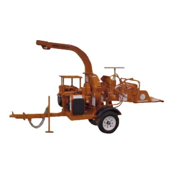
BRUSH CHIPPER
OPERATING & PARTS MANUAL
Model No: __________________
Serial No: __________________
DEALER:
Name: _____________________
Address: ___________________
City/State: __________________
Phone No: __________________
Delivery Date: _______________
Engine Make: _______________
Serial No: __________________
Clutch Make: ________________
Model: _________ S/N ________
PRINTED 4/02
BANDIT INDUSTRIES, INC.
REMUS, MICHIGAN, USA 49340
PHONE: (989) 561-2270 OR 561-2272
FAX: (989) 561-2273 ~ SALES DEPT.
FAX: (989) 561-2962 ~ PARTS/SERVICE
MODEL 65A
MODEL 65AW
65A & 65AW
MANUFACTURED BY
6750 Millbrook Road
®
Advertisement
Table of Contents
Troubleshooting

Related Manuals for Brush Bandit 65A


Summary of Contents for Brush Bandit 65A
- Page 1 OPERATING & PARTS MANUAL ATTENTION: Depending on what replacement parts you are ordering, we will need the following information: CHIPPER COMPONENTS 65A & 65AW Serial Number Model No: __________________ Model Number of Chipper Serial No: __________________ ENGINE COMPONENTS Engine Size...
- Page 15 1-02 FORM #WV-122 IT IS VERY IMPORTANT THAT THIS FORM IS FILLED OUT COMPLETELY & ACCURATELY. IF WE CANNOT READ THE PURCHASER’S INFORMATION OR IT IS INCORRECT, OUR CUSTOMER LIST WILL NOT BE ACCURATE. IMPORTANT - THIS FORM MUST BE RETURNED TO THE Customer Data Department 6750 Millbrook Road CUSTOMER DATA DEPARTMENT WITHIN TEN (10)
- Page 16 5-01 FORM #Q-104 DATE PURCHASED: _________________ TO BE RETURNED AFTER THIRTY (30) DAYS OF OPERATION MODEL: ___________________________ Please return to: Customer Data Department SERIAL NUMBER: ___________________ 6750 Millbrook Road DEALER NAME: _____________________ Remus, MI 49340 ____________________________________ PH: (989) 561-2270 FAX (989) 561-2273 CHIPPER QUALITY REPORT All of the employees that build your equipment strive to manufacturer the very best quality product on the market.
- Page 17 MODELS 65A & 65AW TABLE OF CONTENTS TABLE OF CONTENTS PAGES INTRODUCTION & WARRANTY ...........2 SERIAL NUMBER LOCATIONS ............ 6 SAFETY PROCEDURES ............... 7 SAFETY DECALS ................11 AUTOFEED OPTIONS ..............19 CONTROLS .................22 START-UP PROCEDURES ............25 LUBRICATION ................28 MAINTENANCE ................29 HYDRAULIC SECTION ............
- Page 18 MODELS 65A & 65AW INTRODUCTION & WARRANTY INTRODUCTION The purpose of this manual is to provide the user with specifications and procedures for the operation, maintenance and repair of the BANDIT CHIPPER. As with any piece of equipment, safety should always be a constant thought while the machine is being operated, serviced or stored. In...
- Page 20 MODELS 65A & 65AW SERIAL NUMBER LOCATIONS TYPICAL CHIPPER SERIAL NUMBER AND/OR WORK ORDER NUMBER LOCATIONS 1. Belt shield 2. W/O # on top of tongue NOTE: The engine information is located on the 3. Hinged chipper hood under handle engine block.
- Page 21 MODELS 65A & 65AW SAFETY PROCEDURES SAFETY PROCEDURES DANGER This equipment is intended for use by personnel The words Danger, Warning, Caution, and who are experienced with similar equipment. Always Notice are used on the safety decals and throughout operate safely. It is also recommended that...
- Page 22 MODELS 65A & 65AW SAFETY PROCEDURES SAFETY PROCEDURES DANGER DANGER Always block the tires and the machine tongue Never reach into the infeed hopper area of the whenever the Bandit is unhooked for operation. DO chipper. There is never any reason to. If you have...
- Page 23 MODELS 65A & 65AW SAFETY PROCEDURES SAFETY PROCEDURES WARNING DANGER It is very important after you have operated a new Never feed any materials that might contain wires, machine for approximately an hour to shut down stones, nails, or other metal objects which may the machine and recheck all nuts and bolts.
- Page 24 MODELS 65A & 65AW SAFETY PROCEDURES SAFETY PROCEDURES DANGER DANGER Do not work inside the mouth of the chipper or Do not work on the machine if the engine is running around the feedwheels, until you have installed the with the clutch disengaged. A clutch can self engage...
- Page 25 MODELS 65A & 65AW SAFETY DECALS SAFETY DECALS DANGER DO NOT feed vine-like material into this machine unless you follow the rules: Do Not allow vine-like material to lay in front of infeed hopper! DO NOT allow vine-like material to trip or entangle with you or your clothing.
- Page 26 MODELS 65A & 65AW SAFETY DECALS DECAL LOCATIONS - MODEL 65A & 65AW THESE DECALS ARE FOR MACHINES BUILT AFTER 4-1-02 ALTHOUGH LOCATIONS MAY VARY, ALL DECALS MUST BE ON MACHINE DURING OPERATION IF ANY DECALS BECOME DAMAGED, REPLACE IMMEDIATELY.
- Page 27 MODELS 65A & 65AW SAFETY DECALS DECAL LOCATIONS - MODEL 65A & 65AW THESE DECALS ARE FOR MACHINES BUILT AFTER 4-1-02 Modifications and/or additions of decals to this list will happen. Consult chipper dealer or manufacturer for most current decal package.
- Page 28 MODELS 65A & 65AW SAFETY DECALS DECAL LOCATIONS - MODEL 65A & 65AW THESE DECALS ARE FOR MACHINES BUILT BEFORE 4-1-02 ALTHOUGH LOCATIONS MAY VARY, ALL DECALS MUST BE ON MACHINE DURING OPERATION IF ANY DECALS BECOME DAMAGED, REPLACE IMMEDIATELY.
- Page 29 MODELS 65A & 65AW SAFETY DECALS DECAL LOCATIONS - MODEL 65A & 65AW THESE DECALS ARE FOR MACHINES BUILT BEFORE 4-1-02 Modifications and/or additions of decals to this list will happen. Consult chipper dealer or manufacturer for most current decal package.
- Page 30 MODELS 65A & 65AW SAFETY DECALS DECAL LOCATIONS - MODEL 65A & 65AW THESE DECALS ARE FOR MACHINES BUILT BEFORE 4-1-02 ALTHOUGH LOCATIONS MAY VARY, ALL DECALS MUST BE ON MACHINE DURING OPERATION IF ANY DECALS BECOME DAMAGED, REPLACE IMMEDIATELY.
- Page 31 MODELS 65A & 65AW SAFETY DECALS DECAL LOCATIONS - MODEL 65A & 65AW THESE DECALS ARE FOR MACHINES BUILT BEFORE 4-1-02 Modifications and/or additions of decals to this list will happen. Consult chipper dealer or manufacturer for most current decal package.
- Page 32 MODELS 65A & 65AW SAFETY DECALS SAFETY DECALS Safety Decals located on your Bandit Chipper contain useful information to assist you in operating your equipment safely. Some of the decals on your machine and their location are shown in this section.
- Page 33 MODELS 65A & 65AW AUTOFEED OPTIONS AUTOFEED OPTIONS AUTOFEED SYSTEM When processing material through the chipper, the feed system will automatically stop when the engine drops below a preset RPM point. The engine is constantly being monitored by an adjustable electronic speed switch.
- Page 34 MODELS 65A & 65AW AUTOFEED OPTIONS TROUBLE SHOOTING GUIDE IF THE POWER TO CHECK THE FEED SOLENOID IS INCONSISTENT OR DOES NOT WORK, CHECK THE FOLLOWING WITH A MULTIMETER: MULTIMETER SET AT RX100 RANGE TP1 to TP5 0 ohms TP2 to TP6...
- Page 35 MODELS 65A & 65AW AUTOFEED OPTIONS TROUBLE SHOOTING GUIDE POSSIBLE CAUSES WHY AUTOFEED DOES NOT WORK OR IS INTERMITTENT: 1. Switch is not turned on. 2. Engine not coming back to full rated RPM. 3. Bad ON/OFF switch. 4. Bad or corroded fuse holder.
- Page 36 MODELS 65A & 65AW CONTROLS CONTROLS CORRECT OPERATION OF FEED CONTROL HANDLE PUSH TO FEEDING REVERSE FEEDING FOR ALL CHIPPERS DESIGNED TO BE “HAND FED”. IF YOU ARE IN THE AREA OF THE INFEED HOPPER, ALWAYS BE WITHIN EASY REACH OF AND PREPARED TO OPERATE THE FEED CONTROL HANDLE.
- Page 37 MODELS 65A & 65AW CONTROLS CONTROLS CONTROLS Models 65A & 65AW Basic Location of Controls and Adjustments LOCATION SHOWN NOT SHOWN 1. Foot Pad Jack Chipper Belts 2. Engine Controls, Adjusters Pump Sheave 3. Discharge Deflector Adjuster Motor Coupler 4. Swivel Discharge Optional Autofeed Control 5.
- Page 38 MODELS 65A & 65AW CONTROLS CONSULT THE ENGINE MANUFACTURER’S MANUAL FOR SPECIFIC CONTROLS FOR TYPICAL GASOLINE ENGINES 1)a. Ignition Switch: Turn the ignition switch key clockwise one stop (on position) to turn the electrical system on. The key should remain in the on position while the engine is running.
- Page 39 MODELS 65A & 65AW START-UP PROCEDURES START-UP PROCEDURES DAILY START UP CHECK LIST Each day before starting your machine these checks must be made: Observe all safety procedures, on decals and from manual. Wear all applicable safety equipment; hard hat, gloves, eye protection, ear protection, etc.
- Page 40 MODELS 65A & 65AW START-UP PROCEDURES START-UP PROCEDURES DANGER Do not let anyone operate or maintain this machine until they have thoroughly read this manual. You can purchase additional Bandit manuals for a nominal fee. WARNING Consult your engine manual for proper break-in procedures. Various engines require somewhat different procedures, but basically the engines need to operate at lower R.P.M.’s and loads for a specific time.
- Page 41 MODELS 65A & 65AW START-UP PROCEDURES BEFORE STARTING ENGINE, cont. NOTICE USE CORRECT KNIFE HARDWARE DO NOT use a size or style chipper knife, bolt or nut other than factory approved for this chipper - see manual. DO NOT over torque or under torque knife bolts and nuts - see manual.
- Page 42 MODELS 65A & 65AW LUBRICATION LUBRICATION ENGINE ............Follow original equipment manufacturers requirements for both changing filters and oils. CLUTCH ............Follow original equipment manufacturers requirements for both greasing and adjusting. Frequently adjust, and grease per PTO manufacturers manual. HYDRAULIC RESERVOIR TANK ....Completely change oil and flush tank annually.
- Page 43 MODELS 65A & 65AW MAINTENANCE SECTION MAINTENANCE SECTION WARNING WHEN YOU CHANGE CHIPPER KNIVES CHECK CHIPPER DISC ASSEMBLY FOR ELONGATED KNIFE BOLT HOLES, SECURE WELDS, TORQUED BOLTS, EXCESSIVE WEAR AND IMPACT CRACKS. IF A PROBLEM IS FOUND CONTACT CHIPPER MANUFACTURER, OR AUTHORIZED CHIPPER DEALER.
- Page 44 MODELS 65A & 65AW MAINTENANCE SECTION MAINTENANCE CHECK SHEET DAILY O.K. Repaired Check the condition of your knives. Check chipper hood hinge. Check hood lock pin and padlock. Check entire machine for loose parts or components. Check and/or adjust belt tension.
- Page 45 MODELS 65A & 65AW MAINTENANCE SECTION MAINTENANCE PROCEDURES CHECK ITEMS TO BE SERVICED PROCEDURE WEEK MONTH (Always Replace If Needed) Chipper Knives, Nuts Check tightness, wear, replace if needed Chipper Disc, Fan Blades Check for proper security, damage, wear Chipper Hood Hinge Operating correctly, not damaged, lubrica Hood Lock Pin &...
- Page 46 MODELS 65A & 65AW MAINTENANCE SECTION MAINTENANCE SECTION The Bandit is a very simple machine to maintain. If you will follow a regular scheduled preventative maintenance program you should have years of trouble free operation. DANGER Before attempting any type of maintenance disengage clutch, turn off engine, wait for the disc to come to a complete stop, install the disc lock pin, disconnect battery, and make sure the ignition key is in your possession.
- Page 47 MODELS 65A & 65AW MAINTENANCE SECTION DAILY MAINTENANCE (cont.) 14) Check the safety decals and engine gauge: 9) Check air cleaner or precleaner, clean or Replace if missing or damaged. Check the engine replace as necessary: manufacturer’s manual to make sure your chipper Clean or replace element following engine manual engine is running properly.
- Page 48 MODELS 65A & 65AW MAINTENANCE SECTION MONTHLY MAINTENANCE 1) Check hydraulic pressures on the feedwheel 5) Tire air pressure: system: Fill tires to rated tire capacity. Check, reset and maintain hydraulic feedwheel pressure setting to a maximum of 1500 P.S.I. This...
- Page 49 MODELS 65A & 65AW MAINTENANCE SECTION MAINTENANCE PROCEDURE FOR UNPLUGGING YOUR CHIPPER If your chipper is plugging, it is usually caused by allowing the engine to drop below required R.P.M.’s. This can be resolved by simply shutting the feedwheel off when the engine begins to lug down.
- Page 50 MODELS 65A & 65AW MAINTENANCE SECTION TIRE WEAR DIAGNOSTIC CHART Wear Pattern Cause Action Center Wear Over Inflation Adjust pressure to particular load per tire catalog Edge Wear Under Inflation Adjust pressure to particular load per tire catalog Side Wear...
- Page 51 MODELS 65A & 65AW HYDRAULIC SECTION HYDRAULIC SECTION TYPICAL HYDRAULIC RELIEF PRESSURE SETTINGS TYPICAL HYDRAULIC FLOWS AND RPM SETTINGS (Approximate, For Reference Only, Engine At Full RPM) DESCRIPTION 2-KNIFE Main Relief 1500 PSI Feedwheel 1500 PSI Hydraulic Pump GPM 3.25 Gallons Per Minute Feedwheel GPM 3.25 Gallons Per Minute...
- Page 52 MODELS 65A & 65AW HYDRAULIC SECTION HYDRAULIC SECTION THE BANDIT HYDRAULIC SYSTEM • Replace the hydraulic oil suction screen & The Bandit is equipped with a very efficient, simple hydraulic system. Each component is oil filter with each 400 hours of operation or 3 months.
- Page 53 MODELS 65A & 65AW HYDRAULIC SECTION HYDRAULIC PRESSURE ADJUSTMENT PROCEDURE FOR YOUR BANDIT CHIPPER. The relief valve is typically located internally in the control valve. Do not adjust this relief valve above 1500 PSI. The relief valve system is a simple spring tension design but small pieces of debris can stick the valve partially open which weakens the feedwheel power.
- Page 54 MODELS 65A & 65AW HYDRAULIC SECTION TROUBLE SHOOTING BEFORE ATTEMPTING ANY TYPE OF MAINTENANCE DISENGAGE CLUTCH, TURN OFF ENGINE, WAIT FOR THE DISC TO COME TO A COMPLETE STOP, INSTALL THE DISC LOCK PIN, DISCONNECT BATTERY, AND MAKE SURE THE IGNITION KEY IS IN YOUR POSSESSION.
- Page 55 MODELS 65A & 65AW HYDRAULIC SECTION CORRECTING HYDRAULIC PROBLEMS BEFORE ATTEMPTING ANY TYPE OF MAINTENANCE DISENGAGE CLUTCH, TURN OFF ENGINE, WAIT FOR THE DISC TO COME TO A COMPLETE STOP, INSTALL THE DISC LOCK PIN, DISCONNECT BATTERY, AND MAKE SURE THE IGNITION KEY IS IN YOUR POSSESSION.
- Page 56 MODELS 65A & 65AW CHIPPER SECTION CHIPPER SECTION Knives should be replaced in sets. These sets are UNDER NO SITUATION IS HEAL OF KNIFE TO BE determined by the amount of resharpening done to INSIDE EDGE OF MILLED POCKET! the knives. It should be reinstalled with another knife of comparable usage.
- Page 57 MODELS 65A & 65AW CHIPPER SECTION CHIPPER KNIVES Only Bandit knives and hardware are recommended for use in your Bandit chippers. Only then can you be assured of a quality product that fits and performs the best to the standards of excellence that is expected from the Bandit chipper.
- Page 58 MODELS 65A & 65AW FEEDWHEEL COUPLER SECTION PROPER PROCEDURE FOR INSTALLATION AND REMOVAL OF J.B. COUPLER AND TAPERED FEEDWHEEL MOTOR Proper Equipment Needed: Feedwheel motor with tapered shaft. A degreaser agent. 3/16” x 3/16” x 3/4” long key for feedwheel motor.
- Page 59 MODELS 65A & 65AW ELECTRICAL SECTION TYPICAL ELECTRICAL WIRING DIAGRAMS 4 Wire Main Cable Color Code 2 Wire Main Cable Color Code 6 Wire Main Cable Color Code Black B (Hot) Black B (Hot) Black B (Hot) White W (Ground)
- Page 60 MODELS 65A & 65AW REPLACEMENT PARTS SERVICE RECORD DATE DESCRIPTION AMOUNT Bandit PRINTED 4/02 PAGE 46...
- Page 61 MODELS 65A & 65AW REPLACEMENT PARTS REPLACEMENT PARTS SECTION Depending on what replacement parts you are ordering we will need the following information: ENGINE COMPONENTS CLUTCH COMPONENTS CHIPPER COMPONENTS Engine Size Name of Manufacturer Serial Number Engine Serial Number Serial Number Model Number of Chipper Engine Spec.
- Page 62 MODELS 65A & 65AW INFEED HOPPER COMPONENTS Bandit PRINTED 4/02 PAGE 48...
- Page 63 MODELS 65A & 65AW INFEED HOPPER COMPONENTS LOCATION PART NUMBER DESCRIPTION 626-0500-38 Infeed Hopper 30” Folding Pan Assembly 900-4902-29 Bottom Yoke Spring Adjuster 900-4900-04 Feedwheel Tension Spring 626-0500-39 Control Handle 900-3914-98 Feedwheel Hydraulic Motor 980-0124-98 Feedwheel Torque Arm 626-0002-72 Feedwheel Coupler...
- Page 64 MODELS 65A & 65AW CHIPPER COMPONENTS Knife Bolt Must Be Installed Through The Knife Nut As Shown!!! Bandit PRINTED 4/02 PAGE 50...
- Page 65 MODELS 65A & 65AW CHIPPER COMPONENTS LOCATION PART NUMBER DESCRIPTION 626-0500-69 Anvil Assembly 626-0001-47 Feedwheel Guard 3 a. 900-1905-42 Bearing Retainer Bolt 900-4900-32 Bearing Retainer Lock Washer 626-0001-71 Bearing Retainer 900-4901-19 Chipper Bearing Bolt 900-1904-13 Front Chipper Bearing 626-0000-66 Front Chipper Bearing Backer Plate 8 a.
- Page 66 MODELS 65A & 65AW HYDRAULIC COMPONENTS Hydraulic Hose From Pump Hydraulic Hose To Tank Sol. Bandit PRINTED 4/02 PAGE 52...
- Page 67 MODELS 65A & 65AW HYDRAULIC COMPONENTS LOCATION PART NUMBER PART NUMBER DESCRIPTION 65AW 626-0500-53 626-0500-73 Hydraulic Tank 900-3900-07 900-3900-07 Hydraulic Tank Strainer 3 a. 900-3900-10 900-3900-10 Hydraulic Tank Filter 900-3900-09 900-39000-09 Hydraulic Tank Filter Mount 900-3914-98 900-3914-98 Feedwheel Control Valve...
- Page 68 MODEL 65A FRAME & ACCESSORY COMPONENTS Bandit PRINTED 4/02 PAGE 54...
- Page 69 MODEL 65A FRAME & ACCESSORY COMPONENTS LOCATION PART NUMBER DESCRIPTION 1 a. 986-0500-26 2” Ball Coupler Standard 900-0501-47 2” Ball Bolt On Hitch (4 Bolt - Optional) 980-0501-48 2 1/2” Pintle Ring (4 Bolt - Optional) 2 a. 626-0002-91 Fender Mount 626-0003-78 Rear Fender Mount (Kohler &...
- Page 70 MODEL 65AW FRAME & ACCESSORY COMPONENTS Bandit PRINTED 4/02 PAGE 56...
- Page 71 MODEL 65AW FRAME & ACCESSORY COMPONENTS LOCATION PART NUMBER DESCRIPTION 1 a. 986-0500-26 2” Ball Bolt On Hitch Single Position (Standard) 900-5901-45 2” Ball Coupler (Croft - Optional) 900-5901-46 2 1/2” Pintle Ring (Croft - Optional) 2 a. 626-0001-70 Battery Box Mount 900-7900-01 Plastic Strap On Battery Box (Not Shown) 986-0501-89...
- Page 72 OTHER EQUIPMENT AVAILABLE FROM BANDIT INDUSTRIES, INC. FOR FURTHER INFORMATION ON AVAILABLE EQUIPMENT FROM BANDIT INDUSTRIES, INC. CONTACT YOU LOCAL BANDIT DEALER OR BANDIT INDUSTRIES, INC. DIRECTLY. 12”, 14”, 18”, 19” AND 24” TRACK CHIPPERS 18” AND 20” DRUM CHIPPERS RECYCLING EQUIPMENT Bandit PRINTED 4/02...
Need help?
Do you have a question about the 65A and is the answer not in the manual?
Questions and answers