
Related Manuals for AERMEC NRW Series


Summary of Contents for AERMEC NRW Series
- Page 1 Refrigeratori e pompe di calore acqua acqua Water to water chillers and heat pumps NRW NRW-H NRW-E R22 - R407C ISO 9001 - Cert. nº 0128/1 INRWPW Sostituisce il: 0203 Replace: 65579.12 / 0101 65579.16 AERMEC S.P.A.
- Page 3 GENERAL INFORMATION INFORMAZIONI GENERALI • FEATURES CARATTERISTICHE GENERALI • Descrizione dell’unità • Unit description Componenti principali • Main components Descrizione dei componenti • Component description Organi di regolazione • Controls Organi di sicurezza e di controllo • Safety and controls devices Accessori •...
- Page 4 AERMEC S.p.A. I-37040 Bevilacqua (VR) Italia – Via Roma, 44 Tel. (+39) 0442 633111 Telefax 0442 93730 – (+39) 0442 93566 NRW-H www.aermec.com - info@aermec.com modello: model: numero di serie: serial number: NRW NRW-H NRW NRW-H DICHIARAZIONE DI CONFORMITÀ DECLARATION OF CONFORMITY...
- Page 5 Aftersales Service immediately. AERMEC S.p.A. declina ogni responsabilità per qualsiasi AERMEC S.p.A. declines all responsibility for any damage danno dovuto ad un uso improprio della macchina, ad una whatsoever caused by improper use of the machine, and a...
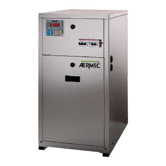
- Page 6 CARATTERISTICHE GENERALI SPECIFICATIONS Il refrigeratore della serie NRW monocompressore è The NRW series monocompressor chiller produces cold and un’unità per la produzione di acqua fredda e calda (pompa hot water (heat pump configuration) for public and techni- di calore) per impianti civili e tecnologici. L’installazione di cal systems.
- Page 7 DESCRIZIONE DEI COMPONENTI COMPONENT DESCRIPTION 1 COMPRESSORE 1 COMPRESSOR Compressori ermetici, con protezione termica incorporata, Hermetic compressors with incorporated heat protection; di tipo rotativo, scroll od alternativo a seconda dei modelli. rotary, scroll or reciprocating depending on model. 2 SCAMBIATORE (CIRCUITO ESTERNO) 2 HEAT EXCHANGER (EXTERNAL CIRCUIT) Del tipo a piastre in acciaio inox AISI 316, isolato esterna- Plate type exchanger in stainless steel AISI 316;...
- Page 8 16 QUADRO ELETTRICO 16 ELECTRICAL PANEL Contiene la sezione di potenza e la gestione dei controlli e Features the power section and management of safety devi- delle sicurezze (Standard IP 20). È conforme alle norme EN ces and controls (Standard IP 20). Complies with EN stan- 60335-2-40.
- Page 9 Azzeramento ore compressore; It is possible to connect the teminals 1-2 of M7 with an codice di accesso. external alert signal. The normally-opened contact is without Ai morsetti 1-2 di M7 è possibile collegare una segnalazione tension and can control a load of 250 V ~ 1A. esterna di Allarme.
- Page 10 La valvola d’inversione ciclo viene utilizzata nel cambio di The reversing valve is used to change Cooling/Heating ope- funzionamento Freddo/Caldo. ration of the unit. – GESTIONE DELLA VALVOLA SOLENOIDE DI BY-PASS – CONTROL OF THE BY-PASS SOLENOID VALVE BY THE DELLA PRESSOSTATICA (VSBP) PRESSURE VALVE (VSBP) Nel funzionamento a freddo dev’essere mantenuta chiusa.
- Page 11 nendo costante la temperatura di condensazione. The accessory is externally installable on floor units, which Ne è consigliabile l’impiego in tutte le installazioni per le feature a valve connected to the compressor gas line. quali sia disponibile acqua di pozzo o di acquedotto. To obtain the yield values with this accessory, refer to the Le versioni a pavimento sono predisposte per l’installazione evaporator version values.
- Page 12 DATI TECNICI • TECHNICAL DATA Mod. NRW ❆ Potenza frigorifera • Cooling capacity 10,8 ❆ Potenza assorbita totale * • Total input power * 1,93 1,852 2,73 2,47 ❆ Corrente assorbita A (230V) 9,3 12,7 16,8 Current absorption A (400V) – –...
- Page 13 10 H 12 H 10,5 13,85 13,95 22,9 21,9 28,05 26,57 38,29 36,4 3,10 3,52 3,57 5,82 7,69 11,47 11,6 15,8 – – – – – – – – 11,4 11,3 14,4 14,4 19,5 19,6 3,39 3,93 3,91 3,93 3,78 3,65 3,45 3,34...
- Page 14 DATI TECNICI • TECHNICAL DATA Mod. NRW ❆ Potenza frigorifera • Cooling capacity ❆ Potenza assorbita totale * • Total input power * ❆ Corrente assorbita A (230V) Current absorption A (400V) E.E.R. ❆ Portata acqua all’evaporatore • Evaporator water flow rate ❆...
- Page 15 10 E 12 E 5,25 10,5 13,6 22,2 27,3 37,9 2,95 14,5 17,7 – – – – – 12,4 14,3 20,2 2,68 3,18 3,58 3,31 3,29 3,16 1360 1810 2340 3820 4700 6520 – – – – – – 0,05 0,05 0,05 Rotativo...
- Page 16 DATI TECNICI • TECHNICAL DATA R407C Mod. NRW 27 H 37 H ❆ Potenza frigorifera • Cooling capacity 10,1 ❆ Potenza assorbita totale * • Total input power * 2,85 ❆ Corrente assorbita A (230V) 14,7 13,3 Current absorption A (400V) –...
- Page 17 57 H 77 H 107 H 127 H 13,2 13,3 21,5 20,6 26,4 36,4 34,6 3,75 12,1 12,2 16,2 – – – – – – – – 11,9 11,8 20,5 20,6 3,16 3,57 3,55 3,52 3,43 3,12 3,01 2,84 1740 2270 2290 3700...
- Page 18 DATI TECNICI • TECHNICAL DATA R407C Mod. NRW ❆ Potenza frigorifera • Cooling capacity ❆ Potenza assorbita totale * • Total input power * ❆ Corrente assorbita A (230V) Current absorption A (400V) E.E.R. ❆ Portata acqua all’evaporatore • Evaporator water flow rate ❆...
- Page 19 27 E 37 E 47 E 57 E 77 E 107 E 127 E 7,45 12,9 20,9 25,7 3,05 6,95 8,65 12,6 15,2 16,4 – – – – – 12,9 14,9 21,2 2,71 2,44 2,94 3,23 3,01 2,97 2,86 1280 1720 2220 3590...
- Page 20 USI IMPROPRI IMPROPER USES L'apparecchio è progettato e costruito per garantire la mas- The unit is designed and constructed to guarantee maximum sima sicurezza nelle sue immediate vicinanze. safety in its immediate proximity. L’apertura accidentale del quadro elettrico con macchina in Accidental opening of the electric switchboard with the funzione è...
- Page 21 CRITERI DI SCELTA SELECTION Le tabelle A, B e D riportano, per tutti i modelli, la potenza Tables A, B and D show the cooling capacity, the heating frigorifera, termica e l’assorbimento elettrico totale in fun- capacity and the total electrical absorption of all models, zione della temperatura dell’acqua all’uscita dal condensa- according to water temperature at the condenser and the tore e all’uscita dell’evaporatore.
- Page 22 La stessa tabella fornisce anche le portate d’acqua da invia- The same table also indicates the water flow to the two re ai due scambiatori per un ∆t pari a 5 °C, come nel caso exchangers for an ∆ t of 5 °C, as in the case being examined. in esame.
- Page 23 Heat exchanger inlet/outlet difference ( ∆ ∆ tc) (with condenser Differenza ingresso (∆ ∆ tc) uscita scambiatore (con funzione di condensatore): function): min: 5 min: 5 max: 15 max: 15 Differenza ingresso (∆ ∆ te) uscita scambiatore (con funzione Heat exchanger inlet/outlet difference ( ∆ ∆ te) (with evapora- di evaporatore): tor function): min: 3...
- Page 24 TAB A POTENZA FRIGORIFERA ED ASSORBIMENTO ELETTRICO TOTALI COOLING CAPACITY AND TOTAL INPUT POWER 10 H 12 H 5,07 5,07 8,23 7,73 10,9 10,6 14,06 14,16 23,23 22,22 28,9 26,95 41,46 37,3 1,71 1,71 2,32 2,06 2,56 2,53 2,82 2,86 4,75 4,74 9,85...
- Page 25 NRW 2 10 H 12 H 5,01 5,01 7,42 6,96 9,43 12,35 12,44 20,43 19,54 25,6 23,82 35,01 31,85 2,05 2,05 2,97 2,71 3,42 3,43 3,93 3,98 6,41 6,39 11,94 12,07 Qwe 861 1276 1198 1669 1621 2124 2140 3514 3360 4395 4098...
- Page 26 TAB B POTENZA FRIGORIFERA ED ASSORBIMENTO ELETTRICO TOTALI COOLING CAPACITY AND TOTAL INPUT POWER 37 H 47 H 57 H 77 H 107 H 127 H 5,53 7,73 7,33 10,2 10,2 13,40 13,50 21,81 20,90 27,20 25,36 39,41 35,46 1,68 2,42 2,17 2,64...
- Page 27 37 H 47 H 57 H 77 H 107 H 127 H 5,47 6,97 6,60 9,07 9,07 11,77 11,86 19,18 18,38 24,09 22,41 33,28 30,28 2,02 3,10 2,85 3,53 3,54 4,13 4,18 6,72 6,61 8,84 8,83 12,60 12,69 1198 1135 1561 1560 2025...
- Page 28 TAB C POTENZA FRIGORIFERA ED ASSORBIMENTO ELETTRICO TOTALI COOLING CAPACITY AND TOTAL INPUT POWER NRW 2 E 27 E 37 E 47 E 57 E 77 E 10 E 107 E 12 E 127 E 5,04 5,47 8,11 7,65 10,6 10,09 13,97 13,25 22,71 21,38 27,93 26,29 39,62 37,63 1,81 1,81...
- Page 29 NRW 2 E 27 E 37 E 57 E 77 E 10 E 107 E 12 E 127 E 4,43 4,81 6,51 6,14 9,03 11,21 10,63 18,59 17,50 22,86 21,52 30,54 29,01 2,48 2,48 3,66 3,78 4,02 4,14 5,05 8,21 8,52 10,18 10,61 12,52 13,15 Qwe 761...
- Page 30 TAB D POTENZA TERMICA ED ASSORBIMENTO ELETTRICO TOTALI HEATING CAPACITY AND TOTAL INPUT POWER NRW 2 H 27 H 37 H 47 H 57 H 77 H 10 H 107 H 12 H 127 H 6,75 7,06 10,16 9,96 12,32 12,01 16,76 16,5...
- Page 31 NRW 2 H 27 H 37 H 47 H 57 H 77 H 10 H 107 H 12 H 127 H 8,12 8,49 11,78 11,54 14,34 13,99 19,6 19,29 33,48 32,59 39,2 38,28 54,69 54,04 1,94 1,85 2,49 2,67 2,92 3,17 3,47 3,61...
- Page 32 TAV 1 PERDITE DI CARICO • PRESSURE DROPS SCAMBIATORE CIRCUITO ESTERNO NRW • NRW HEAT EXCHANGER (EXTERNAL CIRCUIT) kPa 100 9,5 m Portata acqua • Water flow TAV 2 PERDITE DI CARICO • PRESSURE DROPS SCAMBIATORE CIRCUITO UTENZE NRW E NRW-E 5 - 57 - 7 - 77 - 10 - 107 - 12 - 127 E SCAMBIATORI NRW H NRW AND NRW-E 5 - 57 - 7 - 77 - 10 - 107 - 12 - 127 HEAT EXCHANGER (INSTALLATION CIRCUIT) AND NRW H HEAT EXCHANGERS kPa 100...
- Page 33 TAV 3 PREVALENZA UTILE • EFFECTIVE PRESSURE CIRCUITO UTENZE NRW 2 - 27- 2E - 27E - 2 H 27H • NRW 2 - 27- 2E - 27E - 2 H 27H INSTALLATION CIRCUIT kPa 80 0,2 0,4 0,6 0,8 1,2 1,4 1,6 1,8 2 l/h x 1.000 Portata acqua •...
- Page 34 TAV 6 PERDITE DI CARICO FILTRO ACQUA • WATER FILTER PRESSURE DROPS Mod. NRW 2 - 27 3 - 37 4 - 47 5 - 57 7 - 77 10 - 107 12 - 127 ✔ ✔ ✔ 1” ✔ ✔...
- Page 35 TAB G PRESSIONE E POTENZA SONORA espressa in dB(A) SOUND PRESSURE AND POWER LEVEL rated in dB(A) Pressione sonora* Potenza sonora per frequenza centrale di banda (Hz) globale Sound pressure* Sound power band middle frequency (Hz) total Mod. 1.000 2.000 4.000 8.000 dB(A)
- Page 36 TAB L TABELLE DI CORREZIONE • CORRECTION TABLES Funzionamento con acqua glicolata FCGPF FCGPT FCGPA FCGQ FCGDP Operation with glycol 1,003 1,020 1,040 50 °C 1,005 1,060 1,110 1,010 1,130 1,250 0,99 0,996 1,012 1,124 7 °C 0,975 0,99 1,048 1,322 0,965 0,984...
- Page 37 TRASPORTO HANDLING Per il sollevamento dell'unità e il suo posizionamento in When lifting and positioning the unit on the work site, use a cantiere evitare di sollevare l’unità senza l’ausilio di carrelli lift truck or similar. elevatori o apparecchi similari. Extreme care must be taken in all the loading, unloading Particolare attenzione va posta a tutte le operazioni di cari- and lifting operations to avoid damage to the housing and...
- Page 38 Per le versioni NRW e NRW-E è obbligatoria l’installazione Failure to install the water filter supplied (6) with NRW del filtro acqua fornito a corredo (6), pena la decadenza and NRW-E versions will render the guarantee null and della garanzia. void.
- Page 39 La messa in funzione dev'essere preventivamente concorda- ta in base ai tempi di realizzazione dell'impianto. Prima dell'intervento del Servizio Assistenza AERMEC tutte le opere (allacciamenti elettrici e idraulici, caricamento e sfiato dell'aria dall'impianto) dovranno essere state ultimate.
- Page 40 Fig. 2 DIP SWITCH DIP SWITCH Solo Freddo Pompa di calore Cooling only Heat pump Dip Switch: Dip Switch: 1 OFF Uso interno 1 OFF Not used 2 OFF Uso interno 2 OFF Not used 3 OFF Uso interno 3 OFF Not used 4 OFF Ventilatore assiale 4 OFF Axial fan ON Ventilatore centrifugo...
- Page 41 DIMENSIONI • DIMENSIONS (mm) NRW 2 - 27 - 3 - 37 - 4 - 47 Gli attacchi idraulici degli NRW sono tutti da 1” Gas femmina tranne l’attacco del gruppo di caricamento (1/2” Gas femmina). NRW hydraulic fittings are 1” female Gas, with the exception of the charging assembly fitting (1/2”...
- Page 42 DIMENSIONI • DIMENSIONS (mm) NRW 5 - 57 - 7 - 77 - 10 - 107 - 12 - 127 Gli attacchi idraulici degli NRW sono tutti da 1” Gas maschio. NRW hydraulic fittings are all 1” male Gas. 2 7 8 Fori per cavi elettrici Electrical cable holes Mod.
- Page 43 SPAZI TECNICI MINIMI • MINIMUM TECHNICAL SPACE (mm) NRW 2 - 27 - 3 - 37 - 4 - 47 NRW 5 - 57 - 7 - 77 - 10 - 107 - 12 - 127...
- Page 44 DATI ACCESSORI • ACCESSORIES DATA (mm) PR - PANNELLO DI COMANDO A DISTANZA PR - REMOTE CONTROL PANEL VT - SUPPORTI ANTIVIBRANTI VT - ANTIVIBRATION PAD Mod. NRW 5 - 57 NRW 7 - 77 NRW 10 - 107 NRW 12 - 127...
- Page 45 LEGENDA PER CIRCUITO FRIGORIFERO • CHILLER CIRCUIT LEGEND = Accumulo • Storage tank = Pressostato di alta • High pressure switch = Pressostato di bassa • Low pressure switch = Circuito esterno • External circuit = Compressore • Compressor = Circuito utenze • Installation circuit = Filtro deidratatore •...
- Page 46 LAY-OUT CIRCUITO FRIGORIFERO E DISPOSITIVI DI CONTROLLO LAY-OUT OF CHILLER CIRCUIT AND CONTROL DEVICES Mod. NRW 2 E - 27 E - 3 E - 37 E - 4 E - 47 E VESP VSIC Mod. NRW 2 H - 27 H - 3 H - 37 H - 4 H - 47 H VESP Þ...
- Page 47 LAY-OUT CIRCUITO FRIGORIFERO E DISPOSITIVI DI CONTROLLO LAY-OUT OF CHILLER CIRCUIT AND CONTROL DEVICES Mod. NRW 5 - 57 - 7 - 77 - 10 - 107 - 12 - 127 * = solo per NRW 12 - 127 • only for NRW 12 - 127 Mod.
- Page 48 LEGENDA PER SCHEMI ELETTRICI • WIRING DIAGRAMS KEY = Pressostato di alta pressione = Porta seriale High pressure switch Serial connector = Pressostato di bassa pressione MPOE = Elettropompa Low pressure switch Electric pump = Contattore compressore = Magnetotermico circuito ausiliario Compressor contact maker Auxiliary circuit magneto-thermal cut-out = Condensatore di marcia...
- Page 49 SCHEMI ELETTRICI • WIRING DIAGRAMS COLLEGAMENTO ALIMENTAZIONE POWER CONNECTIONS NRW 2 - 27 - 3 - 37 - 4 - 47 (230 V) Gli schemi elettrici sono soggetti ad aggiornamento; è opportuno fare riferimento allo schema elettrico allegato all'apparecchio. Wiring diagrams may change for updating. It is therefore necessary to refer always to the wiring diagram inside the units.
- Page 50 SCHEMI ELETTRICI • WIRING DIAGRAMS COLLEGAMENTO ALIMENTAZIONE POWER CONNECTIONS NRW 3 - 37 - 4 - 47 (400 V) Gli schemi elettrici sono soggetti ad aggiornamento; è opportuno fare riferimento allo schema elettrico allegato all'apparecchio. Wiring diagrams may change for updating. It is therefore necessary to refer always to the wiring diagram inside the units.
- Page 51 SCHEMI ELETTRICI • WIRING DIAGRAMS COLLEGAMENTO ALIMENTAZIONE POWER CONNECTIONS NRW 5 - 7 - 10 - 12 57 - 77 - 107 - 127 Gli schemi elettrici sono soggetti ad aggiornamento; è opportuno fare riferimento allo schema elettrico allegato all'apparecchio. Wiring diagrams may change for updating.
- Page 52 SCHEMI ELETTRICI • WIRING DIAGRAMS COLLEGAMENTO QUADRO COMANDO E SICUREZZE CONTROL PANEL AND SAFETIES CONNECTIONS 15V 7 0V 6 NRW 2 - 27 - 3 - 37 - 4 - 47 15V 5 1 0V 0V 4 10V 3 2 10V 0V 2 24V 1 F 2A 250V...
- Page 53 SCHEMI ELETTRICI • WIRING DIAGRAMS COLLEGAMENTO QUADRO COMANDO E SICUREZZE CONTROL PANEL AND SAFETIES CONNECTIONS 15V 7 NRW 5 - 7 - 12 0V 6 15V 5 1 0V 0V 4 57 - 77 - 127 10V 3 2 10V 0V 2 24V 1 F 2A 250V...
- Page 54 SCHEMI ELETTRICI • WIRING DIAGRAMS COLLEGAMENTO QUADRO COMANDO E SICUREZZE CONTROL PANEL AND SAFETIES CONNECTIONS NRW 10 - 107 15V 7 0V 6 15V 5 1 0V 0V 4 10V 3 2 10V 0V 2 24V 1 F 2A 250V 1 +TAP 0V 2 24V 1...
- Page 55 SCHEMI ELETTRICI • WIRING DIAGRAMS COLLEGAMENTO QUADRO COMANDO E SICUREZZE CONTROL PANEL AND SAFETIES CONNECTIONS NRW 2 E - 27 E 15V 7 0V 6 15V 5 1 0V 0V 4 10V 3 2 10V 0V 2 24V 1 F 2A 250V 1 +TAP 0V 2 24V 1...
- Page 56 SCHEMI ELETTRICI • WIRING DIAGRAMS COLLEGAMENTO QUADRO COMANDO E SICUREZZE CONTROL PANEL AND SAFETIES CONNECTIONS 15V 7 NRW 5 E - 7 E - 12 E 0V 6 15V 5 1 0V 0V 4 57 E - 77 E - 127 E 10V 3 2 10V 0V 2...
- Page 60 Technical data shown in this booklet are not binding. gnativi. Aermec S.p.A. shall have the right to introduce at any time whatever L’Aermec S.p.A. si riserva la facoltà di apportare in qualsiasi momen- modifications deemed necessary to the improvement of the product.
Need help?
Do you have a question about the NRW Series and is the answer not in the manual?
Questions and answers