Table of Contents
Advertisement
Technical Description
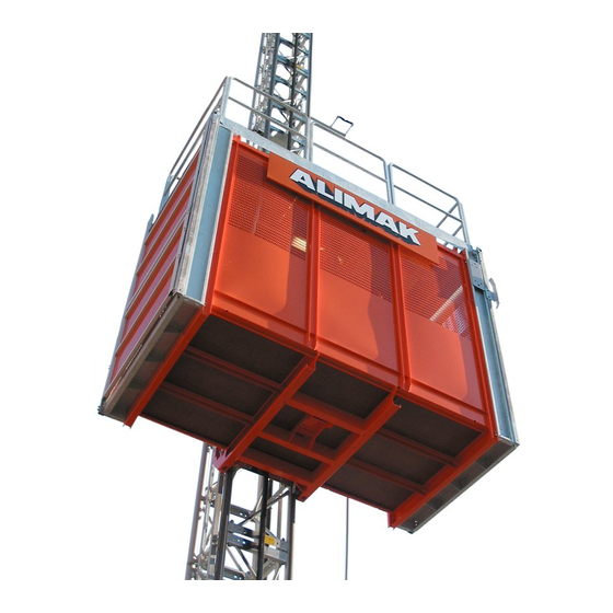
ALIMAK SCANDO 650
Construction Hoists
This manual is only applicable if the manufacturing number indicated below corresponds to the manufacturing number stamped on the identification
sign of the equipment. Where there is a conflict contact your ALIMAK representative.
YOUR HOIST HAS:
Part No. 9100272 - 1 03
Manufacturing No.:
Year:
2006 - 01 - 30
If the bottom right corner of this book is cut, the book is only valid for illustrative use!
Advertisement
Chapters
Table of Contents

Related Manuals for Alimak Scando 650 Series

Summary of Contents for Alimak Scando 650 Series
- Page 1 Construction Hoists This manual is only applicable if the manufacturing number indicated below corresponds to the manufacturing number stamped on the identification sign of the equipment. Where there is a conflict contact your ALIMAK representative. YOUR HOIST HAS: Part No. 9100272 - 1 03 Manufacturing No.:...
- Page 2 Photographs and drawings are illustrative only and do not necessarily show the design of the products on the market at any given point in time. The products must be used in conformity with applicable practice and safety regulations. Specifications of the products and equipment presented herein are subject to change without notice.
- Page 3 TECHNICAL DESCRIPTION TECHNICAL DATA & SPECIFICATIONS IMPORTANT SAFETY INSTRUCTIONS OPERATING INSTRUCTIONS SERVICE AND MAINTENANCE ELECTRIC TROUBLESHOOTING FOUNDATION HOIST MAST PREPARATIONS BEFORE INSTALLATION See Operator’s Manual for chapter C, D, E and F. Copyright © Alimak AB 2004. All rights reserved.
-
Page 5: Table Of Contents
Cable guiding device ........A 11 Control systems..........A 12 Landing equipment ........A 14 Safety equipment ..........A 16 Optional equipment........A 18 The purchaser’s / user’s own protective measures ........ A 24 Load signs............A 25 ALIMAK 34738 - 1/01... - Page 6 2.8 m car base structure (9’- 2 1/4’’) 3.5 m car base structure (11’- 5 3/4’’)
-
Page 7: General
IEC, CEE, EN, DIN, UL, CSA, SS etc. Necessary documents such as operator’s manual, wiring diagrams, circuit diagrams and spare parts lists are delivered with the hoist. ALIMAK 34739 - 1/02... -
Page 8: Foundation
The hoist can be used freestanding, bolted to the transportable sheet steel foundation or the concrete slab. With an additional buffer support the base frame also incorpo- rates a dual car set up. ALIMAK 34740 - 1/01... -
Page 9: Ground Enclosure
The enclosure is provided with one or two double-swing mechanically locked and electrically monitored door(s). Two entrance doors allow entrance to the car from 2 different directions. Doors can be positioned on any of the three sides away from mast. ALIMAK 34741 - 1/01... -
Page 10: Hoist Mast
Corresponding wall bracket can be installed either on slab ..or against wall a 210 Wall bracket bolt dimension is M24 Alimak original dia. 76 mm pivoted tube coupler ALIMAK 34742 - 1/02... - Page 11 Slutgränsbrytare bottom of the hoistway. upp / ner The final limit switch controls a main contactor, which switches off all three phases of the main power supply to the drive motor(s). Gränsbrytare upp / ner ALIMAK 34743 - 1/03...
-
Page 12: Car
The exit door can also be combined with a folding load ramp in 2 different versions; Manual folding load ramp . . . Manual folding load ramp Closed solid wall Car length extensions Full height entrance door ALIMAK 34744 - 1/01... - Page 13 The car length on each side of the mast shall be equal if possible. The difference may only be one extension section of 0.35 m (1’- 1 3/4’’). Although the hoist is asymmetrical it should be considered symmetrical and the longer end dictating the maximum allowable load. ALIMAK 34745 - 1/01...
- Page 14 SCANDO 650 construction hoists. Platform length adapted for different car lengths. The platform reach is approximately 2 times its own length. Payload capacity; 120 kg (265 lbs.). Patent pending. ALIMAK 34746 - 1/01...
-
Page 15: Drive Unit
– better (softer) riding comfort when starting and stopping. – better stopping accuracy. – less brake wear. – hoist speed can be reduced during installation and inspection procedures, which is not possible with direct on line (DOL) started electric motors. ALIMAK 34747 - 1/01... -
Page 17: Cable Guiding Device
Differential expansion/contraction of the power and control cable requires that the two trollies are not mechanically attached to each other. The method described above is also used for hoist installations in harsh surroundings with highwinds, low temperature etc. ALIMAK 34749 - 1/01... -
Page 18: Control Systems
The system is automatic, i.e. the car stops as soon as the joy-stick has been released (dead man type control) b – c) ALIMAK Lift Control ALC d 74 The ALC is a microprocessor based control with a main... - Page 19 Each landing is provided with two Call buttons, one for Up and Down resp. Push-button panels at landings The actual position and the hoist destination is shown on displays inside the car.On these displays a fault indica- tion is given. a 143 ALIMAK 34751 - 1/01...
-
Page 20: Landing Equipment
10-pole socket outlet and plug alternately, where ALC floor call selecting system occurs. The electric equipment is delivered with connection cable in lengths of 7 or 15 meter (23 or 49 ft.). Additional side protection ALIMAK 34752 - 1/01... - Page 21 Included electric material is of protection class IP 54 or higher. Accessories for landing run-offs. On site built landing run-off Vertical scaffold pipes parallel to the mast from the ground to the mast top attached outside the ground enclosure. ALIMAK 34753 - 1/03...
-
Page 22: Safety Equipment
The safety hooks are placed underneath the drive pinion of the machinery, preventing the hoist from falling off the mast should the drive pinion run off the top rack. ALIMAK 34754 - 1/01... - Page 23 Phase failure relay The electric equipment is protected by a phase failure relay, which means that the hoist can only be driven when correct phase sequence is connected. ALIMAK 34755 - 1/01...
-
Page 24: Optional Equipment
Coupling half on brake motor Axially movable lock ring to lock/release the centrifugal brake hub Brake lining ALIMAK 34756 - 1/01... - Page 25 When the rated load is exceeded the control circuit will be switched off to prevent the use of the hoist. At the same time a red LED lights. Indication light ”Overload” in car Fault code F4 will be displayed where ALC floor call selecting device occurs. ALIMAK 34757 - 1/01...
- Page 26 – Set the sheet steel plate onto the prepared gravel bed at its proper location. Alimak can supply manufacturing – Using a spirit level to locate the highest level guide pin. drawings of appropriate steel sheet foundation free of charge.
- Page 27 – Lift, lower and assemble the drive unit located on a mast section. – Connect the machinery to the hoist’s power and control circuits. Note; Hoist components such as ground enclosure not shown for clarity. ALIMAK 34759 - 1/01...
- Page 28 Car length Payload Freestandig During in operation erection* Hoist installed on 2 pce steel sheet foundation 3.2 m (10’- 6’’) 2000 kg (4400 lbs.) 22.5 meter, zone C 3.9 m (12’- 9 1/2’’) 4.6 m (15’- 1’’) ALIMAK 34760 - 1/01...
- Page 29 3.5 x 2.5 meter (11’- 5 ‘’ x 8’- 5’’). Concrete volume: 15 m (20 cu.yds). Please contact Alimak Calculation Department for advice. It may be desirable to connect three mast towers to each other. This is a preferable method to achieve greater height to increase the distance to the top tie.
-
Page 30: The Purchaser's / User's Own Protective Measures
Landings erected at site Landings built on site shall be equipped with safety railings and toe guards and shall meet applicable local regulations. Each landing shall be designed for the maximum load of the hoist. ALIMAK 34762 - 1/01... -
Page 31: Load Signs
The intention with showing this sign is to ensure personnel using the hoist and inspectors from the responsible authorities that the hoist is correctly installed according to the person responsible for the entire hoist installation. ALIMAK 34763 - 1/01... - Page 33 4 Technical data sheet .............B 6 Dimensions ..............B 7 Tie distance and overhang.........B 14 Lubrication and lubrication quantities ....B 14 Electric circuit diagram ..........B 14 Location of landing door/gate ........B 15 Tightening torque ............B 17 ALIMAK 34764 - 1/01...
-
Page 34: Product Range; Car Length 2.8 - 3.2 M
/ hydraulic or manual width 1.5 m exit door in two parts operated load ramp. possible location CA, CB or CC possible location A, B or C possible location A, B or C ALIMAK 34765 - 1/02... - Page 35 No. 1213 No. 1215 = 3.9 m Note: the doors can be located to meet site requirements. Closed, solid wall on exit side Additional section to increase car length 0.35 m on one or two sides j:\Order\430\43015\Prestanda\PrestandaScando650_Rev_J_xls. ALIMAK 34766 - 1/02...
- Page 36 / hydraulic or manual exit door in two parts width 1.5 m width 3.2 m operated load ramp. possible location A, B or C pos. location CA, CB or CC possible location C possible location A, B or C ALIMAK 34767 - 1/02...
- Page 37 = 4.6 m No. 1219 No. 1221 Note: the doors can be located to meet site requirements. Closed, solid wall on exit side Additional section to increase car length 0.35 m on one or two sides j:\Order\430\43015\Prestanda\PrestandaScando650_Rev_J_xls. ALIMAK 34768 - 1/02...
-
Page 39: Technical Data Sheet
SCANDO 650 FC .. /39 – 46 ext. (0.9 m/s) ..No. 1219 SCANDO 650 FC .. /35 – 39 (1.1 m/s)..No. 1220 SCANDO 650 FC .. /39 – 46 ext. (1.1 m/s) ..No. 1221 ALIMAK 34770 - 1/02... -
Page 40: Dimensions
(11’- 10 3/4’’) (624 lbs.) 1040 3900 mm 4310 mm 307 kg (3’- 5’’) (12’- 9 1/2’’) (14’- 1 3/4’’) (677 lbs.) 4600 mm 5010 mm 331 kg (15’- 1’’) (16’- 5 1/4’’) (730 lbs.) 1740 (5’- 8 1/2’’) ALIMAK 34771 - 1/01... - Page 41 4.6 m (15’- 1’’) 4700 mm (15’- 5’’) b 61 * exclusive of drive unit and safety railing 2336 (7’- 8’’) Minimum shaft dimensions: Min. permissible “clearence” on all external dimensions is 100 mm (4 in.) ALIMAK 34772 - 1/02...
- Page 42 * Add additional 0.1 m (4’’) where accessories for pipe support equipment are added to the ground enclosure. Add 0.1 + 0.1 m if added on both sides. Door opening 1500 mm (4’- 11’’) 4280 (14’- 0 1/2’’) Door opening 1500 mm (4’- 11’’) (4’’) 100 ALIMAK 34773 - 1/01...
- Page 43 5120 mm (16’- 9 1/2’’) 2545 mm (8’- 4 1/4’’) * Add additional 0.1 m (4’’) where accessories for pipe support equipment are added to the ground enclosure. Add 0.1 + 0.1 m if added on both sides. ALIMAK 34774 - 1/01...
- Page 44 Scale 1 : 40 approx. 450 mm (1’- 5 3/4’’) c/c pipe 1750 (5’- 9’’) (5’- 0 1/4’’) 1530 (3’- 9 1/4’’) 1150 1495 Weight: 60 kg (132 lbs.) (4’- 10 3/4’’) approx. 770 mm (2’- 6 1/4’’) ALIMAK 34775 - 1/01...
- Page 45 2845 (9’- 4’’) 1360 (4’- 5 1/2’’) Horizontal sliding gates for landings For installation ON slab Scale 1 : 40 Over all length E Opening G 1100 (3’- 7 1/4’’) b 75 Slab 625 (2’- 0 1/2’’) ALIMAK 34776 - 1/01...
- Page 46 Vertical sliding exit door with folding ramp – el. operated, EN Approved Scale 1 : 40 Width: internal 1400 mm (4’- 7’’) Weight: 280 kg (620 lbs.) 1100 (3’- 7 1/4’’) b 77 (2’- 5’’) 1000 (3’- 3 1/4’’) ALIMAK 34777 - 1/01...
-
Page 47: Tie Distance And Overhang
See lubrication diagram in the chapter "Service and Mainten- ance" Electric circuit diagram See hoist document box. Noise level at operation Measuring standard: IEC 651. Less than 85 dB(A). Operating temperature range + 40°C / – 25°C (+ 140°F / – 13°F). ALIMAK 34778 - 1/01... -
Page 48: Location Of Landing Door/Gate
2600 (8’- 6 1/4’’) (15’- 1’’) Alt.2 ø 76 (3’’) 2395 ( 7’- 10 1/4’’) Alt.3 ø 76 (3’’) 3340 (10’- 11 1/2’’) Alt.4 – 2800 – 3000 (9’- 2 1/4 – 9’- 10’’) (see corresp. figure) ALIMAK 34779 - 1/01... - Page 49 (4’’ – 11 3/4’’) (10 1/2’’) (1’’) [L 6 = add 500 – 700 mm to half car length [L 6 add 1040 mm (3’- 5’’) to half car length] (1’- 7 3/3’’ – 2’- 3 1/2’’)] ALIMAK 34780 - 1/01...
-
Page 50: Tightening Torque
Tightening torque Recommendations according to the chart on the following page apply in general except for: ALIMAK Mast bolt, dim. 1 ”UNC – Torque 350 Nm (258 lbf x ft) – Spanner size 1 1/2” ALIMAK Scaffold clamp Ø 76 mm –... - Page 51 – dry surface. Dimension Spanner size Torque lbf x ft 10 mm 13 mm M 10 17 mm M 12 19 mm M 14 22 mm M 16 24 mm M 20 30 mm M 24 36 mm ALIMAK 34782 - 1/01...
- Page 52 No 1202 E Febr. -05. S S C C A A N N D D O O 6 6 5 5 0 0 M M o o d d u u l l a a r r S S y y s s t t e e m Dual motor machinery (DOL) Weight 495 kg Vertical exit door...
- Page 53 1.0 kg/meter where cable basket occurs. Add additional 147 kg or 117 kg respectively, where optional load ramp occurs. Add additional 0.1 m where accessories for pipe support equipment are added to the ground enclosure. ALIMAK AB, P O Box 720, SE-931 27 Skellefteå, Sweden. Tel. +46 910 87000. Fax +46 910 56690. E-mail: info@alimak.se. Web site: www.alimak.com.
- Page 54 No 1204 E Febr. -05. S S C C A A N N D D O O 6 6 5 5 0 0 M M o o d d u u l l a a r r S S y y s s t t e e m Dual motor machinery (DOL) Weight 495 kg Vertical exit door...
- Page 55 1.0 kg/meter where cable basket occurs. Add additional 147 kg or 117 kg respectively, where optional load ramp occurs. Add additional 0.1 m where accessories for pipe support equipment are added to the ground enclosure. ALIMAK AB, P O Box 720, SE-931 27 Skellefteå, Sweden. Tel. +46 910 87000. Fax +46 910 56690. E-mail: info@alimak.se. Web site: www.alimak.com.
- Page 56 No 1203 E Febr. -05. S S C C A A N N D D O O 6 6 5 5 0 0 M M o o d d u u l l a a r r S S y y s s t t e e m Dual motor machinery (DOL) Weight 495 kg Vertical exit door...
- Page 57 1.0 kg/meter where cable basket occurs. Add additional 147 kg or 117 kg respectively, where optional load ramp occurs. Add additional 0.1 m where accessories for pipe support equipment are added to the ground enclosure. ALIMAK AB, P O Box 720, SE-931 27 Skellefteå, Sweden. Tel. +46 910 87000. Fax +46 910 56690. E-mail: info@alimak.se. Web site: www.alimak.com.
- Page 58 No 1249 E Febr. -05. S S C C A A N N D D O O 6 6 5 5 0 0 M M o o d d u u l l a a r r S S y y s s t t e e m Dual motor machinery (DOL) Weight 495 kg Vertical exit door...
- Page 59 1.0 kg/meter where cable basket occurs. Add additional 147 kg or 117 kg respectively, where optional load ramp occurs. Add additional 0.1 m where accessories for pipe support equipment are added to the ground enclosure. ALIMAK AB, P O Box 720, SE-931 27 Skellefteå, Sweden. Tel. +46 910 87000. Fax +46 910 56690. E-mail: info@alimak.se. Web site: www.alimak.com.
- Page 60 No 1250 E Febr. -05. S S C C A A N N D D O O 6 6 5 5 0 0 M M o o d d u u l l a a r r S S y y s s t t e e m Dual motor machinery (DOL) Weight 495 kg Vertical exit door...
- Page 61 1.0 kg/meter where cable basket occurs. Add additional 147 kg or 117 kg respectively, where optional load ramp occurs. Add additional 0.1 m where accessories for pipe support equipment are added to the ground enclosure. ALIMAK AB, P O Box 720, SE-931 27 Skellefteå, Sweden. Tel. +46 910 87000. Fax +46 910 56690. E-mail: info@alimak.se. Web site: www.alimak.com.
- Page 62 No 1205 E Febr. -05. S S C C A A N N D D O O 6 6 5 5 0 0 M M o o d d u u l l a a r r S S y y s s t t e e m Dual motor machinery (DOL) Weight 495 kg Vertical exit door...
- Page 63 1.0 kg/meter where cable basket occurs. Add additional 147 kg or 117 kg respectively, where optional load ramp occurs. Add additional 0.1 m where accessories for pipe support equipment are added to the ground enclosure. ALIMAK AB, P O Box 720, SE-931 27 Skellefteå, Sweden. Tel. +46 910 87000. Fax +46 910 56690. E-mail: info@alimak.se. Web site: www.alimak.com.
- Page 64 No 1206 E Febr. -05. S S C C A A N N D D O O 6 6 5 5 0 0 M M o o d d u u l l a a r r S S y y s s t t e e m Dual motor machinery (FC) incl.
- Page 65 1.0 kg/meter where cable basket occurs. Add additional 147 kg or 117 kg respectively, where optional load ramp occurs. Add additional 0.1 m where accessories for pipe support equipment are added to the ground enclosure. ALIMAK AB, P O Box 720, SE-931 27 Skellefteå, Sweden. Tel. +46 910 87000. Fax +46 910 56690. E-mail: info@alimak.se. Web site: www.alimak.com.
- Page 66 No 1208 E Febr. -05. S S C C A A N N D D O O 6 6 5 5 0 0 M M o o d d u u l l a a r r S S y y s s t t e e m Dual motor machinery (FC) incl.
- Page 67 1.0 kg/meter where cable basket occurs. Add additional 147 kg or 117 kg respectively, where optional load ramp occurs. Add additional 0.1 m where accessories for pipe support equipment are added to the ground enclosure. ALIMAK AB, P O Box 720, SE-931 27 Skellefteå, Sweden. Tel. +46 910 87000. Fax +46 910 56690. E-mail: info@alimak.se. Web site: www.alimak.com.
- Page 68 No 1254 E Febr. -05. S S C C A A N N D D O O 6 6 5 5 0 0 M M o o d d u u l l a a r r S S y y s s t t e e m Dual motor machinery (FC) incl.
- Page 69 1.0 kg/meter where cable basket occurs. Add additional 147 kg or 117 kg respectively, where optional load ramp occurs. Add additional 0.1 m where accessories for pipe support equipment are added to the ground enclosure. ALIMAK AB, P O Box 720, SE-931 27 Skellefteå, Sweden. Tel. +46 910 87000. Fax +46 910 56690. E-mail: info@alimak.se. Web site: www.alimak.com.
- Page 70 No 1210 E Febr. -05. S S C C A A N N D D O O 6 6 5 5 0 0 M M o o d d u u l l a a r r S S y y s s t t e e m Dual motor machinery (FC) incl.
- Page 71 Add additional 147 kg or 117 kg respectively, where optional load ramp occurs. Add additional 0.1 m where accessories for pipe support equipment are added to the ground enclosure. ALIMAK AB, P O Box 720, SE-931 27 Skellefteå, Sweden. Tel. +46 910 87000. Fax +46 910 56690. E-mail: info@alimak.se. Web site: www.alimak.com.
- Page 72 No 1211 E Febr. -05. S S C C A A N N D D O O 6 6 5 5 0 0 M M o o d d u u l l a a r r S S y y s s t t e e m Dual motor machinery (FC) incl.
- Page 73 Add additional 147 kg or 117 kg respectively, where optional load ramp occurs. Add additional 0.1 m where accessories for pipe support equipment are added to the ground enclosure. ALIMAK AB, P O Box 720, SE-931 27 Skellefteå, Sweden. Tel. +46 910 87000. Fax +46 910 56690. E-mail: info@alimak.se. Web site: www.alimak.com.
- Page 74 No 1255 E Febr. -05. S S C C A A N N D D O O 6 6 5 5 0 0 M M o o d d u u l l a a r r S S y y s s t t e e m Dual motor machinery (FC) incl.
- Page 75 1.0 kg/meter where cable basket occurs. Add additional 147 kg or 117 kg respectively, where optional load ramp occurs. Add additional 0.1 m where accessories for pipe support equipment are added to the ground enclosure. ALIMAK AB, P O Box 720, SE-931 27 Skellefteå, Sweden. Tel. +46 910 87000. Fax +46 910 56690. E-mail: info@alimak.se. Web site: www.alimak.com.
- Page 76 No 1212 E Febr. -05. S S C C A A N N D D O O 6 6 5 5 0 0 M M o o d d u u l l a a r r S S y y s s t t e e m Triple motor machinery incl.
- Page 77 Add additional 147 kg or 117 kg respectively, where optional load ramp occurs. Add additional 0.1 m where accessories for pipe support equipment are added to the ground enclosure. ALIMAK AB, P O Box 720, SE-931 27 Skellefteå, Sweden. Tel. +46 910 87000. Fax +46 910 56690. E-mail: info@alimak.se. Web site: www.alimak.com.
- Page 78 No 1213 E Febr. -05. S S C C A A N N D D O O 6 6 5 5 0 0 M M o o d d u u l l a a r r S S y y s s t t e e m Triple motor machinery incl.
- Page 79 Add additional 147 kg or 117 kg respectively, where optional load ramp occurs. Add additional 0.1 m where accessories for pipe support equipment are added to the ground enclosure. ALIMAK AB, P O Box 720, SE-931 27 Skellefteå, Sweden. Tel. +46 910 87000. Fax +46 910 56690. E-mail: info@alimak.se. Web site: www.alimak.com.
- Page 80 No 1214 E Febr. -05. S S C C A A N N D D O O 6 6 5 5 0 0 M M o o d d u u l l a a r r S S y y s s t t e e m Triple motor machinery incl.
- Page 81 Add additional 147 kg or 117 kg respectively, where optional load ramp occurs. Add additional 0.1 m where accessories for pipe support equipment are added to the ground enclosure. ALIMAK AB, P O Box 720, SE-931 27 Skellefteå, Sweden. Tel. +46 910 87000. Fax +46 910 56690. E-mail: info@alimak.se. Web site: www.alimak.com.
- Page 82 No 1215 E Febr. -05. S S C C A A N N D D O O 6 6 5 5 0 0 M M o o d d u u l l a a r r S S y y s s t t e e m Triple motor machinery incl.
- Page 83 Add additional 147 kg or 117 kg respectively, where optional load ramp occurs. Add additional 0.1 m where accessories for pipe support equipment are added to the ground enclosure. ALIMAK AB, P O Box 720, SE-931 27 Skellefteå, Sweden. Tel. +46 910 87000. Fax +46 910 56690. E-mail: info@alimak.se. Web site: www.alimak.com.
- Page 84 No 1218 E Febr. -05. S S C C A A N N D D O O 6 6 5 5 0 0 M M o o d d u u l l a a r r S S y y s s t t e e m Triple motor machinery incl.
- Page 85 Add additional 147 kg or 117 kg respectively, where optional load ramp occurs. Add additional 0.1 m where accessories for pipe support equipment are added to the ground enclosure. ALIMAK AB, P O Box 720, SE-931 27 Skellefteå, Sweden. Tel. +46 910 87000. Fax +46 910 56690. E-mail: info@alimak.se. Web site: www.alimak.com.
- Page 86 No 1219 E Febr. -05. S S C C A A N N D D O O 6 6 5 5 0 0 M M o o d d u u l l a a r r S S y y s s t t e e m Triple motor machinery incl.
- Page 87 Add additional 147 kg or 117 kg respectively, where optional load ramp occurs. Add additional 0.1 m where accessories for pipe support equipment are added to the ground enclosure. ALIMAK AB, P O Box 720, SE-931 27 Skellefteå, Sweden. Tel. +46 910 87000. Fax +46 910 56690. E-mail: info@alimak.se. Web site: www.alimak.com.
- Page 88 No 1220 E Febr. -05. S S C C A A N N D D O O 6 6 5 5 0 0 M M o o d d u u l l a a r r S S y y s s t t e e m Triple motor machinery incl.
- Page 89 Add additional 147 kg or 117 kg respectively, where optional load ramp occurs. Add additional 0.1 m where accessories for pipe support equipment are added to the ground enclosure. ALIMAK AB, P O Box 720, SE-931 27 Skellefteå, Sweden. Tel. +46 910 87000. Fax +46 910 56690. E-mail: info@alimak.se. Web site: www.alimak.com.
- Page 90 No 1221 E Febr. -05. S S C C A A N N D D O O 6 6 5 5 0 0 M M o o d d u u l l a a r r S S y y s s t t e e m Triple motor machinery incl.
- Page 91 Add additional 147 kg or 117 kg respectively, where optional load ramp occurs. Add additional 0.1 m where accessories for pipe support equipment are added to the ground enclosure. ALIMAK AB, P O Box 720, SE-931 27 Skellefteå, Sweden. Tel. +46 910 87000. Fax +46 910 56690. E-mail: info@alimak.se. Web site: www.alimak.com.
- Page 93 FOUNDATION Foundation ............Concrete slab........... Foundation pit..........Concrete slab without foundation frame..Transportable foundation ......Load on the foundation ........Ground pressure ..........G 10 ALIMAK 34783 - 1/01...
-
Page 95: Foundation
– part no. 9021 586-000 for mast section c/c 650 x 900 (2’-1 5/8’’ x 2’-11 7/16’’) The foundation may be made in any of the following ways, depending upon the finished concrete level compared with the ground level. ALIMAK 34784 - 1/01... - Page 96 This alternative requires draining. Min. 100 mm (4’’) gravel Drain pipe with outlet IMPORTANT: Please note that the foundation must always be isolated, or the surrounding soil prevented from freezing, if there is a risk of frost heave. ALIMAK 34785 - 1/01...
- Page 97 Note that a concrete slab which forms part of a foundation pit does not require this extra reinforcement. 1800 (2’’) (5’- 10 3/4’’) Ø 10 s 200 SCANDO single car SCANDO dual cars Cross-section of concrete slab Extra reinforcement Normal reinforcement ALIMAK 34786 - 1/01...
- Page 98 The concrete must reach 70% of the required compressive strength before the installation of the hoist may start. This is usually obtained 7 days after placing the concrete. If a shorter time is needed, higher strength concrete may be used. ALIMAK 34787 - 1/01...
- Page 99 – (14’- 10 1/4’’) (7.02 cu.yds) 1.5 x 4.6 5350 2195 2035 – 4530 7.27 (4’-11’’ x 15’-1’’) (3’-1 3/4’’) (17’- 6 3/4’’) (7’- 2 1/2’’) (1’- 3’’) (6’- 8’’) – (14’- 10 1/4’’) (9.51 cu.yds) ALIMAK 34788 - 1/01...
- Page 100 See picture below. H min. = 1060 mm (3’-5 3/4’’) Stairs, bridges or fill materials Structure for raising the enclosure Ground level Alternatively a concrete pit can be made below ground level. Ground level ALIMAK 34789 - 1/01...
-
Page 101: Foundation Pit
Vertical reinforcement to be fixed all around the slab 2. When the base slab has cured, add the horizontal reinforce- ment, followed by formwork and completion of the walls of the foundation pit. ALIMAK 34790 - 1/01... -
Page 102: Concrete Slab Without Foundation Frame
Transportable foundation In order to use a transportable steel foundation, the following requirements must be met: – The steel foundation must conform to all of Alimak’s specifi- cations. (These can be ordered separately from an Alimak representative). – The type of installation must be approved by the local gover- ning authorities. -
Page 103: Load On The Foundation
Dynamic load approx. 2 x 2200 kg + 2/3 x (2775 + 2050)kg 7617 kg 16792 lbs. ∑ = 37936 kg 83632 lbs. 37936 x 9.81 = 372152 N. In round figures = 372 kN (83632 lbs.) ALIMAK 34792 - 1/01... -
Page 104: Ground Pressure
Should the ground be able to stand higher pressures, it is possible to increase the load on the foundation. Please contact ALIMAK for information. Examples of acceptable ground pressure according to SBN 1975 (Swedish Building Norms): Moraine = 0.4 –... - Page 105 1.6 x P v σ ground = (MPa) D 1 x W 3 x 1000 1.6 x 509 σ ground = 3.95 x 4.53 x 1000 σ ground = 0.045 MPa (MPa x 145 = 6.60 psi) ALIMAK 34794 - 1/01...
- Page 107 HOIST MAST Projecting hoist mast........Mast ties............Tied hoist mast..........Reaction forces..........Attachment of ties........... H 20 ALIMAK 34795 - 1/03...
-
Page 109: Projecting Hoist Mast
The selection of ties depends also on the length of tie required tie distance. For detailed specifications see heading ”Mast ties”. 4. Numbers of mast ties Determined by tie distance and overhang at various maximum lifting height. See tables in the end of chapter. ALIMAK 34796 - 1/01... - Page 110 As can be seen from the following tables this is only necessary at extremely high lifting heights. In such cases turn to Alimak Calculation Department who can optimize the installation so that as few reinforced mast sections as possible need to be used.
- Page 111 A transition section or a reinforced mast section must always be used for connection against bottom frame. A transition section must always be used between mast sections with different tube thicknesses. Reinforced mast sections must always be placed at the bottom of a mast installation. ALIMAK 34798 - 1/01...
-
Page 112: Mast Ties
If you intend to use embedment anchorings, these must be prepared well in advance before erection. Note that the wall must always be dimensioned to take up the reaction forces of the ties. ALIMAK 34799 - 1/01... -
Page 113: Tied Hoist Mast
If this is not possible an extra tie should be instal- led at the landing. – In cases where required lifting height exceeds the max. allowable mast height, we kindly ask you to contact Alimak for advice. ALIMAK 34800 - 1/03... -
Page 114: Reaction Forces
2001 – 3000 kg – – – – 16.4 19.0 21.2 26.4 (a = b / 2) – – – – (13.5) (5.3) (15.6 ) (5.3 ) (18.2 ) (4.5 ) (20.8 ) (4.1 ) ALIMAK 34801 - 1/03... - Page 115 16.4 16.6 17.3 17.5 22.7 11.0 between 2001 – 3000 kg – – (a = b / 2) – – (11.0) (11.2) – – (11.8 ) (12.0 ) (14.8 ) (10.1 ) (22.7 ) (11.0 ) ALIMAK 34935 - 1/03...
- Page 117 They can never be less. Values for distances above last mast tie larger than b / 2 can be interpolated. Note: The most favourable reaction forces will always appear at mast tie distances = 12 m (40 ft.). ALIMAK 34802 - 1/01...
- Page 118 4000 1600 – 3200 34 kN 39 kN 9100636-120 – ” – – 3200 33 kN 37 kN * Note: Wall bracket turned for installation towards face of structure will give additional 75 mm (3 in.). ALIMAK 34803 - 1/02...
- Page 119 Rx and Ry according to the table on page H6. P must never exceed P max stated for each size of mast tie according to table above. Each scaffold clamp must include a bolt and nut at the end of the tube as indicated. ALIMAK 34804 - 1/01...
- Page 120 4900 2450 – 3200 11 kN 12 kN – ” – 1600 – 2800 10 kN 11 kN * Note: Wall bracket turned for installation towards face of structure will give additional 75 mm (3 in.). ALIMAK 34805 - 1/02...
- Page 121 P must never exceed P max indicated for each size of mast tie according to table above. B min. – B max. Each scaffold clamp must see table include a bolt and nut at the end of the tube as indicated. ALIMAK 34806 - 1/01...
- Page 122 P must never exceed P max indicated for each size of mast tie according to table on previous page. Values stated in brackets ( ) in the following tables indicates maximum allowable force P max with tube couplers applied OUTSIDE the vertical scaffold tubes. ALIMAK 34807 - 1/03...
- Page 123 – ” – 5575 1600 – 1500 – ” – 37 kN (60 kN) 42 kN (68 kN) – ” – – ” – 1100 – 3200 – ” – 18 kN (32 kN) 20 kN (36 kN) ALIMAK 34808 - 1/03...
- Page 124 – ” – 5925 1600 – 1500 – ” – 35 kN (60 kN) 40 kN (68 kN) – ” – – ” – 1100 – 3200 – ” – 17 kN (28 kN) 20 kN (32 kN) ALIMAK 348912 - 1/03...
- Page 125 – ” – 6275 1600 – 1500 – ” – 33 kN (59 kN) 37 kN (67 kN) – ” – – ” – 1100 – 3200 – ” – 10 kN (26 kN) 18 kN (29 kN) ALIMAK 348913 - 1/03...
- Page 126 86 kN 97 kN – ” – 3390 3780 1420 9102800-310 71 kN 80 kN – ” – 3690 4380 1720 9102800-360 68 kN 76 kN – ” – 4290 4980 2020 9102800-430 66 kN 74 kN ALIMAK 34809 - 1/03...
- Page 127 Rx and Ry according to the table on page H6. P must never exceed P max indicated for each size of mast tie according to table on previous page. L min. – L max. see table ALIMAK 34810 - 1/03...
-
Page 128: Attachment Of Ties
350 mm ( 1’- 1 3/4’’) Wall bracket P/N 9101019-000 Hole dia. 26 mm for bolt dimension M24 c/c between bolts 890 mm ( 2’- 11’’). Height between hole rows = 110 mm (4 1/4’’). ALIMAK 34811 - 1/01... - Page 129 Calculation of tie forces. Geographical region according to European Stormwind map. Conclusion: Forces in top tie do normally increase when free, untied mast top is increased. Table shows that the reaction forces generally increase when recommended tie intervals decrease. ALIMAK 34812 - 1/01...
- Page 130 The maximum allowable payload on all the landings combined is shown on the diagram to the right. The load is understood to be equally distributed on the respective landing run-offs. ALIMAK 34813 - 1/01...
- Page 131 – Exception must also be granted for personnel to call the hoist. – Landing equipment for vertical pipes should be avoided at lifting heights greater than 100 m (330 ft.). ALIMAK 34814 - 1/01...
- Page 133 PREPARATIONS BEFORE INSTALLATION General ............Permission ............Erection place..........Foundation ............Delivery check-up ........... Arrangement of power supply...... Client’s power supply........Power supply from generator set at jobsite Voltage drop in the power supply ....ALIMAK 34732 - 1/01...
-
Page 135: Permission
Should there be any damage, report the same to the responsible transportation insurance company within 7 days from the date of arrival of the goods. Other claims should be made to ALIMAK representative within the same period. ALIMAK 34733 - 1/01... -
Page 136: Arrangement Of Power Supply
Note: If an earth leakage circuit breaker, ELCB, (ground fault circuit breaker) is to be used, the trip-out value should be chosen for equipment protection i.e. 500mA. Use of 30mA ELCB is not recommended as it continuously trips due to the motor starting current. ALIMAK 34734 - 1/01... - Page 137 Minimum size of the supply cable is shown on the table above. The table refers to supply voltage 400V to 460V, 50/60Hz. See note re: earth circuit breaker on previous page. ALIMAK 34735 - 1/01...
-
Page 138: Power Supply From Generator Set At Jobsite I
A amperes at rated voltage. If this is not possible, the guidelines below can be used. For DOL starting of Alimak hoists having 1 or 2 drive motors we suggest the following generator sizes: – 1 motor drive size 132M, 13 kW (15 kW) 100 kVA min. - Page 139 5. Use some sort of soft start equipment. If you have any questions regarding the power supply cables or the trailing cables, please contact Alimak for advice. Conversion table mm to AWG AWG No.
Need help?
Do you have a question about the Scando 650 Series and is the answer not in the manual?
Questions and answers
Не поднимается, что делать?
If the Alimak Scando 650 Series does not lift when starting in the Up direction, follow these steps:
1. Check if the contactors oscillate on and off ("shatter") when starting with a full load.
2. Inspect the contacts of the Up and main contactors for damage.
3. Measure the incoming power supply voltage at both the B-panel at the base and the M-panel in the car during starting conditions with a rated load.
4. Determine if the voltage drop exceeds acceptable values.
5. If a voltage drop issue is identified, increase the conductor size in the power supply cable from the job site distribution.
These steps help diagnose and resolve voltage drop problems affecting the hoist's operation.
This answer is automatically generated