Lenovo ThinkCentre M710q Hardware Maintenance Manual
Hide thumbs
Also See for ThinkCentre M710q:
- User manual and hardware maintenance manual (53 pages) ,
- User manual (60 pages)
Table of Contents
Advertisement
Advertisement
Table of Contents

Related Manuals for Lenovo ThinkCentre M710q


Summary of Contents for Lenovo ThinkCentre M710q
- Page 1 M710q Hardware Maintenance Manual Machine Type: 10YC...
- Page 2 Important safety information” on page v and Appendix D “Notices” on page 69. First Edition (September 2018) © Copyright Lenovo 2018. LIMITED AND RESTRICTED RIGHTS NOTICE: If data or software is delivered pursuant to a General Services Administration “GSA” contract, use, reproduction, or disclosure is subject to restrictions set forth in Contract No. GS-...
-
Page 3: Table Of Contents
Lenovo Support Web site ..Chapter 4. Security ..15 Lenovo Web site... . . Attaching a Kensington-style cable lock .. - Page 4 Export classification notice ..Battery recycling information for the European Union ....Electronic emissions notices ..Federal Communications Commission (FCC) Appendix C.
-
Page 5: About This Manual
Important: This manual is intended only for trained service technicians who are familiar with ThinkCentre computers. Use this manual along with the advanced diagnostic tests to troubleshoot problems effectively. Before servicing a ThinkCentre computer, be sure to read and understand “Read this first: Important safety information” on page v. © Copyright Lenovo 2018... - Page 6 M710q Hardware Maintenance Manual...
-
Page 7: Read This First: Important Safety Information
Reading and understanding all the safety information reduces the risk of personal injury and damage to your product. If you no longer have a copy of the Safety, Warranty, and Setup Guide, you can obtain a Portable Document Format (PDF) version from the Lenovo Support Web site at http://www.lenovo.com/UserManuals... - Page 8 • When lifting any heavy object: 1. Ensure you can stand safely without slipping. 2. Distribute the weight of the object equally between your feet. 3. Use a slow lifting force. Never move suddenly or twist when you attempt to lift. 4.
-
Page 9: Electrical Safety
Remember: There must be a complete circuit to cause electrical shock. By observing the above rule, you may prevent a current from passing through your body. – When using a tester, set the controls correctly and use the approved probe leads and accessories for that tester. © Copyright Lenovo 2018... -
Page 10: Safety Inspection Guide
– Stand on suitable rubber mats (obtained locally, if necessary) to insulate you from grounds such as metal floor strips and machine frames. Observe the special safety precautions when you work with very high voltages; these instructions are in the safety sections of maintenance information. Use extreme care when measuring high voltages. •... -
Page 11: Handling Electrostatic Discharge-Sensitive Devices
– Use the round ground-prong of the ac plug on ac-operated computers. Grounding requirements Electrical grounding of the computer is required for operator safety and correct system function. Proper grounding of the electrical outlet can be verified by a certified electrician. © Copyright Lenovo 2018... -
Page 12: Safety Notices (Multi-Lingual Translations)
Safety notices (multi-lingual translations) The caution and danger safety notices in this section are provided in the following languages: • English • Arabic • Brazilian/Portuguese • Chinese (simplified) • Chinese (traditional) • French • German • Hebrew • Italian • Korean •... - Page 13 Laser radiation when open. Do not stare into the beam, do not view directly with optical instruments, and avoid direct exposure to the beam. ≥18 kg (37 lb) ≥32 kg (70.5 lb) ≥55 kg (121.2 lb) CAUTION: Use safe practices when lifting. CAUTION: © Copyright Lenovo 2018...
- Page 14 The power control button on the device and the power switch on the power supply do not turn off the electrical current supplied to the device. The device also might have more than one power cord. To remove all electrical current from the device, ensure that all power cords are disconnected from the power source.
- Page 15 ≥18 kg (37 lb) ≥32 kg (70.5 lb) ≥55 kg (121.2 lb) xiii © Copyright Lenovo 2018...
- Page 16 PERIGO A corrente elétrica proveniente de cabos de alimentação, de telefone e de comunicações é perigosa. Para evitar risco de choque elétrico: • Não conecte nem desconecte nenhum cabo ou execute instalação, manutenção ou reconfiguração deste produto durante uma tempestade com raios. •...
- Page 17 Radiação a laser quando aberto. Não olhe diretamente para o feixe a olho nu ou com instrumentos ópticos e evite exposição direta ao feixe. ≥18 kg (37 lb) ≥32 kg (70.5 lb) ≥55 kg (121.2 lb) CUIDADO: Utilize procedimentos de segurança para levantar equipamentos. © Copyright Lenovo 2018...
- Page 18 CUIDADO: O botão de controle de alimentação do dispositivo e o botão para ligar/desligar da fonte de alimentação não desligam a corrente elétrica fornecida ao dispositivo. O dispositivo também pode ter mais de um cabo de alimentação. Para remover toda a corrente elétrica do dispositivo, assegure que todos os cabos de alimentação estejam desconectados da fonte de alimentação.
- Page 19 © Copyright Lenovo 2018...
- Page 20 xviii M710q Hardware Maintenance Manual...
- Page 21 • Branchez sur des socles de prise de courant correctement câblés tout équipement connecté à ce produit. • Lorsque cela est possible, n'utilisez qu'une seule main pour connecter ou déconnecter les câbles d'interface. • Ne mettez jamais un équipement sous tension en cas d'incendie ou d'inondation, ou en présence de dommages matériels. © Copyright Lenovo 2018...
- Page 22 • Avant de retirer les carters de l'unité, mettez celle-ci hors tension et déconnectez ses cordons d'alimentation, ainsi que les câbles qui la relient aux réseaux, aux systèmes de télécommunication et aux modems (sauf instruction contraire mentionnée dans les procédures d'installation et de configuration). •...
- Page 23 Pour mettre l'unité hors tension, vous devez déconnectertous les cordons de la source d'alimentation. VORSICHT An Netz-, Telefon- und Datenleitungen können gefährliche Spannungen anliegen. Aus Sicherheitsgründen: • Bei Gewitter an diesem Gerät keine Kabel anschließen oder lösen. Ferner keine Installations-, Wartungs- oder Rekonfigurationsarbeiten durchführen. © Copyright Lenovo 2018...
- Page 24 • Gerät nur an eine Schutzkontaktsteckdose mit ordnungsgemäß geerdetem Schutzkontakt anschließen. • Alle angeschlossenen Geräte ebenfalls an Schutzkontaktsteckdosen mit ordnungsgemäß geerdetem Schutzkontakt anschließen. • Die Signalkabel nach Möglichkeit einhändig anschließen oder lösen, um einen Stromschlag durch Berühren von Oberflächen mit unterschiedlichem elektrischem Potenzial zu vermeiden. •...
- Page 25 Mit dem Netzschalter an der Einheit und am Netzteil wird die Stromversorgung für die Einheit nicht unterbrochen. Die Einheit kann auch mit mehreren Netzkabeln ausgestattet sein. Um die Stromversorgung für die Einheit vollständig zu unterbrechen, müssen alle zum Gerät führenden Netzkabel vom Netz getrennt werden. xxiii © Copyright Lenovo 2018...
- Page 26 xxiv M710q Hardware Maintenance Manual...
- Page 27 PERICOLO La corrente elettrica proveniente dai cavi di alimentazione, del telefono e di comunicazione può essere pericolosa. Per evitare il rischio di scosse elettriche: © Copyright Lenovo 2018...
- Page 28 • Non collegare o scollegare qualsiasi cavo oppure effettuare l'installazione, la manutenzione o la riconfigurazione del prodotto durante un temporale. • Collegare tutti i fili elettrici a una presa di alimentazione correttamente cablata e dotata di messa a terra. • Collegare alle prese elettriche appropriate tutte le apparecchiature che verranno utilizzate per questo prodotto.
- Page 29 Il pulsante di controllo dell'alimentazione presente sull'unità e l'interruttore dell'alimentatore non disattivano l'alimentazione corrente fornita all'unità. E' possibile che l'unità disponga di più cavi di alimentazione. Per disattivare l'alimentazione dall'unità, accertarsi che tutti i cavi di alimentazione siano scollegati dalla fonte di alimentazione. xxvii © Copyright Lenovo 2018...
- Page 30 xxviii M710q Hardware Maintenance Manual...
- Page 31 • Cualquier equipo que se conecte a este producto también debe conectarse a tomas de corriente debidamente cableadas. • Siempre que sea posible, utilice una sola mano para conectar o desconectar los cables de señal. xxix © Copyright Lenovo 2018...
- Page 32 • No encienda nunca un equipo cuando hay señales de fuego, agua o daños estructurales. • Desconecte los cables de alimentación, los sistemas de telecomunicaciones, las redes y los módems conectados antes de abrir las cubiertas de los dispositivos, a menos que se indique lo contrario en los procedimientos de instalación y configuración.
- Page 33 Además, el dispositivo podría tener más de un cable de alimentación. Para suprimir toda la corriente eléctrica del dispositivo, asegúrese de que todos los cables de alimentación estén desconectados de la toma de corriente. xxxi © Copyright Lenovo 2018...
- Page 34 xxxii M710q Hardware Maintenance Manual...
-
Page 35: Chapter 1. Overview
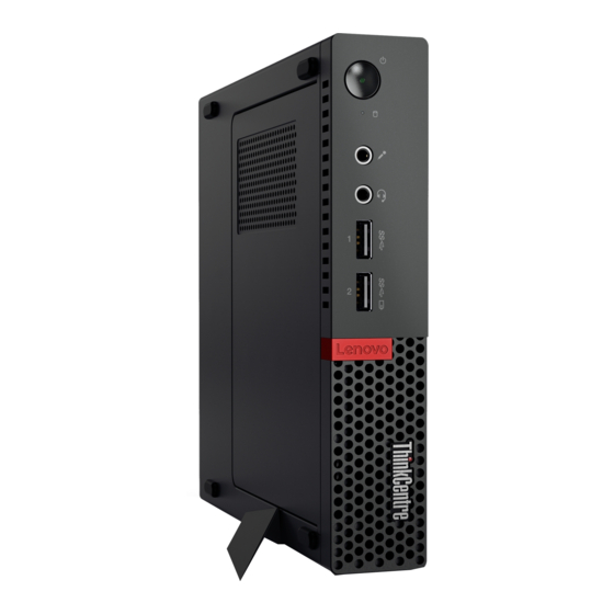
Note: Your computer model might look slightly different from the illustration. Figure 1. Front view Power indicator Power button Microphone connector Storage drive status indicator Headset connector USB 3.1 Gen 1 connector Always On USB 3.1 Gen 1 connector Illuminated red dot © Copyright Lenovo 2018... -
Page 36: Rear View
Power indicator This indicator is on when the computer is on. Power button Used to turn on your computer. When you cannot shut down the computer from the operating system, press and hold the power button for four or more seconds to turn off the computer. Storage drive status indicator This indicator is on when the storage drive is in use. - Page 37 Figure 2. Rear view Optional connector 1 Optional connector 2 Security-lock slot Wi-Fi antenna slot Ethernet connector USB 3.1 Gen 2 connectors (2) ® USB 3.1 Gen 1 connector DisplayPort 1.2 out connector DisplayPort 1.2 out connector USB 3.1 Gen 1 connector Power adapter connector Optional connector 2 Depending on the computer model, the connector might vary.
-
Page 38: System Board
Used to secure a Kensington-style cable lock. Wi-Fi antenna slot Used to install the rear Wi-Fi antenna cable connector that is available only on some models. The rear Wi-Fi antenna is installed on the rear Wi-Fi antenna cable connector. Ethernet connector Used to connect an Ethernet cable for network access. - Page 39 Figure 3. System board Serial connector 1 Serial connector 2 USB 3.1 Gen 1 connector Storage drive fan connector Microprocessor socket Coin-cell battery Illuminated red dot connector Internal speaker or advanced speaker connector Chapter 1 Overview...
-
Page 40: Machine Type And Model Label
M.2 storage drive slot Machine type and model label The machine type and model label identifies the computer. When you contact Lenovo for help, the machine type and model information helps support technicians to identify the computer and provide faster service. - Page 41 – Microphone connector Input/Output (I/O) features • Audio connectors (headset and microphone) • DisplayPort 1.2 out connectors • Ethernet connector • Serial connectors (optional) • USB connectors Expansion • Memory slots • M.2 solid-state drive slot Network features • Ethernet LAN •...
- Page 42 M710q Hardware Maintenance Manual...
-
Page 43: Chapter 2. Using The Computer
Lenovo for help. In addition, some locations offer extended privileges and services to registered users. To register the computer with Lenovo, ensure that the computer is connected to the Internet. Then, go to http://www.lenovo.com/register and follow the instructions on the screen. - Page 44 M710q Hardware Maintenance Manual...
-
Page 45: Chapter 3. You And Your Computer
Where it is impossible to avoid reflections or to adjust the lighting, an antiglare filter placed over the screen might be helpful. However, these filters might affect the clarity of the image on the screen; try them only after you have exhausted other methods of reducing glare. © Copyright Lenovo 2018... -
Page 46: Air Circulation
Accessibility information Lenovo is committed to providing users who have hearing, vision, and mobility limitations with greater access to information and technology. This section provides information about the ways these users can get the most out of their computer experience. You also can get the most up-to-date accessibility information from the following Web site: http://www.lenovo.com/accessibility... -
Page 47: Cleaning The Computer
Documentation in accessible formats Lenovo provides electronic documentation in accessible formats, such as properly tagged PDF files or HyperText Markup Language (HTML) files. Lenovo electronic documentation is developed to ensure that visually impaired users can read the documentation through a screen reader. -
Page 48: Good Maintenance Practices
If the local electrical outlet style is different from the type you are currently using, contact the Lenovo Customer Support Center to purchase either an electrical plug adapter or a new power cord. See “Calling for service” on page 55. -
Page 49: Chapter 4. Security
The cable lock also locks the buttons used to open the computer cover. This is the same type of lock used with many notebook computers. You can order such a cable lock directly from Lenovo by searching for Kensington at: http://www.lenovo.com/support Figure 5. - Page 50 M710q Hardware Maintenance Manual...
-
Page 51: Chapter 5. Troubleshooting
If these troubleshooting instructions do not resolve your problem, continue with the next step. 3. If the problem with Ethernet cable, keyboard, mouse, power cord, power adapter, or VESA mount bracket persists, contact the Lenovo Customer Support Center. For a list of Lenovo Support phone numbers, go to http://www.lenovo.com/support/phone . -
Page 52: Screen Problems
Solutions: • Ensure that all cables and cords are securely connected to the computer and connected devices. • Ensure that when the computer is on, the fan grill is not blocked (there is air flow around the grill), and the fans are working. -
Page 53: Serial Connector Cannot Be Accessed
Serial connector cannot be accessed Solutions: • Connect the serial cable to the serial connector on the computer and to the serial device. If the serial device has its own power cord, connect the power cord to a grounded electrical outlet. •... - Page 54 M710q Hardware Maintenance Manual...
-
Page 55: Chapter 6. Replacing Hardware
• When installing or replacing an option, use the appropriate instructions explained in this manual along with the instructions that come with the option. • In most areas of the world, Lenovo requires the return of defective CRUs. Information about this will come with the CRU or will come a few days after the CRU arrives. -
Page 56: Knowing Frus (Including Crus)
You must remove the screws and panel to access the specific CRU. Optional-service CRUs can be removed and installed by users or, during the warranty period, by a Lenovo service technician. Before replacing FRUs Before replacing any FRU, read the following: •... -
Page 57: Locating Frus (Including Crus)
Locating FRUs (including CRUs) Notes: • Some of the components are optional. • To replace , and , contact a Lenovo service technician. For a list of Lenovo Support phone numbers, go to . To replace other parts, contact Amazon http://www.lenovo.com/support/phone Helpdesk. -
Page 58: Replacing The Keyboard Or Mouse
Self-service CRUs Optional-service CRUs Non-CRUs Power adapter Internal speaker Microprocessor Power cord System fan Coin-cell battery Computer cover Storage drive Illuminated red dot cable Bottom cover Storage drive bracket Advanced speaker Memory module Wi-Fi card shield Antenna bracket M.2 solid-state drive Wi-Fi card System board ®... - Page 59 Figure 8. Removing the power adapter Figure 9. Removing the power cord Chapter 6 Replacing hardware...
-
Page 60: Replacing The Vesa Mount Bracket
Figure 10. Installing the power cord Figure 11. Installing the power adapter Replacing the VESA mount bracket Attention: Do not open the computer or attempt any repair before reading and understanding “Read this first: Important safety information” on page v in this document. 1. -
Page 61: Removing The Computer Cover
Figure 12. Removing the VESA mount bracket Figure 13. Installing the VESA mount bracket Removing the computer cover Attention: Do not open the computer or attempt any repair before reading and understanding “Read this first: Important safety information” on page v in this document. CAUTION: Before you open the computer cover, turn off the computer and wait several minutes until the computer is cool. -
Page 62: Replacing The Storage Drive
Figure 14. Removing the dust shield Figure 15. Removing the computer cover Replacing the storage drive Note: The storage drive is optional. Attention: Do not open the computer or attempt any repair before reading and understanding “Read this first: Important safety information” on page v in this document. 1. - Page 63 Figure 16. Removing the storage drive bracket Figure 17. Removing the storage drive Figure 18. Installing the storage drive Chapter 6 Replacing hardware...
-
Page 64: Replacing The Internal Speaker
Figure 19. Installing the storage drive bracket 4. Connect the storage drive cable to the system board. 5. Complete the replacement. See “Completing the parts replacement” on page 53. Replacing the internal speaker Attention: Do not open the computer or attempt any repair before reading and understanding “Read this first: Important safety information”... -
Page 65: Replacing The System Fan
Figure 21. Installing the internal speaker 4. Connect the internal speaker cable to the internal speaker connector on the system board. 5. Complete the replacement. See “Completing the parts replacement” on page 53. Replacing the system fan Attention: Do not open the computer or attempt any repair before reading and understanding “Read this first: Important safety information”... -
Page 66: Replacing The Wi-Fi Card
Figure 23. Installing the system fan 7. Connect the system fan cable to the system fan connector on the system board. 8. Install the illuminated red dot cable to the new system fan. 9. Complete the replacement. See “Completing the parts replacement” on page 53. Replacing the Wi-Fi card Attention: Do not open the computer or attempt any repair before reading and understanding “Read this first: Important safety information”... - Page 67 Figure 25. Disconnecting the Wi-Fi antennas Figure 26. Removing the Wi-Fi card Figure 27. Installing the Wi-Fi card Figure 28. Connecting the Wi-Fi antennas Chapter 6 Replacing hardware...
-
Page 68: Replacing The Bottom Cover
Figure 29. Installing the Wi-Fi card shield 4. Complete the replacement. See “Completing the parts replacement” on page 53. Replacing the bottom cover Attention: Do not open the computer or attempt any repair before reading and understanding “Read this first: Important safety information” on page v in this document. 1. -
Page 69: Replacing The Memory Module
Figure 31. Installing the bottom cover 3. Complete the replacement. See “Completing the parts replacement” on page 53. Replacing the memory module Attention: Do not open the computer or attempt any repair before reading and understanding “Read this first: Important safety information” on page v in this document. If your computer supports one memory module, install the module into the DIMM 1 slot. -
Page 70: Replacing The M.2 Solid-State Drive
Figure 33. Removing the memory module Figure 34. Installing the memory module Figure 35. Closing the memory module retainer 4. Complete the replacement. See “Completing the parts replacement” on page 53. Replacing the M.2 solid-state drive Attention: Do not open the computer or attempt any repair before reading and understanding “Read this first: Important safety information”... -
Page 71: Replacing The Illuminated Red Dot Cable
3. Replace the M.2 solid-state drive. Figure 36. Unlocking the M.2 solid-state drive clip Figure 37. Removing the M.2 solid-state drive Figure 38. Installing the M.2 solid-state drive Figure 39. Locking the M.2 solid-state drive clip 4. Complete the replacement. See “Completing the parts replacement” on page 53. Replacing the illuminated red dot cable Attention: Do not open the computer or attempt any repair before reading and understanding “Read this first: Important safety information”... -
Page 72: Replacing The Advanced Speaker
2. Disconnect the illuminated red dot cable from the system board. 3. Replace the illuminated red dot cable. Figure 40. Removing the illuminated red dot cable Figure 41. Installing the illuminated red dot cable 4. Disconnect the illuminated red dot cable from the system board. 5. -
Page 73: Replacing The Wi-Fi Antennas
Figure 42. Removing the advanced speaker Figure 43. Installing the advanced speaker 5. Connect the advanced speaker cable to the advanced speaker connector on the system board. 6. Complete the replacement. See “Completing the parts replacement” on page 53. Replacing the Wi-Fi antennas Note: Remove the rear Wi-Fi antenna cover before installing the computer into the TIO monitor model: Tiny- in-One 23- Monitor (MT: 10DQ). - Page 74 Figure 44. Disconnecting the front Wi-Fi antenna cable from the Wi-Fi card Figure 45. Removing the front Wi-Fi antenna Figure 46. Installing the front Wi-Fi antenna M710q Hardware Maintenance Manual...
- Page 75 Figure 47. Connecting the front Wi-Fi antenna cable to the Wi-Fi card 4. Complete the replacement. See “Completing the parts replacement” on page 53. Replacing the rear Wi-Fi antenna 1. Remove the computer cover. See “Removing the computer cover” on page 27. 2.
- Page 76 Figure 49. Removing the antenna cover that secures the rear Wi-Fi antenna cable Figure 50. Removing the rear Wi-Fi antenna cable Figure 51. Installing the rear Wi-Fi antenna cable Figure 52. Installing the antenna cover to secure the rear Wi-Fi antenna cable M710q Hardware Maintenance Manual...
-
Page 77: Replacing The Storage Drive Cable
Figure 53. Installing the rear Wi-Fi antenna 5. Connect the rear Wi-Fi antenna cable to the Wi-Fi card. 6. Complete the replacement. See “Completing the parts replacement” on page 53. Replacing the storage drive cable Attention: Do not open the computer or attempt any repair before reading and understanding “Read this first: Important safety information”... -
Page 78: Replacing The Heat Sink
Replacing the heat sink Attention: Do not open the computer or attempt any repair before reading and understanding “Read this first: Important safety information” on page v in this document. CAUTION: The heat sink might be very hot. Turn off the computer and wait three to five minutes to let the computer cool before removing the computer cover. -
Page 79: Replacing The Microprocessor
Figure 58. Installing the heat sink Figure 59. Tightening the screws to secure the heat sink 6. Complete the replacement. See “Completing the parts replacement” on page 53. Replacing the microprocessor Attention: Do not open the computer or attempt any repair before reading and understanding “Read this first: Important safety information”... - Page 80 • Do not drop anything onto the microprocessor socket while it is exposed. The socket pins must be kept as clean as possible. Figure 60. Unlocking the microprocessor socket retainer Figure 61. Pivoting the microprocessor socket upward Figure 62. Removing the microprocessor M710q Hardware Maintenance Manual...
- Page 81 Figure 63. Installing the microprocessor Chapter 6 Replacing hardware...
-
Page 82: Replacing The Coin-Cell Battery
Figure 64. Pivoting the microprocessor socket downward Figure 65. Locking the microprocessor socket retainer 7. Complete the replacement. See “Completing the parts replacement” on page 53. Replacing the coin-cell battery Attention: Do not open the computer or attempt any repair before reading and understanding “Read this first: Important safety information”... - Page 83 Your computer has a special type of memory that maintains the date, time, and settings for built-in features, such as parallel connector assignments (configurations). A coin-cell battery keeps this information active when you turn off the computer. The coin-cell battery normally requires no charging or maintenance throughout its life; however, no coin-cell battery lasts forever.
-
Page 84: Replacing The Antenna Bracket
Figure 68. Installing the coin-cell battery Figure 69. Pressing the coin-cell battery downward 6. Complete the replacement. See “Completing the parts replacement” on page 53. To dispose of the coin-cell battery, refer to the “Lithium coin-cell battery notice” topic in the Safety and Warranty Guide. -
Page 85: Replacing The System Board And Chassis
Figure 70. Removing the antenna bracket Figure 71. Installing the antenna bracket 6. Complete the replacement. See “Completing the parts replacement” on page 53. Replacing the system board and chassis Attention: Do not open the computer or attempt any repair before reading and understanding “Read this first: Important safety information”... - Page 86 Note: Carefully handle the system board by its edges. Figure 72. Removing the screws that secure the system board Figure 73. Removing the system board Figure 74. Installing the system board M710q Hardware Maintenance Manual...
-
Page 87: Completing The Parts Replacement
Figure 75. Installing the screws to secure the system board 16. Route all the cables that you disconnected from the failing system board, and then reconnect the cables to the new system board. See “System board” on page 4. 17. Complete the replacement. See “Completing the parts replacement” on page 53. Completing the parts replacement After completing the installation or replacement for all parts, Complete the replacement. - Page 88 Figure 77. Reinstalling the dust shield 4. Install the screw to secure the computer cover. 5. Place the computer in an upright position. 6. If a locking device is available, use it to lock the computer. 7. Reconnect the external cables and power cords to the corresponding connectors on the computer. M710q Hardware Maintenance Manual...
-
Page 89: Chapter 7. Getting Information, Help, And Service
Information resources You can use the information in this section to access useful resources relating to your computing needs. Accessing other manuals All latest electronic manuals are available on the Lenovo Support Web site at: http://www.lenovo.com/support Lenovo Support Web site ®... -
Page 90: Using Other Services
These items are not covered by the warranty: • Replacement or use of parts not manufactured for or by Lenovo or non-warranted Lenovo parts • Identification of software problem sources • Configuration of BIOS as part of an installation or upgrade •... -
Page 91: Appendix A. Regulatory Information
• Connect the equipment into an outlet on a circuit different from that to which the receiver is connected. • Consult an authorized dealer or service representative for help. Lenovo is not responsible for any radio or television interference caused by using other than recommended cables and connectors or by unauthorized changes or modifications to this equipment. Unauthorized changes or modifications could void the user’s authority to operate the equipment. - Page 92 EU wireless module declarations are available at following Internet addresse: http://www.lenovo.com/eu-doc-desktops Lenovo cannot accept responsibility for any failure to satisfy the protection requirements resulting from a non-recommended modification of the product, including the installation of option cards from other manufacturers.
-
Page 93: Eurasian Compliance Mark
Klasse B. Dieses Gerät ist berechtigt, in Übereinstimmung mit dem Deutschen EMVG das EG-Konformitätszeichen - CE - zu führen. Verantwortlich für die Konformitätserklärung nach Paragraf 5 des EMVG ist die Lenovo (Deutschland) GmbH, Meitnerstr. 9, D-70563 Stuttgart. Korea compliance statement... -
Page 94: Brazil Audio Notice
All regulatory notices are available on the Lenovo Support Web site in electronic format. To access electronic copies of the documentation, go to http:// www.lenovo.com/UserManuals... -
Page 95: Appendix B. Weee And Recycling Information
Collecting and recycling a disused Lenovo computer or monitor If you are a company employee and need to dispose of a Lenovo computer or monitor that is the property of the company, you must do so in accordance with the Law for Promotion of Effective Utilization of Resources. -
Page 96: Recycling Information For Brazil
If you need to replace it with a new one, contact your place of purchase or contact Lenovo for service. If you need to dispose of a disused lithium battery, insulate it with vinyl tape, contact your place of purchase or an industrial-waste-disposal operator, and follow their instructions. -
Page 97: Battery Recycling Information For The European Union
If the battery needs to be replaced, contact your place of purchase or contact Lenovo for service. If you need to dispose of a lithium battery, insulate it with vinyl tape, contact your place of purchase or a waste-disposal operator, and follow their instructions. - Page 98 M710q Hardware Maintenance Manual...
-
Page 99: Appendix C. Restriction Of Hazardous Substances (Rohs) Directive
For more information about Lenovo worldwide compliance on RoHS, go to: http://www.lenovo.com/rohs-communication Turkish RoHS The Lenovo product meets the requirements of the Republic of Turkey Directive on the Restriction of the Use of Certain Hazardous Substances in Waste Electrical and Electronic Equipment (WEEE). Ukraine RoHS India RoHS RoHS compliant as per E-waste (Management) Rules. -
Page 100: Chinese Mainland Rohs
Chinese Mainland RoHS M710q Hardware Maintenance Manual... -
Page 101: Taiwan Rohs
Taiwan RoHS Appendix C. Restriction of Hazardous Substances (RoHS) Directive... - Page 102 M710q Hardware Maintenance Manual...
-
Page 103: Appendix D. Notices
Lenovo representative for information on the products and services currently available in your area. Any reference to a Lenovo product, program, or service is not intended to state or imply that only that Lenovo product, program, or service may be used. Any functionally equivalent product, program, or service that does not infringe any Lenovo intellectual property right may be used instead. -
Page 104: Trademarks
The terms HDMI and HDMI High-Definition Multimedia Interface are trademarks or registered trademarks of HDMI Licensing LLC in the United States and other countries. All other trademarks are the property of their respective owners. © 2018 Lenovo. M710q Hardware Maintenance Manual...