Table of Contents
Advertisement
Available languages
Available languages
Quick Links
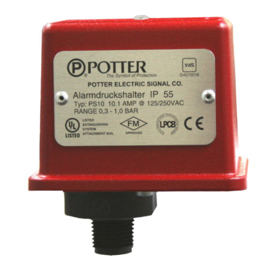
Models:
PS10-1 VDS
PS10-2 VDS
Service Use:
Automatic Sprinkler
One or two family dwelling
Residential Occupancy up to four stories
National Fire Alarm Code
Tamper: Cover incorporates tamper resistant fastener that requires a special key
for removal. One key is supplied with each device. For optional cover tamper
switch kit, order Stock No. 0090200. See bulletin #5401200 PSCTSK.
Installation
The Potter PS10 Series Pressure Actuated Switches are designed for the
detection of a waterflow condition in automatic fire sprinkler systems of
particular designs such as wet pipe systems with alarm check valves, dry
pipe, preaction, or deluge valves. The PS10 is also suitable to provide a
low pressure supervisory signal; adjustable between 0,27 and 1,03 BAR (4
and 15PSI).
1. Apply Teflon tape to the threaded male connection on the device.
(Do not use pipe dope)
2. Device should be mounted in the upright position (threaded connection down).
3. Tighten the device using a wrench on the flats on the device.
Wiring Instructions
1. Remove the tamper resistant screw with the special key provided.
2. Carefully place a screwdriver on the edge of the knockout and sharply
apply a force sufficient to dislodge the knockout plug. See Fig 9
3. Run wires through an approved conduit connector and affix the connector
to the device.
4. Connect the wires to the appropriate terminal connections for the service
intended. See Figures 2,4,5, and 6. See Fig 7 for two switch, one conduit
wiring.
Testing: The operation of the pressure alarm switch should be tested upon
completion of installation and periodically thereafter in accordance with the
applicable NFPA codes and standards and/or the authority having jurisdiction
(manufacturer recommends quarterly or more frequently).
Wet System
METHOD 1: When using PS10 and control unit with retard - connect PS10
into alarm port piping on the input side of retard chamber and electrically
connect PS10 to control unit that provides a retard to compensate for surges.
Potter Electric Signal Company • St. Louis, MO • Customer Service: 866-572-3005 • Tech Support: 866-956-0988 • Canada 888-882-1833 • www.pottersignal.com
PRINTED IN USA
UL, cUL, and CSFM Listed, FM and LPC Approved, NYMEA
Accepted, CE Marked
Dimensions: (9,6cm) 3.78" W x (8,1cm) 3.20" D x (10,7cm) 4.22" H
Conduit Entrance: Two knockouts provided for 1/2" conduit. Individual
Enclosure: Cover - Die-cast with textured red powdercoat finish, single
Pressure Connection: Nylon 1/2" NPT Male
Factory Adjustment: 0,27 - 0,55 BAR (4 - 8 PSI)
Differential: 0,13 BAR (2 PSI) typical
Maximum System Pressure: 17,2 BAR (250 PSI)
Switch Contacts: SPDT (Form C)
NFPA-13
Environmental Specifications:
NFPA-13D
NEMA 4/IP66 Rated Enclosure - indoor or outdoor when used
NFPA-13R
with NEMA 4 conduit fittings.
NFPA-72
Temperature range: -40°C to 60°C (-40° - 140°F)
Insure that no unsupervised shut-off valves are present between the alarm
check valve and PS10.
METHOD 2: When using the PS10 for local bell application or with a control
that does not provide a retard feature - the PS10 must be installed on the alarm
outlet side of the retard chamber of the sprinkler system.
TESTING: Accomplished by opening the inspector's end-of-line test valve.
Allow time to compensate for system or control retard.
NOTE: Method 2 is not applicable for remote station service use, if there
is an unsupervised shut-off valve between the alarm check valve and the
PS10.
Wet System With Excess Pressure
Connect PS10A into alarm port piping extending from alarm check valve.
Retard provisions are not required. Insure that no unsupervised shut-off
valves are present between the alarm check valve and the PS10.
TESTING: Accomplished by opening the water by-pass test valve or the
inspector's end-of-line test valve. When using end-of-line test, allow time
for excess pressure to bleed off.
Dry System
Connect PS10 into alarm port piping that extends from the intermediate
chamber of the alarm check valve. Install on the outlet side of the in-line
check valve of the alarm port piping. Insure that no unsupervised shut-off
valves are present between the alarm check valve and the PS10.
TESTING: Accomplished by opening the water by-pass test valve.
Note: The above tests may also activate any other circuit closer or water
motor gongs that are present on the system.
MFG. #5401162 - REV C-1
12/10
MODEL PS10 (VDS)
PRESSURE SWITCH
switch compartments and ground screws suitable for
dissimilar voltages.
cover screw and rain lip.
Base - Die-cast
10.1 Amps at 125/250VAC, 2.0 Amps at 30VDC
One SPDT in PS10-1, Two SPDT in PS10-2
PAGE 1 OF 8
Advertisement
Table of Contents

Related Manuals for Potter PS10 Series


Summary of Contents for Potter PS10 Series
- Page 1 PS10 to control unit that provides a retard to compensate for surges. Potter Electric Signal Company • St. Louis, MO • Customer Service: 866-572-3005 • Tech Support: 866-956-0988 • Canada 888-882-1833 • www.pottersignal.com PRINTED IN USA MFG.
- Page 2 Closing of any shutoff valves between the alarm check valve and the PS10 will render the PS10 inoperative. To comply with NFPA-72 any such valve shall be electrically supervised with a supervisory switch such as Potter Model RBVS. WET SYSTEM WITHOUT...
- Page 3 MODEL PS10 (VDS) PRESSURE SWITCH Local Bell For Waterflow Connection One Conduit Wiring Fig. 6 Break out thin section of divider to provide path for wires when wiring both switches from one conduit entrance. NEGATIVE DC Fig. 7 OR NEUTRAL AC BELL LINE LOAD...
- Page 4 0,27 - 0,55 BAR (4 - 8 PSI). Pressure type waterflow switches; shall be a Model PS10 as manufactured by Potter Electric Signal Company, St. Louis MO., Pressure switch shall have one or two form C contacts, switch and shall be installed on the fire sprinkler system as shown and or contact rating 10.1 Amps at 125/250 VAC, 2.0 Amps at 30 VDC.
- Page 5 Wasserturbinen mit Gongs auswirken, die im System vorhanden sind. wird der PS10 auf der Eingangsseite der Verzögerungskammer in die Alarmverrohrung Potter Electric Signal Company • St. Louis, MO • Customer Service: 866-572-3005 • Tech Support: 866-956-0988 • Canada 888-882-1833 • www.pottersignal.com MFG. #5401162 - REV C-1...
- Page 6 VORSICHT: Durch das Schließen eines beliebigen Absperrventils zwischen dem Alarmventil und dem PS10 wird der PS10 außer Betrieb gesetzt. Gemäß NFPA-72 sollte jedes derartige Ventil mithilfe eines Überwachungsschalters wie etwa dem Modell RBVS von Potter elektronisch überwacht werden. NASSANLAGE OHNE...
- Page 7 MODELL PS10 (VDS) DRUCKSCHALTER Lokale Glocke Für Integration Verkabelung Mit Einer Rohrleitung In Wasserdurchfluss Dünnen Bereich der Trennwand herausbrechen, um bei Verkabelung beider Schalter Abb. 6 über eine Rohrleitungsöffnung die Kabel entsprechend verlegen zu können. NEGATIVE DC Abb. 7 ODER NEUTRALE AC GLOCKE LEITUNG LAST...
- Page 8 Bei diesem Druckschalter für den Wasserdurchfluss handelt es Schalterkontakte sind auf 10,1 A bei 125/250 VAC und auf 2,0 A bei sich um das von Potter Electric Signal Company, St. Louis, MO., 30 VDC ausgelegt. gefertigte Modell PS10, das gemäß den Abbildungen und/oder Die Druckschalter für den Wasserdurchfluss verfügen über zwei...
- Page 9 Mouser Electronics Authorized Distributor Click to View Pricing, Inventory, Delivery & Lifecycle Information: AMSECO PS-10-EX...
Need help?
Do you have a question about the PS10 Series and is the answer not in the manual?
Questions and answers