
Related Manuals for Evolution R255 PTS


Summary of Contents for Evolution R255 PTS
- Page 1 Original Instructions Written originally in UK English Date Published: 01/02/2020...
- Page 2 Evolution Power Tools website. We operate several helplines throughout our worldwide organization, but technical help is also available from your supplier.
-
Page 3: Machine Specifications
www.evolutionpowertools.com MACHINE SPECIFICATIONS MACHINE METRIC IMPERIAL Motor UK/EU: 220-240V ~ 50Hz (S1) S1 1500W S6 40% 1800W Minimum Table Surface Area: 720mm x 640mm 28-3/8 x 25-3/16 “ Maximum Table Surface Area: 1020mm x 640mm 40-1/8 x 25-3/16” Dimensions With Leg Assembly (H x W x L): 1030 x 750 x 940mm 40-1/2 x 29-1/2 x 37”... - Page 4 WARNING: Do not operate this machine if vibration in the workplace is given in: warning and/or instruction labels are missing BS EN ISO 5349-1:2001 and or damaged. Contact Evolution Power Tools BS EN ISO 5349-2:2002 for replacement labels. • Many factors can influence the actual Note: All or some of the symbols on the vibration level during operation e.g.
-
Page 5: Power Tool
Description WARNING: This product is a table saw and Volts has been designed to be used with special Amperes Evolution blades. Only use accessories designed for use in this machine and/or Hertz those recommended specifically by Evolution Power Tools Ltd. - Page 6 www.evolutionpowertools.com SAFETY PRECAUTIONS of flammable liquids, gasses or dust. Power tools create sparks which may ignite ELECTRICAL SAFETY the dust or fumes. (1.14) c) Keep children and bystanders away while This machine is fitted with the correct moulded plug and mains lead for the designated market. operating power tool.
- Page 7 www.evolutionpowertools.com hard hat or hearing protection used for risk of starting the power tool accidentally. appropriate conditions will reduce d) Store idle power tools out of the reach of personal injuries. children and do not allow persons unfamiliar c) Prevent unintentional starting. Ensure the with the power tool or these Instructions switch is in the off-position before connecting to operate the power tool.
- Page 8 www.evolutionpowertools.com the workpiece before the switch is damage. The young and unborn children are turned on. Inadvertent contact of these particularly vulnerable. You are advised to consider the risks associated with the materials items with the saw blade could cause a you are working with and to reduce the risk hazardous condition.
- Page 9 www.evolutionpowertools.com workpiece feeding force between the may wedge under the rip fence and create fence and the saw blade. Use a push a kickback. stick when the distance between the fence and the saw blade is less than 3) Kickback causes and related warnings 150mm, and use a push block when this distance is less than 50mm.
- Page 10 www.evolutionpowertools.com enough room to easily handle the may cut objects that can cause kickback. g) Support large panels to minimise size of your workpiece. Cramped, dark the risk of saw blade pinching and areas, and uneven slippery floors invite kickback. Large panels tend to sag under accidents.
- Page 11 The manufacturing date code is the first part of this machine the following accessories are also the serial number, found on the motor housing available from the Evolution online shop at of the machine. Evolution serial numbers www.evolutionpowertools.com begin with the abbreviation of the machine followed by a letter.
-
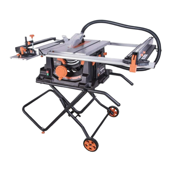
Page 12: Machine Overview
www.evolutionpowertools.com MACHINE OVERVIEW A. BLADE GUARD I. LATCHING PIN B. BLADE (NOT VISIBLE) J. BLADE HEIGHT & BEVEL C. RIVING KNIFE ADJUSTMENT WHEEL D. RIP FENCE K. BEVEL LOCKING LEVER E. RIP FENCE LOCKING HANDLE L. ON/OFF SWITCH F. PUSH STICK STORAGE M. - Page 13 www.evolutionpowertools.com WHAT’S IN THE BOX LATCHING PIN LOCKING LATCH 1. STAND COMPONENT 8. BLADE GUARD 2. STAND COMPONENT 9. MITRE GAUGE 3. STAND COMPONENT 10. ANTI VIBRATION DEVICE 4. STAND COMPONENT 11. PUSH STICK 5. STAND COMPONENT 12. RIP FENCE 6.
-
Page 14: Did You Know
www.evolutionpowertools.com DID YOU KNOW? We’ve made a handy assembly video that shows simple step by step instructions to help you assemble your machine. Scan here or visit www.evolutionpowertools.com/uk/build/tablesaws/assembly ASSEMBLY To assemble this saw you will need: Cross head screwdriver, 8mm & 10mm spanner or socket wrench, 13mm Socket wrench, 5mm allen key and a rubber mallet. - Page 15 www.evolutionpowertools.com STEP 1 STEP 2 Fig. 1 Fig. 2 Fig. 3 STEP 3 Fig. 4 Fig. 5 Fig. 6 STEP 4 STEP 5 Fig. 8 Fig. 9 Fig. 7 STEP 6 STEP 7 Fig. 10 Fig. 11 Fig. 12...
- Page 16 www.evolutionpowertools.com Some further minor assembly is required to commission this machine. WARNING: This machine is heavy. Enlist competent help when removing this machine from its packaging. DEPLOYING THE LEGS The legs are stored underneath the machines main body. • Release the retaining latch (Fig 13). •...
-
Page 17: The Rip Fence
www.evolutionpowertools.com THE BLADE GUARD The Blade Guard labelled 8 must be attached to the machines riving knife. Note: The machine should never be used without this guard in its service position. WARNING: The machine must be disconnected from the mains supply when installing the blade guard. To attach the Blade Guard Fig. -
Page 18: Checking/Adjusting The Rip Fence
www.evolutionpowertools.com CHECKING/ADJUSTING THE RIP FENCE When the Rip Fence has been attached to the machine, the Rip Fence should be checked to ensure that it lies parallel to the blade. • Raise the blade to its full height. • Rest a straight-edge or similar against the blade. •... -
Page 19: Raising/Lowering The Blade
www.evolutionpowertools.com OPERATIONS THE CONTROLS ON/OFF SAFETY SWITCH WARNING: Before operating the ON/OFF switch make sure that the blade guard is correctly installed and operating properly. • Push the ‘ON’ button to start the machine. (Fig. 25) • Push the ‘OFF’ button to stop the machine. Fig. - Page 20 www.evolutionpowertools.com THE RIP FENCE This machine is fitted with a two piece Rip Fence. We recommend that the Rip Fence is normally used in conjunction with its adjustable Face Plate. The Rip Fence should normally be positioned to the RH side of the blade.
- Page 21 www.evolutionpowertools.com Note: The face plate of the mitre gauge should be adjusted so that it passes close to, but does not touch the blade guard as it slides past during a cut. Adjust by loosening the finger nuts and sliding the faceplate to the required position.
-
Page 22: Sliding Carriage
www.evolutionpowertools.com SLIDING CARRIAGE This machine is fitted with a Sliding Carriage (Fig. 34) to the LH side of the blade. This facility can be particularly useful when cross-cutting small section material such as metal box- section or extrusions etc. Such material can be clamped to the Sliding Carriage by using the secured Mitre Gauge and its Hold Down Clamp. -
Page 23: Mitre Crosscutting
www.evolutionpowertools.com CROSSCUTTING Set the Mitre Gauge to 0˚ and tighten the vertical locking screw. If employing the Sliding Carriage position the Mitre Gauge in the LH ‘T’ slot and lock it in place by screwing the locking screw into the locating hole. Note: The Mitre Gauge can be used on the RH side of the blade if required. -
Page 24: Repetitive Cross Cutting
www.evolutionpowertools.com REPETITIVE CROSS CUTTING Repetitive Cross Cutting is the process of cutting a number of pieces to the same length without having to mark out each piece separately. Note: We recommend that repetitive cross-cutting is carried out with the Mitre Gauge positioned on the LH side of the machine, with the Rip Fence on the RH side of the machine (Fig. -
Page 25: Bevel Ripping
Note: If the push stick becomes damaged it should be replaced. If the operator makes their own push stick, we recommend that it follows the same pattern as that supplied. (Replacement push sticks are available from Evolution Power Tools.) MAINTENANCE WARNING: Ensure that the machine is disconnected from the mains supply before any maintenance tasks or adjustments are attempted. -
Page 26: Tool Storage
Inspect the riving knife at regular intervals and replace it if it is worn or damaged. Note: Use only a genuine Evolution Riving Knife, as this is a dedicated component for this machine. Non genuine parts could Fig. 49 be dangerous. -
Page 27: Ec Declaration Of Conformity
In accordance with EN ISO 17050-1:2004 The manufacturer of the product covered by this Declaration is: UK: Evolution Power Tools Ltd. Venture One, Longacre Close, Holbrook Industrial Estate, Sheffield, S20 3FR. FR: Evolution Power Tools SAS. 61 Avenue Lafontaine, 33560, Carbon-Blanc, Bordeaux, France. - Page 28 Total Tools (Importing) Pty Ltd Evolution Power Tools SAS 20 Thackray Road 61 Avenue Lafontaine Port Melbourne 33560, Carbon-Blanc Vic 3207 Bordeaux T: 03 9261 1900 T: +33 (0)5 57 30 61 89 Evolution Power Tools Ltd Evolution Power Tools LLC...
Need help?
Do you have a question about the R255 PTS and is the answer not in the manual?
Questions and answers