
Related Manuals for Evolution R255 MTS


Summary of Contents for Evolution R255 MTS
- Page 1 Original Instructions Original written in UK English Date Published: 06 / 06 / 2019...
- Page 2 You can also scan the QR code found on the A4 leaflet with a smart phone. This will enable you to validate your machine’s guarantee period via Evolution’s website by entering your details and thus ensure prompt service, if ever needed. We sincerely thank you for selecting...
-
Page 3: Machine Specifications
www.evolutionpowertools.com MACHINE SPECIFICATIONS MACHINE METRIC IMPERIAL Motor (UK/EU) 220-240v ~ 50Hz 1300W (S1) 5.65A 1500W (S6 40%) Maximum Table Surface Area 583 x 901mm 22-15/16” x 35-1/2” Dimensions With Leg Assembly 825 x 901 x 583mm 32-1/2” x 35-1/2” x 22-15/16” (Height x Width x Length) Dimensions Without Leg Assembly 300 x 901 x 583mm... - Page 4 WARNING: Do not operate this machine if • The measurement and assessment of warning and/or instruction labels are missing human exposure to hand-transmitted or damaged. Contact Evolution Power Tools vibration in the workplace is given in: for replacement labels. BS EN ISO 5349-1:2001 and...
-
Page 5: Intended Use Of This Power Tool
Symbol Description WARNING: This product is a table saw and has Volts been designed to be used with special Evolution blades. Only use accessories designed for use Amperes in this machine and/or those recommended specifically by Evolution Power Tools Ltd Hertz which conforms to EN 847-1. - Page 6 www.evolutionpowertools.com SAFETY PRECAUTIONS or fumes. c) Keep children and bystanders away while ELECTRICAL SAFETY operating power tool. Distractions can cause (1.14) you to lose control. This machine is fitted with the correct moulded 2) General Power Tool Safety Warnings plug and mains lead for the designated (2.3) [Electrical Safety] market.
- Page 7 www.evolutionpowertools.com the switch on invites accidents. cutting edges are less likely to bind and are d) Remove any adjusting key or wrench easier to control. before turning the power tool on. g) Use the power tool, accessories and A wrench or key left attached to a rotating part tool bits etc.
- Page 8 www.evolutionpowertools.com eye damage. Before beginning power tool wider than the thickness of the riving knife. operation, always wear safety goggles or safety 2) Cutting procedures warnings glasses with side shield or a full face shield where necessary. DANGER: Never place your fingers or ADDITIONAL SAFETY INSTRUCTIONS hands in the vicinity or in line with the - TABLE SAWS...
- Page 9 www.evolutionpowertools.com e) Use a featherboard to guide the causing loss of control, saw blade binding workpiece against the table and fence and kickback. j) Feed workpiece at an even pace. Do not when making non-through cuts such as bend or twist the workpiece. If jamming rabbeting, dadoing or resawing cuts.
- Page 10 In addition to the standard items supplied Caution: This packaging contains sharp with this machine the following accessories objects. Take care when unpacking. are also available from the Evolution online Remove the machine, together with the shop at www.evolutionpowertools.com accessories supplied from the packaging. Check or from your local retailer.
-
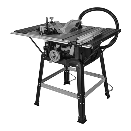
Page 11: Machine Overview
www.evolutionpowertools.com MACHINE OVERVIEW 1. ON/OFF SWITCH 9. PUSH STICK 2. RIVING KNIFE 10. RIP FENCE 3. BLADE GUARD 11. REAR CANTILEVER BRACES 4. BLADE 12. ANTI-BOUNCE DEVICE 5. BEVEL LOCKING KNOB 13. SLIDING MITRE FENCE 6. RISE AND FALL/BEVEL ADJUSTMENT 14. -
Page 12: What's In The Box
www.evolutionpowertools.com WHAT’S IN THE BOX A. BLACK CORNER LEGS (STAMPED A) x 4 K. MITRE GAUGE B. CROSS-BRACES (STAMPED B) L. FENCE RAIL 2 pieces C. CROSS-BRACES (STAMPED C) M. FENCE RAIL JOINING TONGUE D. REAR CANTILEVER BRACES N. HEX HEADED SCREW x 28 E. - Page 13 www.evolutionpowertools.com ASSEMBLY Note: This process can be considerably aided by studying the images of an assembled machine as found on the machine overview page. THE STAND Four corner legs (stamped A) and four cross-braces (B+C) comprise the main stand components. Fig.
- Page 14 www.evolutionpowertools.com • Attach the side cross-braces (C) to the corner legs (Fig. 5) in the same manner that the front and rear cross-braces were attached. • Push fit the rubber feet (E) onto the bottom of each leg. Note: The machine can now be lifted from the work-surface/workbench.
-
Page 15: The Fence Rail
www.evolutionpowertools.com • Insert the machine screw through the end of the support strut and refit the machine screw to the machines main body. (Fig. 9) Use a straight edge or similar placed across the table and the extension panel to check the alignment. The extension panels should be exactly level with and flush to the main table of the machine. -
Page 16: Checking/Adjusting The Rip Fence
www.evolutionpowertools.com • Loosen slightly the seven coach bolts (P) which hold the fence rail to the machine. • Gently move the fence rail to the right or left until the ‘0’ position on the scale coincides with the datum line in the magnifier. -
Page 17: Top Blade Guard
www.evolutionpowertools.com thin walled metal tube etc). At other times safely store the device off the machine. The pillar of the anti-bounce device fits into the socket in the mitre gauge base, and is held in place by a thumb screw. (Fig 17) TOP BLADE GUARD The top blade guard (H) (Fig. -
Page 18: Operation
(Fig. 22) Note: The ‘free’ port of the 2 way connector can be used to attach a workshop dust extraction machine to this Evolution machine. If such a machine is connected to this Table Saw follow the Instructions provided by the supplier/manufacturer of the dust extraction equipment. -
Page 19: Tilting The Blade
www.evolutionpowertools.com To raise or lower the blade: • Ensure that the hand-wheel is in the ‘normal’ (outer) position. • Turn the hand-wheel clockwise to raise the blade. • Turn counter clockwise to lower the blade. Note: When the machine is not in use we recommend that the blade is fully lowered into the machine and that the top guard is lying flush on the saw table. -
Page 20: Mitre Gauge
www.evolutionpowertools.com Note: We recommend that normally the rip fence faceplate be adjusted so that the rear of the faceplate guide is ‘in line’ with the rear of the blade where it emerges from the table. (Fig. 28B) Note: If the rip fence is used on the LH (left hand) side of the blade, the aluminium faceplate will have to be repositioned to the RH (right hand) side of the aluminium carrier. -
Page 21: Anti-Bounce Device
www.evolutionpowertools.com Turn the vertical handle counter-clockwise to unlock the mitre gauge, and adjust to the required angle. Turn the handle clockwise to lock the mitre gauge at the chosen angle. Note: The extruded aluminium faceplate of the mitre gauge should be adjusted so that it passes close to, but does not touch the blade or blade guard. -
Page 22: Mitre Cross-Cutting
www.evolutionpowertools.com WARNING: This machine is not suitable for cutting rebates or stopped grooves. A workshop dust extraction machine can be connected to the extraction port found at the rear of the machine if required. CROSS-CUTTING Set the mitre gauge to 0˚ and tighten using the vertical handle. Position in the desired ‘T’... -
Page 23: Rip Cutting
www.evolutionpowertools.com To set the rip fence for repetitive cross-cutting: • Set the rip fence at the required distance from the saw blade. • Adjust and align the back of the rip fence faceplate with the front of the saw blade. (Fig. 39) This setting will afford clearance for the material as it passes through the saw blade. -
Page 24: Bevel Ripping
• Replace the table access plate and its fixing screw. Ensure that the fixing screw is correctly seated. • Replace the top blade guard. REPLACING DAMAGED CABLE If cable is damaged in any way, ensure it is repaired by Evolution or one of its approved agents. Fig. 45... -
Page 25: Adjusting The Riving Knife
Note: Use only a genuine Evolution riving knife, as this is a dedicated component for this machine. Non genuine parts could be dangerous. -
Page 26: Ec Declaration Of Conformity
In accordance with EN ISO 17050-1:2004 The manufacturer of the product covered by this Declaration is: UK: Evolution Power Tools Ltd. Venture One, Longacre Close, Holbrook Industrial Estate, Sheffield, S20 3FR. FR: Evolution Power Tools SAS. 61 Avenue Lafontaine, 33560, Carbon-Blanc, Bordeaux, France. - Page 27 www.evolutionpowertools.com Notes...
- Page 28 Total Tools (Importing) Pty Ltd Evolution Power Tools SAS 20 Thackray Road 61 Avenue Lafontaine Port Melbourne 33560, Carbon-Blanc Vic 3207 Bordeaux T: 03 9261 1900 T: +33 (0)5 57 30 61 89 Evolution Power Tools Ltd Evolution Power Tools LLC...
Need help?
Do you have a question about the R255 MTS and is the answer not in the manual?
Questions and answers