Advertisement
Table of Contents
- 1 Table of Contents
- 2 Service Manual
- 3 Important Notice
- 4 To Service Personnel
- 5 Front Panel
- 6 Remote Control Panel
- 7 Rear Panels
- 8 Specifications
- 9 Internal View
- 10 Disassembly Procedures
- 11 Updating Firmware
- 12 Self Diagnosis Function (Diag)
- 13 Amp Adjustment
- 14 Display Data
- 15 IC Data
- 16 Remote Control
- Download this manual
See also:
Owner's Manual
This manual has been provided for the use of authorized YAMAHA Retailers and their service personnel.
It has been assumed that basic service procedures inherent to the industry, and more specifically YAMAHA Products, are already
known and understood by the users, and have therefore not been restated.
WARNING:
IMPORTANT:
The data provided is believed to be accurate and applicable to the unit(s) indicated on the cover. The research, engineering, and
service departments of YAMAHA are continually striving to improve YAMAHA products. Modifications are, therefore, inevitable
and specifications are subject to change without notice or obligation to retrofit. Should any discrepancy appear to exist, please
contact the distributor's Service Division.
WARNING:
IMPORTANT:
I CONTENTS
TO SERVICE PERSONNEL .......................................... 2
FRONT PANEL .............................................................. 3
REMOTE CONTROL PANEL ........................................ 3
REAR PANELS .............................................................. 4
SPECIFICATIONS ...................................................... 5~7
INTERNAL VIEW ........................................................... 8
DISASSEMBLY PROCEDURES ............................. 9~12
UPDATING FIRMWARE .............................................. 13
SELF DIAGNOSIS FUNCTION (DIAG) ................. 14~32
AMP ADJUSTMENT .................................................... 33
1 0 0 9 4 2
HTR-5890
Failure to follow appropriate service and safety procedures when servicing this product may result in personal
injury, destruction of expensive components, and failure of the product to perform as specified. For these reasons,
we advise all YAMAHA product owners that any service required should be performed by an authorized
YAMAHA Retailer or the appointed service representative.
The presentation or sale of this manual to any individual or firm does not constitute authorization, certification or
recognition of any applicable technical capabilities, or establish a principle-agent relationship of any form.
Static discharges can destroy expensive components. Discharge any static electricity your body may have
accumulated by grounding yourself to the ground buss in the unit (heavy gauge black wires connect to this buss).
Turn the unit OFF during disassembly and part replacement. Recheck all work before you apply power to the unit.
AV RECEIVER
SERVICE MANUAL
IMPORTANT NOTICE
DISPLAY DATA ........................................................... 34
IC DATA ................................................................. 35~41
BLOCK DIAGRAM ................................................. 42~43
PRINTED CIRCUIT BOARD .................................. 44~60
PIN CONNECTION DIAGRAM .............................. 61~62
SCHEMATIC DIAGRAM ........................................ 63~71
PARTS LIST ........................................................... 73~90
REMOTE CONTROL .................................................... 91
Parts List for Carbon Resistors ................................ 92
P.O.Box 1, Hamamatsu, Japan
'05.03
Advertisement
Table of Contents

Related Manuals for Yamaha HTR-5890


Summary of Contents for Yamaha HTR-5890
-
Page 1: Table Of Contents
This manual has been provided for the use of authorized YAMAHA Retailers and their service personnel. It has been assumed that basic service procedures inherent to the industry, and more specifically YAMAHA Products, are already known and understood by the users, and have therefore not been restated. -
Page 2: To Service Personnel
HTR-5890 I TO SERVICE PERSONNEL AC LEAKAGE WALL EQUIPMENT TESTER OR 1. Critical Components Information OUTLET UNDER TEST EQUIVALENT Components having special characteristics are marked s and must be replaced with parts having specifications equal to those originally installed. 2. Leakage Current Measurement (For 120V Models Only) -
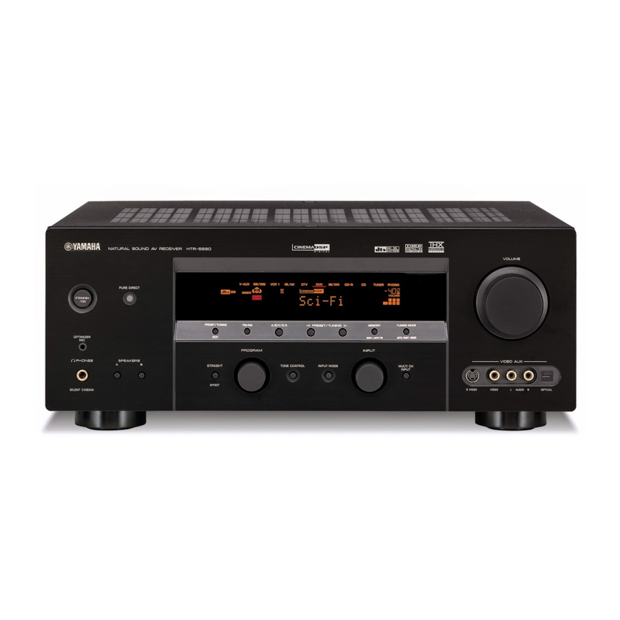
Page 3: Front Panel
HTR-5890 I FRONT PANEL I REMOTE CONTROL PANEL... -
Page 4: Rear Panels
HTR-5890 I REAR PANELS U, C models A model... -
Page 5: Specifications
................1.5 Vp-p or more PHONO (MM) ..........3.5 mV / 47 k-ohms Video Signal to Noise Ratio "SILENT CINEMA" is a trademark of YAMAHA CORPORATION. CD, etc............200 mV / 47 k-ohms ................. 60 dB or more MULTI CH INPUT... - Page 6 HTR-5890...
- Page 7 HTR-5890...
-
Page 8: Internal View
HTR-5890 I INTERNAL VIEW 3 4 5 6 7 8 1 POWER (5) P.C.B. 2 MAIN (1) P.C.B. 3 POWER (7) P.C.B. 4 MAIN (5) P.C.B. 5 POWER (6) P.C.B. 6 MAIN (3) P.C.B. 7 VIDEO (4) P.C.B. 8 TUNER 9 CONVERSION P.C.B. -
Page 9: Disassembly Procedures
HTR-5890 I DISASSEMBLY PROCEDURES (Remove parts in the order as numbered.) Disconnect the power cable from the AC outlet. 1. Removal of Top Cover 2. Removal of Front Panel Unit a. Remove 2 screws (1), 4 screws (2) and 5 screws (3). - Page 10 HTR-5890 3. Removal of DSP P.C.B. a. Remove 2 screws (5) and then remove the Support. CB555 CB558 CB554 (Fig. 4) b. Remove 5 screws (6) and then remove the Bracket. (Fig. 4) c. Remove 1 screw (7). (Fig. 4) CB504 d.
- Page 11 HTR-5890 5. Removal of VIDEO (1), (3), (5) ~ (8), FUNCTION, CONVERSION P.C.B.s and Tuner a. Remove 26 screws (0). (Fig. 5) b. Remove VIDEO (1), (3), (5) ~ (8), FUNCTION, CONVERSION P.C.B.s and Tuner. When checking the P.C.B.: • Put the Rubber Sheet and a Cloth over the equipment.
- Page 12 HTR-5890 6. Removal of Fan When checking the Amp Unit: a. Remove 4 push rivets (A) and then remove the Cover. • Put the Amp Unit together with the heat sink upright (Fig. 8) on the art base and check them. (Fig. 9) b.
-
Page 13: Updating Firmware
HTR-5890 I UPDATING FIRMWARE After replacing the IC512 on the FUNCTION P.C.B. with 2. After executing the firmware loading program, select the service part (X4678A00), update the firmware the program type and port settings as follows: according to the following procedure. -
Page 14: Self Diagnosis Function (Diag)
HTR-5890 I SELF DIAGNOSIS FUNCTION (DIAG) There are 18 DIAG menu items, each of which has sub-menu items. Listed in the table below are menu items and sub-menu items. No DIAG menu sub-menu DA601-YSS930 1. YSS 0dB 2. YSS FULL BIT BYPASS 1. - Page 15 HTR-5890 No DIAG menu sub-menu 12 AD DATA CHECK 1. DC/PS (protection) /FAN TEST 2. THM/FAN OUT 3. REC-OUT 4. IMP SW/POWER LIMIT 5. K0/K1 (panel key) 6. FAN DRIVE TEST: HIGH 7. FAN DRIVE TEST: MID 8. FAN DRIVE TEST: LOW 13 V CONV STATUS 1.
- Page 16 HTR-5890 • Starting DIAG • Display provided when DIAG started Press the “STANDBY/ON” key while simultaneously When the monitor is connected, DIAGNOSTIC MENU pressing those two keys of the main unit as indicated in the appears on its screen as shown in the figure. (It remains figure below.
- Page 17 HTR-5890 When there is a history of protection • History of protection function function due to abnormal voltage in When the protection function has worked, its history is Version (1 alphabet) the power supply section stored in memory with a backup. Even if no abnormality...
- Page 18 HTR-5890 • Functions in DIAG mode • Initial settings used to start DIAG In addition to the DIAG menu items, functions as listed The following initial settings are used when starting DIAG. below are available. When DIAG is canceled, these settings are restored to •...
- Page 19 HTR-5890 YSS FULL BIT • The signal is output in digital full bit without including the head margin. • The SWFR signal is output but not in digital full bit. Reference data INPUT: DVD ANALOG SUBWOOFER: 50Hz, Others: 1kHz SPEAKER OUTPUT...
- Page 20 HTR-5890 DSP BYPASS Reference data INPUT: DVD ANALOG SUBWOOFER: 50Hz, Others: 1kHz SPEAKER OUTPUT SUBWOOFER Input level Volume FRONT L/R CENTER SURROUND L/R SURROUND BACK OUTPUT - ∞ - ∞ - ∞ - ∞ - ∞ Both ch, -20 dBm +6.5 dB...
- Page 21 HTR-5890 3. RAM THROUGH Using the sub-menu, it is possible to select the full-bit output at 0dB output level. RAM 0dB Reference data INPUT: DVD ANALOG SUBWOOFER: 50Hz, Others: 1kHz SPEAKER OUTPUT SUBWOOFER Input level Volume FRONT L/R CENTER SURROUND L/R SURROUND BACK...
- Page 22 HTR-5890 4. PRO LOGIC / NEO6 PRO LOGIC I Reference data INPUT: DVD ANALOG SUBWOOFER: 50Hz, Others: 1kHz SPEAKER OUTPUT SUBWOOFER Input level Volume FRONT L/R CENTER SURROUND L/R SURROUND BACK OUTPUT - ∞ - ∞ - ∞ - ∞...
- Page 23 HTR-5890 5. SPEAKERS SET The input signal is automatically identified in the order of dts → DOLBY DIGITAL → AAC→ PCM → Analog. There are seven sub-menu items as follows. The signals output from the DSP block are the same as 1.
- Page 24 HTR-5890 6. EXTERNAL INPUT It is possible to select the 6ch/8ch input and 6_/8_ by using the SUB menu. 6CH_INPUT_6OHMS 6CH_INPUT_8OHMS 8CH_INPUT_6OHMS 8CH_INPUT_8OHMS Reference data INPUT: MULTI CH INPUT SUBWOOFER: 50Hz, Others: 1kHz SPEAKER OUTPUT SUBWOOFER Sub-menu Input level Volume...
- Page 25 HTR-5890 8. EFFECT OFF / DISPLAY CHECK This program is used to check the FL display section. The display condition varies as shown below according to the sub-menu operation. The signals are processed using EFFECT OFF (The L/R signal is output using ANALOG MAIN BYPASS.)
- Page 26 HTR-5890 9. MANUAL TEST The noise generator with a built-in DSP outputs the test noise through the channels specified by the sub-menu. The noise frequency for LFE is 35 to 250 Hz. Other than that, the center frequency is 800Hz.
- Page 27 HTR-5890 11. FACTORY PRESET This menu is used to reserve and inhibit initialization of the back-up RAM. The signals are processed using EFFECT OFF. (The L/R signal is output using ANALOG MAIN BYPASS.) PRESET INHIBIT (Initialization inhibited) RAM initialization is not executed. Select this sub-menu to protect the values set by the user.
- Page 28 HTR-5890 THM/FAN OUT (temperature detection/fan drive level) THM: Temperature detected value Normal value: 10 to 139 (Reference voltage: 5V=500% ) Fan: Current fan drive level on the left and the past fan drive history on the right. Display fan drive level HIGH REC-OUT (Select position) Not applied to this model.
- Page 29 HTR-5890 FAN DRIVE TEST HIGH FAN DRIVE TEST FAN DRIVE TEST 13. V CONV STATUS 14. IF STATUS (Input function status) The data received from the video conversion IC Using the sub-menu, the status data is displayed one (TA1270) is displayed.
- Page 30 HTR-5890 <2nd byte> Fs information of reproduction signal Display Fs (kHz) Analog 44.1 88.2 Unknown NRM Unknown DBL Unknown QUAD Not defined <3rd byte> A u d i o c o d e m o d e i n f o r m a t i o n o f...
- Page 31 Data bus shorted or open. MODEL SETTING RSCS /RAS or /CAS shorted, or open. ADDR Address bus shorted or open. V1500 (HTR-5890) model only. SECOND DECODER (DA601) BUS CHECK TUNER DESTINATION J, UC, AG or RL can be selected. Display Description...
- Page 32 “PORT:0 0 0 0 0 0 0 0” bit 7 6 5 4 3 2 1 0 Type 0 Type 1 Model type Model type 0 (*1) HTR-5890 (V1500) Model type 1 (*1) Tuner mode 0 (*2) Tuner mode 1 (*2) Tuner with (1) / without (0)
-
Page 33: Amp Adjustment
HTR-5890 I AMP ADJUSTMENT Confirmation of Idling Current of Amp Unit • Right after power is turned on, confirm that the voltage Attention across the terminals of R319 (FRONT Lch), R320 If the idle current exceeds 10.0mV after an amplifier MAIN (2) P. -
Page 34: Display Data
HTR-5890 I DISPLAY DATA G ANODE CONNECTION G V851 : 17-BT-23GNK (WD507500) 14G~2G PATTERN AREA G PIN CONNECTION Pin No. Connection Pin No. Connection Note : 1) F1, F2 ..Filament 2) NP ..No pin 3) NC ..No connection 4) NX .. -
Page 35: Ic Data
HTR-5890 IC509: LC89057W-VF4-E (DSP P.C.B) I IC DATA Digital Audio Interface Transceiver IC509: LC89057W-VF4-E (DSP P.C.B) Name Function Digital Audio Interface Transceiver RXOUT Input bi-phase selection data output pin TTL-compatible digital data input pin Coaxial-compatible digital data input pin with built-in amplifier... - Page 36 HTR-5890 IC512: D601A002PYP180 (DSP P.C.B) IC512: D601A002PYP180 (DSP P.C.B) Decoder Decoder * No service part Digital Signal Processors Name Function avilable. EMIF32 L2 Cache/ L1P Cache Memory SCL0 12C0 clock Direct Mapped 4 Banks McASP1 4K Bytes Total 64K Bytes...
- Page 37 HTR-5890 IC512: D601A002PYP180 (DSP P.C.B) IC512: D601A002PYP180 (DSP P.C.B) Decoder Decoder Name Function Name Function EA17 For external memory, Address 17 CVDD 1.2V power supply EA19 For external memory, Address 19 Ground EA20 For external memory, Address 20 AHCLKX1 General purpose I/O0 port 8...
- Page 38 HTR-5890 IC516, 518: YSS930-SZ (DSP P.C.B.) IC516, 518: YSS930-SZ (DSP P.C.B.) Name Function Digital ground terminal Terminal for connecting crystal oscillator Terminal for connecting crystal oscillator (12.288 ∼ 15.0MHz) VDD2 IOPORT0 I+/O General purpose input/output terminal, SDO0 Lch zero-flag output terminal, input/output terminal for branching program conditions...
- Page 39 HTR-5890 IC516, 518: YSS930-SZ (DSP P.C.B.) Name Function RAMD14 I+/O Data input/output terminal 14 for external memory RAMD15 I+/O Data input/output terminal 15 for external memory CASN Column address strobe output terminal for external DRAM RAMWEN Write enable output terminal for external memory...
-
Page 40: Remote Control
HTR-5890 IC520 : M30805SGP (FUNCTION P.C.B) IC520 : M30805SGP (FUNCTION P.C.B) 16bit µ-COM (Main CPU) 16bit µ-COM (Main CPU) Pin Pin function Function Name Detail of function Backup P96/ANEX1/TxD4/SDA4/SRxD4 TxD4 TXDR 232C TX data / YDC TX data P95/ANEX0/CLK4 CLK4... - Page 41 HTR-5890 IC520 : M30805SGP (FUNCTION P.C.B) IC520 : M30805SGP (FUNCTION P.C.B) 16bit µ-COM (Main CPU) 16bit µ-COM (Main CPU) Pin Pin function Function Name Detail of function Backup Pin Pin function Function Name Detail of function Backup P53/BCLK/ALE/CLKout BCLK BCLK...
Need help?
Do you have a question about the HTR-5890 and is the answer not in the manual?
Questions and answers