
Related Manuals for Yamaha RX-V595RDS


Summary of Contents for Yamaha RX-V595RDS
- Page 1 RX-V595RDS Natural Sound AV Receiver Récepteur audiovisuel OWNER’S MANUAL MODE D’EMPLOI BEDIENUNGSANLEITUNG BRUKSANVISNING MANUALE DI ISTRUZIONI MANUAL DE INSTRUCCIONES GEBRUIKSAANWIJZING...
-
Page 2: Supplied Accessories
SUPPLIED ACCESSORIES ACCESSOIRES FOURNIS MITGELIEFERTE ZUBEHÖRTEILE MEDFÖLJANDE TILLBEHÖR ACCESSORI IN DOTAZIONE ACCESORIOS INCLUIDOS BIJGELEVERDE ACCESSOIRES • Indoor FM Antenna • Antenne FM intérieure • UKW-Innenantenne • Inomhus-FM-antenn • Antenna FM interna • Antena FM interior • FM-binnenantenne • AM Loop Antenna •... -
Page 3: Table Of Contents
Dolby Digital Decoder Dolby Pro Logic Surround Decoder CINEMA DSP: Theater-like Sound Experience by the Combination of Dolby Surround and YAMAHA DSP Technology 6-Channel External Decoder Input for DTS and other future formats SUPPLIED ACCESSORIES ... 2 FEATURES ... 3 CAUTION ... -
Page 4: Caution
Using this unit with a higher voltage than speci- fied is dangerous and may result in fire or other accidents. YAMAHA will not be held responsible for any damage resulting from use of this unit with a voltage other than specified. -
Page 5: Features On Sound Effect
Extensive research into the exact nature of the sonic reflections that create the ambience of a large hall has made it possible for YAMAHA engineers to bring you this same sound in your listening room, so you’ll feel all the sound of a live concert. -
Page 6: Cinema Dsp
SPEAKERS terminals or SUBWOOFER terminal to maximize system performance. YAMAHA DSP technology made it possible to present you with nearly the same sound experience as that of a large movie theater in your listening room by compensating for lack of presence and dynamics in your listening room with its original digital sound fields combined with Dolby Surround sound field. -
Page 7: Front Panel
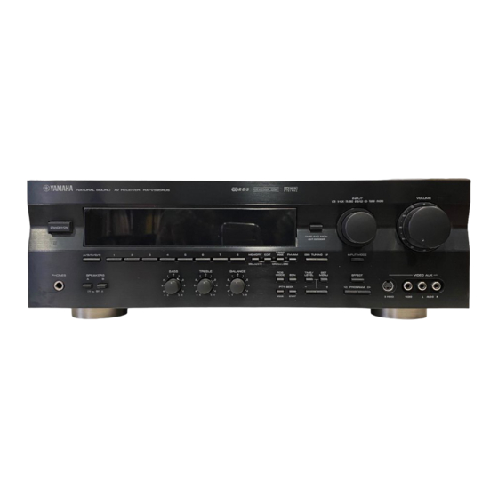
CONTROLS AND THEIR FUNCTIONS FRONT PANEL NATURAL SOUND AV RECEIVER STANDBY/ON A/ B/ C / D/ E PHONES SPEAKERS STANDBY/ON Press this switch to turn the power of this unit on. Press it again to turn this unit into the standby mode. Standby mode In this state, this unit consumes a very small quantity of power to receive infrared-signals from the remote control... - Page 8 INPUT MODE Switches the DVD/LD and TV/DBS input signal mode (AUTO/ ANALOG). VOLUME This control is used to raise or lower the volume level. PHONES jack When you use headphones, connect the headphones to the PHONES jack. You can listen to the sound to be output from the main speakers through headphones.
-
Page 9: Display Panel
DISPLAY PANEL Multi-information display Displays various information, for example station frequency, preset station number and name of selected input source. MEMORY indicator When MEMORY is pressed, this indicator flashes for about five seconds. During this period, the displayed station can be stored to the memory. -
Page 10: Speakers To Be Used
LFE (low frequency effect) sound with high fidelity when playing back a source with the Dolby Digital decoded. You may wish to choose the convenience of a YAMAHA Active Servo Processing Subwoofer System, which has its own built-in power amplifier. 4-Speaker Configuration The center speaker is not used in this configuration. -
Page 11: Speaker Placement
SPEAKER PLACEMENT When you place the speakers, refer to the following diagram: Main speaker Center speaker Subwoofer Main: The position of your present stereo speaker system. Rear: Behind your listening position, facing slightly inward. Nearly 1.8 m (approx. 6 feet) up from the floor. -
Page 12: Connections
(left) to L, R (right) to R, “+” to “+” and “–” to “–”. Also, refer to the owner’s manual for each component to be connected to this unit. * If you have YAMAHA components numbered as !, #, $, etc. on the rear panel, connections can be made easily by making sure to connect the output (or input) terminals of each component to the same-numbered terminals of this unit. - Page 13 SWITCHED AC OUTLET(S) (Europe model) ... 2 SWITCHED OUTLETS (U.K. model) ... 1 SWITCHED OUTLET Use these to connect the power cords from your components to this unit. The power to the SWITCHED outlets is controlled by this unit’s STANDBY/ON or the provided remote control transmitter’s POWER and STANDBY.
- Page 14 CONNECTING TO DIGITAL (COAXIAL AND/OR OPTICAL) TERMINALS If your DVD (LD) player, TV/DBS tuner, etc. are equipped with coaxial or optical digital audio signal output terminals, they can be connected to this unit’s COAXIAL and/or OPTICAL digital signal input terminals. To make a connection between optical digital audio signal terminals, remove the cover from each terminal, and then connect them by using a commercially available optical fiber...
- Page 15 CONNECTING TO S VIDEO TERMINALS If you have a VCR and a monitor equipped with “S” (high- Monitor TV resolution) video terminals, those terminals can be connected to this unit’s S VIDEO terminals. Connect the VCR’s “S” video input and output terminals to this unit’s S VIDEO VCR OUT and IN terminals respectively, and connect the monitor’s “S”...
-
Page 16: Connecting Speakers
If you have a subwoofer with built-in amplifier, including the YAMAHA Active Servo Processing Subwoofer System, connect the SUBWOOFER OUTPUT terminal of this unit to the input terminal of the subwoofer system. - Page 17 How to connect Connect the SPEAKERS terminals to your speakers with wire of the proper gauge, cut as short as possible. If the connections are faulty, no sound will be heard from the speakers. Make sure that the polarity of the speaker wires is correct, that is the + and – markings are observed.
-
Page 18: Impedance Selector Switch
IMPEDANCE SELECTOR SWITCH WARNING Do not change the IMPEDANCE SELECTOR switch setting while the power of this unit is on, otherwise this unit may be damaged. IF THIS UNIT FAILS TO TURN ON WHEN THE STANDBY/ ON SWITCH IS PRESSED, the IMPEDANCE SELECTOR switch may not be fully set to either end. -
Page 19: Antenna Connections
ANTENNA CONNECTIONS Each antenna should be correctly connected to the designated terminals, referring to the following diagram. Both AM and FM indoor antennas are included with this unit. In general, these antennas will probably provide sufficient signal strength. Nevertheless, a properly installed outdoor antenna will give clearer reception than an indoor one. If you experience poor reception quality, an outdoor antenna may result in improvement. -
Page 20: Adjustments Before Using This Unit
ADJUSTMENTS BEFORE USING THIS UNIT SELECTING THE OUTPUT MODES This unit provides you the following five functions to determine the method of distributing output signals to speakers suitable for your audio system. When speaker connections are all completed, select a proper position on each function to make the best use of your speaker system. -
Page 21: Adjusting Method
ADJUSTING METHOD Operations should be made while watching the information on this unit’s display. If you are using the remote control transmitter, set the SELECTOR DIAL to the AMP/TUN or DSP position on the remote control transmitter. Turn the power on. Front panel Press SET MENU once or more to select the title “1. -
Page 22: Speaker Balance Adjustment
SPEAKER BALANCE ADJUSTMENT This procedure lets you adjust the sound output level balance between the main, center and rear speakers using the built-in test tone generator. When this adjustment is performed, the sound output level heard at the listening position will be the same from each speaker. - Page 23 Set BASS, TREBLE and BALANCE to the “0” position. Front panel Press TEST (so that “TEST LEFT” appears on the display). Remote control Turn up the volume. You will hear a test tone (like pink noise) from the left main speaker, then the center speaker, then the right main speaker, then the right rear speaker, and then the left rear speaker, for about two seconds each.
- Page 24 Adjust the sound output levels of the center speaker and the rear speakers so that they become almost as same as that of the main speakers. Remote control a) Press once or more so that “CENTER”, “R SUR.” or “L SUR.” appears on the display. * Select “CENTER”...
-
Page 25: Basic Operations
TO PLAY A SOURCE Notes • Set the SELECTOR DIAL to the AMP/TUN position on the remote control transmitter. • To operate the CD player, DVD/LD player, tape deck, MD recorder, or other components using this remote control transmitter, set the SELECTOR DIAL to the component to be used. -
Page 26: Selecting The Speaker System
For the DVD/LD or TV/DBS source, the current input mode is also shown. * To change the input mode for the DVD/LD or TV/DBS source, press INPUT MODE (or the button that you have pressed to select the input source in step 3 on the remote control transmitter) once or more until the desired input mode (AUTO or ANALOG) is shown on the display. - Page 27 To play a tape or an MD Press TAPE/MD MON / EXT. DECODER so that the “TAPE/MD MON” indicator lights up on the display, then play the tape or MD. Front panel To stop playing the tape or MD, press TAPE/MD MON / EXT. DECODER twice so that the “TAPE/MD MON”...
-
Page 28: To Record A Source To Tape Or Md
TO RECORD A SOURCE TO TAPE OR MD Select the source to be recorded. Front panel Play the source and then turn VOLUME up to confirm the input source. (For detailed information on tuning, see page 29.) Front panel Begin recording on the tape deck, MD recorder or VCR connected to this unit. -
Page 29: Automatic Tuning
Set the SELECTOR DIAL to the AMP/TUN position on the remote control transmitter and select the tuner by using INPUT. Normally, if station signals are strong and there is no interference, quick automatic-search tuning (AUTOMATIC TUNING) is possible. However, if the signal from the station you want to select is weak, you must tune in to it manually (MANUAL TUNING). AUTOMATIC TUNING Select the reception band (FM or AM) confirming it on the display. -
Page 30: Manual Preset Tuning
MANUAL PRESET TUNING This unit can store station frequencies selected by tuning. With this function, you can recall any desired station simply by selecting the preset station number with which it was stored. Up to 40 stations (8 stations x 5 groups) can be stored. To store stations Tune in to the desired station. - Page 31 To recall a preset station (See the illustration on previous page.) Select the group of preset stations. Front panel Select the preset station number. Front panel Notes • A new setting can be stored in place of the former one. •...
-
Page 32: Automatic Preset Tuning (For Rds Stations Only)
AUTOMATIC PRESET TUNING (For RDS stations only) You can also make use of an automatic preset tuning function for RDS stations only. Using this function, this unit performs auto- matic tuning and sequentially stores RDS stations with strong signals. Up to 40 stations are stored automatically in the same way as in the manual preset tuning method on page 30. -
Page 33: Exchanging Preset Stations
Notes • You can replace a preset station with another FM or AM station manually by simply following the procedures in the section “To store stations” on page 30. • The automatic preset tuning search will be performed through all RDS network frequencies until stations are stored up to E8. Even if the number of received stations is not enough to be stored up to E8, the search is finished automatically after searching all frequencies. -
Page 34: Receiving Rds Stations
In areas where RDS broadcasts cannot be received, the RDS broadcast functions do not operate. (In such case, the procedures from pages 34 to 38 are not necessary.) RECEIVING RDS STATIONS RDS (Radio Data System) is a data transmission system gradually being introduced by FM stations in many countries. Stations using this system transmit an inaudible stream of data in addition to the normal radio signal. -
Page 35: Changing The Rds Modes
CHANGING THE RDS MODES When an RDS station is received, PS, PTY, RT and/or CT that correspond to the RDS data services employed by the station light up on the display. By pressing RDS MODE, you can change the display mode among the RDS modes employed by the received station in the order shown below. - Page 36 PTY SEEK By designating a program type, the unit automatically searches all preset RDS stations that is broadcasting a program of that type. * There are 15 program types to classify RDS stations. For details, see page 37. Press PTY SEEK MODE to turn the unit into the PTY SEEK mode.
- Page 37 PROGRAM TYPES IN THE PTY MODE NEWS News: Short accounts of facts, events and publicly expressed views, reportage and actuality. Current affairs: AFFAIRS Topical program expanding or enlarging upon the news, generally in different presentation style or concept, including documentary debate, or analysis.
-
Page 38: Eon Function
EON FUNCTION This function uses the EON (Enhanced Other Networks) data service on the RDS station network. By simply selecting a desired program type (NEWS, INFO, AFFAIRS or SPORT), the unit will automatically monitor all preset RDS stations that broadcasts a program of that type and switch (from the program currently received) to that program when the broad- cast starts. -
Page 39: Setting The Sleep Timer
SETTING THE SLEEP TIMER If you use the SLEEP timer of this unit, you can make this unit automatically switch to the standby mode. When you are going to sleep while enjoying a broadcast or other desired input source, this timer function is useful. The SLEEP timer can be controlled only with the remote control transmitter. -
Page 40: Brief Overview Of Digital Sound Field Programs
USING DIGITAL SOUND FIELD PROCESSOR This unit incorporates a sophisticated, multi-program digital sound field processor. The processor allows you to electronically expand and change the shape of the audio sound field from both audio and video sources, creating a theater-like experience in your listening room. - Page 41 PROGRAM MONO MOVIE Functions when the input signal is analog or PCM audio, or encoded with the Dolby Digital in 2-channel. Speaker output: main, center, rear Functions when the input signal is encoded with the Dolby Digital (not in 2-channel). Speaker output: main, center, rear TV SPORTS Functions when the input signal is analog or PCM...
- Page 42 PLAYING A SOURCE WITH THE DIGITAL SOUND FIELD PROCESSOR (DSP) EFFECT Follow steps 1 to 7 shown in “BASIC OPERATIONS” on pages 25 to 26. Select the desired DSP program that is suitable for the source. Front panel Remote control Press DSP.
- Page 43 Dolby Surround. The operation of these decoders can be controlled by selecting a corresponding DSP program including the combined operation of YAMAHA DSP and Dolby Digital or Dolby Pro Logic Surround. To enjoy a video source with the Dolby Pro...
- Page 44 ADJUSTING DELAY TIME AND SPEAKER OUTPUT LEVELS When using the digital sound field processor including the Dolby Pro Logic Surround decoder or the Dolby Digital decoder, you can adjust the delay time between the main sound and effect sound, and each speaker’s output level as you prefer. Adjusting method If you are using the remote control transmitter, set the SELECTOR DIAL to the AMP/TUN or DSP position on the...
- Page 45 Adjusting delay time You can adjust the time difference between the beginning of the sound from the main speakers and the beginning of the effect sound from the rear speakers. The larger the value, the later the effect sound is generated. This adjustment can be made to all programs individually.
-
Page 46: Adjustments In The "Set Menu" Mode
ADJUSTMENTS IN THE “SET MENU” MODE The following ten types of functions maximize the performance of your system and expand your enjoyment for audio listening and video watching. CNTR (CENTER SPEAKER) REAR (REAR SPEAKER) MAIN (MAIN SPEAKER) BASS (LFE/BASS OUT) M.LVL (MAIN LEVEL) For details on “1. - Page 47 8. C.DELAY [Adjusting the delay of center sounds (dialog etc.)] Control range: 0 ms to 5 ms (in 1 ms step) Preset value: 0 ms * This adjustment is effective only when the Dolby Digital is decoded and the signals of selected source encoded with the Dolby Digital contain center-channel signals.
-
Page 48: Remote Control Transmitter
You can use this remote control transmitter to control not only this unit but also other components connected to it. This is factory set to control this unit and most YAMAHA audio components. To control other brands of components, you must preset the remote control transmitter with the manufacturer’s codes listed on pages 397 to 402. - Page 49 Faintly colored buttons do not function. AMP/TUN Indicator window: Displays the names of components which can be controlled. (TV POWER) Note: TV POWER and TV VOLUME function if you have preset the code for your TV. POWER This button turns this unit on. INPUT Press these buttons to select the program source.
- Page 50 TV. POWER This button turns this unit on under the default settings. (The code for a YAMAHA CD player is preset as the default code.) If other codes are preset, only those preset CD players having a remote controller with a POWER button will be turned on.
- Page 51 DVD/LD POWER (DVD) This button turns this unit on under the default settings. (The code for a YAMAHA DVD player is preset as the default code.) If other codes are preset, only those preset DVD players having a remote controller with a POWER button will be turned on.
- Page 52 Faintly colored buttons do not function. For the buttons which are not described here, see “AMP/TUN” on page 49. For details, please refer to the owner’s manual for each component. Note: TV POWER, TV VOLUME and TV INPUT function if you have preset the code for your TV.
-
Page 53: Setup Codes
Default codes POSITION Component Code 0037 CBL/DBS DBS tuner 2455 3072 DVD/LD DVD player 4545 YAMAHA CD player 6187 YAMAHA TAPE/MD Tape deck 8524 YAMAHA We recommend that you write all code numbers you have preset on the “Quick Reference Card”. -
Page 54: Notes About The Remote Control Transmitter
NOTES ABOUT THE REMOTE CONTROL TRANSMITTER Battery installation Battery replacement If the remote control transmitter operates only when it is closed to this unit, the batteries are weak. Replace both batteries with new ones. Be sure to replace batteries within about two minutes. If it takes longer than two minutes, the codes preset for the remote control transmitter will return to the default codes. -
Page 55: Troubleshooting
If the unit fails to operate normally, check the following points to determine whether the fault can be corrected by the simple measures suggested. If it cannot be corrected, or if the fault is not listed in the SYMPTOM column, disconnect the power cord and contact your authorized YAMAHA dealer or service center for help. SYMPTOM... - Page 56 SYMPTOM FM stereo reception is noisy. There is distortion and clear reception cannot be obtained even with a good FM antenna. The desired station cannot be tuned in with the automatic tuning method. Previously preset stations can no longer be tuned in. The desired station cannot be tuned in with the automatic tuning method.
-
Page 57: Audio Section
AUDIO SECTION Minimum RMS Output Power MAIN L/R 8 ohms, 20 Hz to 20 kHz, 0.04% THD ... 65 W + 65 W CENTER 8 ohms, 20 Hz to 20 kHz, 0.04% THD ... 65 W REAR L/R 8 ohms, 20 Hz to 20 kHz, 0.04% THD ... - Page 58 AM SECTION Tuning Range ... 531 to 1,611 kHz Usable Sensitivity ... 300 µV/m Signal-to-Noise Ratio ... 52 dB Antenna ... Loop antenna Output Level (30% mod., 1 kHz) ... 150 mV GENERAL Power Supply ... AC 230 V, 50 Hz Power Consumption ...
-
Page 59: List Of Manufacturer's Codes
LIST OF MANUFACTURER’S CODES LISTE DES CODES FABRICANTS VERZEICHNIS DER HERSTELLER CODES LISTA ÖVER TILLVERKARKODER ELENCO DEI CODICI DEL FABBRICANTE LISTA DE CÓDIGOS DE FABRICANTES LIJST VAN CODES VAN FABRIKANT Manufacturer Abex Acura Admiral 0093, 0163, 0213 Adyson 0217, 0032 Akai 0208, 0361 Akura... - Page 60 Korpel Koyoda Leyco 0037, 0294, 0072, 0264 Liesenk & Tter Lloytron Loewe Luma Luxor 0349, 0361 M Electronic 0037, 0217, 0374, 0009, 0109, 0068, 0105, 0163, 0287, 0346 0216, 0349 Magnadyne 0102, 0247 Magnafon 0102, 0076, 0213 Magnavox Manesth 0217, 0320, 0264, 0235 Marantz Mark Matsui...
-
Page 61: Dbs Tuner
CABLE Manufacturer Code 1003, 1008, 1014, 1017 Birgmingham Cable Communications British Telecom 1003, 1105 Cabletime 1161, 1271, 1377 Clyde Contec Decsat Filmnet France Telecom General Instrument GoldStar Jerrold 1003, 1276, 1014 MNet 1443, 1019 Magnavox Memorex Movie Time PVP Stereo Visual Matrix Panasonic Paragon Pioneer... - Page 62 Skymaster 2288, 2605, 2519 Star Trak Strong Sunstar Tantec 2455, 2297, 2336 TechniSat 2262, 2501 Techniland Telefunken Teleka 2243, 2613 Telesat Thomson Tonna 2668, 2346 Triad 2321, 2333, 2335, 2351 Triasat Unitor 2332, 2217 Universum 2571, 2173 Vector Ventana Vortec Vtech Wevasat Winersat...
-
Page 63: Dvd Player
3081 3195, 3006, 3240, 3325 Vector Vector Research 3042 Video Concepts Videosonic Wards 3072, 3000, 3081, 3042, 3048, 3047, 3240 White Westinghouse XR-1000 3048 Yamaha Yamishi Yokan 3352 Yoko Zenith 3000, 3033, 3034 DVD PLAYER 3041 Manufacturer 3045 3020 Kenwood... - Page 64 Revox 6000, 6490 Sansui 6378 Sanyo Sharp 6481 Sony 6157 Technics 6072 Victor 6157, 6108 Wards Yamaha 8094, 8097, 8205, 8478, 8524 6461 Code 7826 7490 7888, 7490 Code 8029, 8197, 8200 8188, 8189 8076 8029 8076, 8412 8074 8029...
- Page 65 YAMAHA ELECTRONIQUE FRANCE S.A. RUE AMBROISE CROIZAT BP70 CROISSY-BEAUBOURG 77312 MARNE-LA-VALLEE CEDEX02, FRANCE YAMAHA ELECTRONICS (UK) LTD. YAMAHA HOUSE, 200 RICKMANSWORTH ROAD WATFORD, HERTS WD1 7JS, ENGLAND YAMAHA SCANDINAVIA A.B. J A WETTERGRENS GATA 1, BOX 30053, 400 43 VÄSTRA FRÖLUNDA, SWEDEN Printed in France ID V296030 YAMAHA MUSIC AUSTRALIA PTY, LTD.
- Page 66 Quick Reference Card AMP/TUN POWER STANDBY POWER SELECTOR DIAL INPUT INPUT EXT. DEC. TEST A/B/C/D/E DSP selector EFFECT ON/OFF PRESET UP DOWN VOLUME (TV VOLUME) MUTE (TV POWER) SLEEP (TV POWER) REC/PAUSE DIR A (TAPE) SKIP (MD) PLAY REWIND (TAPE) BACKWARD (MD) TIME/LEVEL SET MENU...
- Page 67 Quick Reference Card AMP/TUN POWER STANDBY POWER SELECTOR DIAL INPUT INPUT EXT. DEC. TEST A/B/C/D/E DSP selector EFFECT ON/OFF PRESET UP DOWN VOLUME (TV VOLUME) MUTE (TV POWER) SLEEP (TV POWER) REC/PAUSE DIR A (TAPE) SKIP (MD) PLAY REWIND (TAPE) BACKWARD (MD) SET MENU TIME/LEVEL...
Need help?
Do you have a question about the RX-V595RDS and is the answer not in the manual?
Questions and answers