Table of Contents
Advertisement
Quick Links
Advertisement
Table of Contents

Related Manuals for Yamaha RX-N600


Summary of Contents for Yamaha RX-N600
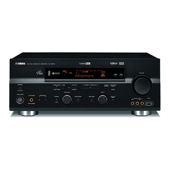
- Page 1 RX-N600 AV Receiver OWNER’S MANUAL...
-
Page 2: Important Safety Instructions
IMPORTANT SAFETY INSTRUCTIONS IMPORTANT SAFETY INSTRUCTIONS CAUTION RISK OF ELECTRIC SHOCK DO NOT OPEN CAUTION: TO REDUCE THE RISK OF ELECTRIC SHOCK, DO NOT REMOVE COVER (OR BACK). NO USER-SERVICEABLE PARTS INSIDE. REFER SERVICING TO QUALIFIED SERVICE PERSONNEL. • Explanation of Graphical Symbols The lightning flash with arrowhead symbol, within an equilateral triangle, is intended to alert you to the presence of uninsulated “dangerous voltage”... - Page 3 This product, when installed as indicated in the instructions contained in this manual, meets FCC requirements. Modifications not expressly approved by Yamaha may void your authority, granted by the FCC, to use the product. 2 IMPORTANT: When connecting this product to accessories and/or another product use only high quality shielded cables.
- Page 4 YAMAHA will not be held responsible for any damage resulting from use of this unit with a voltage other than specified.
-
Page 5: Table Of Contents
VCR or an STB... 19 Connecting a CD player, an MD player or a tape deck... 21 Connecting a YAMAHA iPod universal dock ... 22 Connecting the network... 23 Connecting a multi-format player, an external decoder or a sound processor... 24 Connecting a game console, a video camera or a portable audio player ... -
Page 6: Features
(such as YDS-10 sold separately), which supports iPod (Click and Wheel), iPod nano, and iPod mini Network features LAN port to connect a PC and YAMAHA MCX-2000 or access the Internet radio via a LAN DHCP automatic or manual network configuration... -
Page 7: Getting Started
Supplied accessories Check that you received all of the following parts. Remote control AM loop antenna CODE SET TRANSMIT POWER POWER STANDBY POWER SLEEP CD-R MULTI CH IN TUNER DOCK V-AUX SOURCE TV VOL TV CH VOLUME TV MUTE TV INPUT MUTE STEREO MUSIC... -
Page 8: Controls And Functions
CONTROLS AND FUNCTIONS CONTROLS AND FUNCTIONS Front panel Note The XM Satellite Radio controlling functions in the following buttons (SEARCH MODE, CATEGORY, PRESET/TUNING/CH l / h, MEMORY, and DISPLAY) are only applicable to the U.S.A. and Canada models and are operational only when “XM” is selected as the input source. - Page 9 8 TUNING MODE (AUTO/MAN’L) Switches between automatic tuning (the AUTO indicator is turned on) and manual tuning (the AUTO indicator is turned off) (see page 46). 9 ZONE 2 ON/OFF Turns on Zone 2 or sets it to the standby mode (see page 99).
-
Page 10: Remote Control
CONTROLS AND FUNCTIONS Remote control This section describes the function of each control on the remote control used to control this unit. To operate other components, see “REMOTE CONTROL FEATURES” on page 93. Notes • The operation mode of the remote control buttons in the shaded area below depends on the component selector switch position. Set the component selector switch to AMP to control this unit. - Page 11 L Network and USB input selector buttons Select the sub input source of NET/USB (see page 103). PC/MCX Selects a PC server or YAMAHA MCX-2000 as the sub input source of NET/USB. NET RADIO Selects the Internet radio as the sub input source of NET/USB.
-
Page 12: Using The Remote Control
CONTROLS AND FUNCTIONS Controlling the TUNER functions Set the component selector switch to SOURCE and then press TUNER to select “TUNER” as the input source. 4 Numeric buttons Use numbers 1 through 8 to select preset stations. 7 BAND Switches the reception band between FM and AM. 8 Cursor buttons u / d / j / i Press j / i to select a preset station group (A to E) and u / d to select a preset station number (1 to 8) -
Page 13: Front Panel Display
SILENT CINEMA HiFi DSP ZONE2 NIGHT 6 DOCK indicator Lights up when you station your iPod in a YAMAHA iPod universal dock (such as YDS-10 sold separately) connected to the DOCK terminal of this unit (see page 22). 7 SILENT CINEMA indicator Lights up when headphones are connected and a sound field program is selected (see page 34). - Page 14 CONTROLS AND FUNCTIONS C VOLUME level indicator Indicates the current volume level. D PCM indicator Lights up when this unit is reproducing PCM (Pulse Code Modulation) digital audio signals. E STANDARD indicator Lights up when the “SUR. STANDARD” or “SUR. ENHANCED”...
-
Page 15: Rear Panel
8 XM jack (U.S.A. and Canada models only) See page 54 for connection information. 9 DOCK terminal Use to connect a YAMAHA iPod universal dock (such as YDS-10 sold separately) where your iPod can be stationed. See page 22 for connection information. -
Page 16: Connections
Subwoofer (SW) The use of a subwoofer with a built-in amplifier, such as the YAMAHA Active Servo Processing Subwoofer System, is effective not only for reinforcing bass frequencies from any or all channels, but also for high fidelity reproduction of the LFE (low-frequency effect) channel included in Dolby Digital and DTS sources. -
Page 17: Connecting Speakers
Connecting speakers Be sure to connect the left channel (L), right channel (R), “+” (red) and “–” (black) properly. If the connections are faulty, no sound will be heard from the speakers, and if the polarity of the speaker connections is incorrect, the sound will be unnatural and lack bass. - Page 18 Connect surround speakers (4, 5) to these terminals. SURROUND BACK terminals Connect a surround back speaker (6) to these terminals. SUBWOOFER OUTPUT jack Connect a subwoofer with a built-in amplifier (7) (such as the YAMAHA Active Servo Processing Subwoofer System) to this jack. Speaker layout...
- Page 19 Connecting the speaker cable Remove approximately 10 mm (0.4 in) of insulation from the end of each speaker cable and then twist the exposed wires of the cable together to prevent short circuits. 10 mm (0.4 in) Loosen the knob. Red: positive (+) Black: negative (–) Insert one bare wire into the hole on the side...
-
Page 20: Information On Jacks And Cable Plugs
CONNECTIONS Information on jacks and cable plugs Audio jacks and cable plugs AUDIO DIGITAL AUDIO COAXIAL (White) (Red) (Orange) Left and right Coaxial analog audio digital audio cable plugs cable plug Audio jacks This unit has three types of audio jacks. Connection depends on the availability of audio jacks on your other components. -
Page 21: Audio And Video Signal Flow
Audio and video signal flow Audio signal flow for AUDIO OUT (REC) DIGITAL AUDIO COAXIAL DIGITAL AUDIO OPTICAL AUDIO Digital output Analog output Note This unit handles digital and analog signals independently. Thus, audio signals input at the analog jacks are output only at the analog AUDIO OUT (REC) jacks. -
Page 22: Connecting A Tv
CONNECTIONS Connecting a TV Connect your TV to the VIDEO MONITOR OUT jack, the S VIDEO MONITOR OUT jack or the COMPONENT VIDEO MONITOR OUT jacks of this unit. CAUTION Do not connect this unit or other components to the AC power supply until all connections between components are complete. -
Page 23: Connecting A Dvd Player, A Dvd Recorder, A Vcr Or An Stb
Connecting a DVD player, a DVD recorder, a VCR or an STB Connect your DVD player, DVD recorder, VCR or STB (set-top box) using the same type of video connections as those made for your TV (see page 18). The cable TV receiver and the satellite receiver are examples of the STB. CAUTION Do not connect this unit or other components to the AC power supply until all connections between components are complete. - Page 24 CONNECTIONS Connecting a DVD recorder or a VCR AUDIO VIDEO S VIDEO Connecting an STB AUDIO DTV/CBL DTV/CBL VIDEO S VIDEO DVD recorder or Cable TV receiver or satellite receiver DIGITAL INPUT DTV/CBL OPTICAL (U.S.A. model) COMPONENT VIDEO Component video out Component video out (U.S.A.
-
Page 25: Connecting A Cd Player, An Md Player Or A Tape Deck
Connecting a CD player, an MD player or a tape deck Connect your CD player, MD player or tape deck via analog and/or digital connections. CAUTION Do not connect this unit or other components to the AC power supply until all connections between components are complete. -
Page 26: Connecting A Yamaha Ipod Universal Dock
DOCK terminal of this unit as long as this unit is turned on. • Depending on the type of iPod, you may need to insert one of the iPod adapters supplied with a YAMAHA iPod universal dock (such as YDS-10 sold separately) into the dock slot before you station your iPod. -
Page 27: Connecting The Network
Configuration Protocol) server function. The following diagram shows a connection example where this unit is connected to one of the LAN ports on a 4-port router. To enjoy music files saved on your PC and YAMAHA MCX-2000 or access the Internet radio, each device must be connected properly in the network. -
Page 28: Connecting A Multi-Format Player, An External Decoder Or A Sound Processor
CONNECTIONS Connecting a multi-format player, an external decoder or a sound processor This unit is equipped with 6 additional input jacks (FRONT L/R, CENTER, SURROUND L/R and SUBWOOFER) for discrete multi-channel input from a multi-format player, external decoder or sound processor. Connect the output jacks on your multi-format player, external decoder or sound processor to the MULTI CH INPUT jacks. -
Page 29: Connecting The Fm And Am Antennas
• A properly installed outdoor antenna provides clearer reception than an indoor one. If you experience poor reception quality, install an outdoor antenna. Consult the nearest authorized YAMAHA dealer or service center about outdoor antennas. AM loop antenna (supplied) Indoor FM antenna... -
Page 30: Connecting The Power Cable
CONNECTIONS Connecting the power cable Once all connections are complete, plug the power cable into the AC wall outlet. VOLTAGE SELECTOR (General model only) CAUTION The VOLTAGE SELECTOR on the rear panel of this unit must be set for your local voltage BEFORE plugging the power cable into the AC wall outlet. -
Page 31: Setting The Speaker Impedance
Setting the speaker impedance CAUTION If you are to use 6 ohm speakers, set “SP IMP.” to “6 MIN” as follows BEFORE using this unit. 4 ohm speakers can be also used as the front speakers. MASTER PRESET/TUNING FM/AM A/B/C/D/E l PRESET/TUNING/CH h MEMORY EDIT... -
Page 32: Turning On And Off The Power
CONNECTIONS Turning on and off the power When all connections are complete, turn on this unit. MASTER ON/OFF MASTER PRESET/TUNING FM/AM A/B/C/D/E EDIT NEXT SEARCH MODE CATEGORY PROGRAM MAIN ZONE PHONES SPEAKERS STRAIGHT TONE CONTROL ON/OFF EFFECT SILENT CINEMA MAIN ZONE ON/OFF Turning on this unit Press MASTER ON/OFF on the front panel inward to the ON position to turn on this unit. -
Page 33: Basic Setup
The “BASIC SETUP” feature is a useful way to set up your system quickly and with minimal effort. Notes • Make sure you disconnect your headphones from this unit. • If you wish to configure this unit manually using more precise adjustments, use the detailed parameters in “SOUND MENU” (see page 77). - Page 34 BASIC SETUP Press d to select “SUBWOOFER” and then j / i to select the desired setting. PRESET/CH . SUBWOOFER;;;;YES ENTER A-E/CAT. A-E/CAT. Choices: YES, NONE • Select “YES” if you have a subwoofer in your system. • Select “NONE” if you do not have a subwoofer in your system.
- Page 35 Press j / i to select the desired setting. ;BASIC SETUP PRESET/CH ROOM: SUBWOOFER;;;;YES SPEAKERS;;;;6spk ENTER SETUP:>OK CANCEL . CHECK OK?;;;;YES A-E/CAT. A-E/CAT. [<]/[>]:Select Choices: YES, NO • Select “YES” to complete the setup procedure if the test tone levels from each speaker were satisfactory.
-
Page 36: Playback
PLAYBACK CAUTION Extreme caution should be exercised when you play back CDs encoded in DTS. If you play back a CD encoded in DTS on a DTS-incompatible CD player, you will only hear some unwanted noise that may damage your speakers. Check whether your CD player supports CDs encoded in DTS. Also, check the sound output level of your CD player before you play back a CD encoded in DTS. - Page 37 Rotate VOLUME on the front panel (or press VOLUME +/– on the remote control) to adjust the volume to the desired output level. VOLUME Front panel Press TONE CONTROL on the front panel repeatedly to select “TREBLE” or “BASS” and then rotate the PROGRAM selector to adjust the corresponding frequency response level.
-
Page 38: Using Audio Features
USING AUDIO FEATURES Using SILENT CINEMA SILENT CINEMA allows you to enjoy multi-channel music or movie sound, including Dolby Digital and DTS sources, through ordinary headphones. SILENT CINEMA activates automatically whenever you connect headphones to the PHONES jack while listening to a source with a CINEMA DSP or HiFi DSP sound field program (see page 66). -
Page 39: Selecting The Input Mode
“NIGHT:CINEMA” and “NIGHT:MUSIC” adjustments are stored independently. Notes • You cannot use the night listening modes in the following cases: – when the “DIRECT STEREO” mode (see page 39) is selected. – when the component connected to the MULTI CH INPUT jacks is selected as the input source (see page 38). -
Page 40: Adjusting The Speaker Level
USING AUDIO FEATURES Press SLEEP on the remote control repeatedly to set the amount of time. Each time you press SLEEP, the front panel display changes as shown below. SLEEP SLEEP 120min SLEEP 90min SLEEP OFF SLEEP 30min The SLEEP indicator flashes while you are switching the amount of time for the sleep timer. -
Page 41: Selecting The Compressed Music Enhancer Mode
Press j / i on the remote control to adjust the speaker output level. • Press i to increase the value. • Press j to decrease the value. Control range: –10 dB to +10 dB PRESET/CH ENTER A-E/CAT. A-E/CAT. This operation can also be performed using the control buttons on the front panel. -
Page 42: Selecting The Multi Ch Input Component
USING AUDIO FEATURES Set the component selector switch to AMP and then press ENHANCER on the remote control repeatedly to select the desired Compressed Music Enhancer mode. The following display appears in the OSD and the ENHANCER indicator lights up in the front panel display. -
Page 43: Enjoying Multi-Channel Sources In 2-Channel Stereo39
Enjoying multi-channel sources in 2-channel stereo You can mix down multi-channel sources to 2 channels and enjoy playback in 2-channel stereo. Set the component selector switch to AMP and then press STEREO on the remote control repeatedly to select “2ch Stereo”. STEREO SOURCE 2ch Stereo... -
Page 44: Using Video Features
USING VIDEO FEATURES Displaying the input source information You can display the format, sampling frequency, channel, bit rate and flag data of the current input signal. Set the component selector switch to AMP and then press SET MENU on the remote control. -
Page 45: Selecting The Osd Mode
Selecting the OSD mode You can display the operating information of this unit on a video monitor. If you display the “SET MENU” and sound field program parameter settings on a video monitor, it is much easier to see the available options and parameters than it is to read the information in the front panel display. -
Page 46: Enjoying Surround Sound
ENJOYING SURROUND SOUND ENJOYING SURROUND SOUND Enjoying multi-channel sources in 6.1-channel surround If you connected a surround back speaker, use this feature to enjoy 6.1-channel playback for multi-channel sources using the Dolby Pro Logic IIx, Dolby Digital EX or DTS-ES decoders. Set the component selector switch to AMP and then press EXTD SUR. -
Page 47: Enjoying 2-Channel Sources In Surround
Enjoying 2-channel sources in surround Signals input from 2-channel sources can also be played back on multi-channels. Set the component selector switch to AMP and then press STANDARD on the remote control repeatedly to switch between the “SUR. STANDARD” and “SUR. ENHANCED” programs or press MOVIE to select the “MOVIE THEATER”... -
Page 48: Using Virtual Cinema Dsp
ENJOYING SURROUND SOUND Using Virtual CINEMA DSP Virtual CINEMA DSP allows you to enjoy the CINEMA DSP programs without surround speakers. It creates virtual speakers to reproduce the natural sound field. If you set “SUR. L/R SP” NONE” (see page 78), to “... -
Page 49: Recording
Recording adjustments and other operations are performed from the recording components. Refer to the operating instructions for those components. CAUTION The DTS signal is a digital bitstream. Attempting to digitally record the DTS bitstream will result in noise being recorded. Therefore, if you want to use this unit to record sources encoded in DTS, the following considerations and adjustments need to be made. -
Page 50: Fm/Am Tuning
FM/AM TUNING There are 2 tuning methods: automatic and manual. Automatic tuning is effective when station signals are strong and there is no interference. If the signal from the station you want to select is weak, tune into it manually. You can also use the automatic and manual preset tuning features to store up to 40 stations (A1 to E8: 8 preset station numbers in each of the 5 preset station groups). -
Page 51: Manual Tuning
Manual tuning If the signal received from the station you want to select is weak, tune into it manually. Note Manually tuning into an FM station automatically switches the tuner to monaural reception to increase the signal quality. MASTER PRESET/TUNING FM/AM A/B/C/D/E l PRESET/TUNING/CH h... -
Page 52: Automatic Preset Tuning
FM/AM TUNING Automatic preset tuning You can use the automatic preset tuning feature to store FM stations with strong signals up to 40 (A1 to E8: 8 preset station numbers in each of the 5 preset station groups) of those stations in order. You can then recall any preset station easily by selecting the preset station number. -
Page 53: Manual Preset Tuning
Automatic preset tuning options You can specify the preset number from which this unit stores FM stations and/or begins tuning toward lower frequencies. Note First carry out steps 1 through 3 in “Automatic preset tuning” on page 48. • Press A/B/C/D/E and then PRESET/TUNING/ CH l / h to select the preset station number under which the first station will be stored. -
Page 54: Selecting Preset Stations
FM/AM TUNING Press PRESET/TUNING/CH l / h to select a preset station number (1 to 8) while the MEMORY indicator is flashing. • Press h to select a higher preset station number. • Press l to select a lower preset station number. l PRESET/TUNING/CH h LEVEL V-AUX... -
Page 55: Exchanging Preset Stations
Press PRESET/TUNING/CH l / h on the front panel (or PRESET/CH u / d on the remote control) to select the desired preset station number (1 to 8). The preset station group and number appear in the front panel display along with the station band and frequency. - Page 56 FM/AM TUNING Select preset station “A5” using A/B/C/D/E and PRESET/TUNING/CH l / h. “A5” and the MEMORY indicator flash in the front panel display. See “Selecting preset stations” on page 50. l PRESET/TUNING/CH h A/B/C/D/E NEXT CATEGORY V-AUX DTV/CBL A5:FM 90.6 MHz Flashes Press EDIT again.
-
Page 57: Xm ® Satellite Radio Tuning
® XM Satellite Radio is the satellite radio service with millions of listeners across the United States and Canada, broadcasting live daily. The XM Satellite Radio channel lineup includes over 160 digital channels of choice from coast to coast: 67 commercial-free music channels, featuring hip hop to opera, classical to country, bluegrass to blues; 33 channels of premier sports, talk, comedy, children’s and entertainment programming;... -
Page 58: Connecting Xm Passport System
XM® SATELLITE RADIO TUNING Connecting XM Passport System Connect XM Passport and XM Passport Home Dock (sold separately) to the XM jack on the rear panel of this unit. For details, see the operating instructions provided with XM Passport System. (U.S.A. -
Page 59: Xm Satellite Radio Controls And Functions
XM Satellite Radio controls and functions Note The following controls are available only when “XM” is selected as the input source. Rotate the INPUT selector on the front panel (or set the component selector switch to SOURCE and then press XM on the remote control) to select “XM” as the input source. Front panel functions (U.S.A. -
Page 60: Activating Xm Satellite Radio
XM® SATELLITE RADIO TUNING Activating XM Satellite Radio To sign up for an account with the XM Satellite Radio service, an XM Satellite Radio ID number is required. Follow the procedure below to check your ID number, and then visit the website or call toll-free with a major credit card handy for signing up. -
Page 61: Basic Xm Satellite Radio Operations
Basic XM Satellite Radio operations (U.S.A. model) MASTER PRESET/TUNING FM/AM A/B/C/D/E l PRESET/TUNING/CH h MEMORY EDIT MAN'L/AUTO FM NEXT LEVEL SEARCH MODE CATEGORY PROGRAM INPUT MAIN ZONE PHONES SPEAKERS STRAIGHT TONE CONTROL INPUT MODE ON/OFF EFFECT SILENT CINEMA SLEEP CD-R MULTI CH IN TUNER DOCK... -
Page 62: Selecting The Xm Satellite Radio Search Mode
XM® SATELLITE RADIO TUNING Selecting the XM Satellite Radio search mode You can search for the desired channel using one of the three search modes (All Channel Search, Category Search, and Preset Search modes). You can also enter the channel number directly to select the desired channel by using the Direct Number Access mode (see page 61). - Page 63 Category Search mode (U.S.A. model) MASTER PRESET/TUNING FM/AM A/B/C/D/E l PRESET/TUNING/CH h MEMORY EDIT MAN'L/AUTO FM NEXT LEVEL SEARCH MODE CATEGORY PROGRAM INPUT MAIN ZONE PHONES SPEAKERS STRAIGHT TONE CONTROL INPUT MODE ON/OFF EFFECT SILENT CINEMA STEREO MUSIC SLEEP CD-R MULTI CH IN STANDARD SELECT...
-
Page 64: Preset Search Mode
XM® SATELLITE RADIO TUNING Preset Search mode Prior to selecting a preset channel in the Preset Search mode, you must preset XM Satellite Radio channels. For details, see “Setting the XM Satellite Radio preset channels” on page 62. All preset channels (A1 to E8) recalls “001 Preview” by the initial factory setting. - Page 65 Direct Number Access mode STEREO SLEEP CD-R MULTI CH IN STANDARD TUNER DOCK SPEAKERS V-AUX LEVEL TITLE SOURCE BAND TV VOL TV CH VOLUME A-E/CAT. RETURN TV MUTE TV INPUT MUTE XM MEMORY STEREO MUSIC ENTERTAIN MOVIE (U.S.A. model) Set the component selector switch to SOURCE and then press XM on the remote control to select “XM”...
-
Page 66: Setting The Xm Satellite Radio Preset Channels
XM® SATELLITE RADIO TUNING Setting the XM Satellite Radio preset channels You can use this feature to store up to 40 XM Satellite Radio channels (A1 to E8: 8 preset channel numbers in each of the 5 preset channel groups). You can then recall any preset channel easily by selecting the preset channel group and number as described in “Preset Search mode”... -
Page 67: Displaying The Xm Satellite Radio Information
Press PRESET/TUNING/CH l / h on the front panel (or PRESET/CH u / d on the remote control) repeatedly to select a preset channel number (1 to 8) while the MEMORY indicator is flashing. The preset channel number appears in the front panel display. - Page 68 XM® SATELLITE RADIO TUNING When the channel number / name is displayed: V-AUX DTV/CBL [043] XMU When the channel category is displayed: V-AUX DTV/CBL <CAT>Rock When the artist name / song title is displayed: V-AUX DTV/CBL Coldplay / Spe • The front panel display can indicate up to 14 alphanumeric characters at once.
-
Page 69: Sound Field Programs
The acoustics in your room could be changed to those of a concert hall, a dance floor, or a room with virtually any size at all. This ability to create sound fields at will is exactly what YAMAHA has done with the digital sound field processor. -
Page 70: Sound Field Program Descriptions
(DSP) chip containing several sound field programs which you can use to enhance your playback experience. The YAMAHA CINEMA DSP modes are compatible with all Dolby Digital, DTS, and Dolby Surround sources. Set “INPUT MODE” to “AUTO” (see page 35) to enable this unit to automatically switch to the appropriate digital decoder according to the input signal. -
Page 71: For Music Sources
Remote control Sound field program button MOVIE THEATER Spectacle MOVIE THEATER Sci-Fi MOVIE THEATER Adventure MOVIE THEATER General SUR. STANDARD SUR. ENHANCED For music sources You can select from the following sound fields when playing music sources, like CD, FM/AM broadcasting, tapes, etc. Rotate the PROGRAM selector on the front panel (or set the component selector switch to AMP and then press one of the sound field program selector buttons on the remote control) to select the desired sound field program (see page 65). -
Page 72: Changing Sound Field Parameter Settings
SOUND FIELD PROGRAMS Changing sound field parameter settings You can enjoy good quality sound with the initial factory settings. Although you do not have to change the initial factory settings, you can change some of the parameters to better suit the input source or your listening room. Notes •... -
Page 73: Sound Field Parameter Descriptions
Sound field parameter descriptions You can adjust the values of certain digital sound field parameters so that the sound fields are recreated accurately in your listening room. Not all of the following parameters are found in every program. To change sound field parameter settings to suit your listening environment, see page 68 for details. Sound field parameter DSP LEVEL DSP level. - Page 74 SOUND FIELD PROGRAMS Sound field parameter ROOM SIZE Room size. Presence, surround, and surround back room sizes. Adjusts the apparent size of the surround sound field. The larger the value, the larger the surround sound field becomes. As the P.ROOM SIZE sound is repeatedly reflected around a room, the larger the hall is, the longer the time between S.ROOM SIZE the original reflected sound and the subsequent reflections.
- Page 75 Sound field parameter REV.TIME Reverberation time. Adjusts the amount of time taken for the dense, subsequent reverberation sound to decay by 60 dB at 1 kHz. This changes the apparent size of the acoustic environment over an extremely wide range. Set a longer reverberation time for “dead” sources and listening room environments, and a shorter time for “live”...
- Page 76 SOUND FIELD PROGRAMS Sound field parameter REV.LEVEL Reverberation level. Adjusts the volume of the reverberation sound. The larger the value, the stronger the reverberation becomes. Control range: 0 to 100% 2ch Stereo 2-channel stereo direct. Bypasses the decoders and DSP processors of this unit for pure hi-fi stereo sound when playing 2-channel analog sources.
- Page 77 Sound field parameter PRO LOGIC IIx Music Pro Logic IIx Music and Pro Logic II Music panorama. Sends stereo signals to the surround speakers as well as the front speakers for a wraparound effect. PRO LOGIC II Music PANORAMA Choices: OFF, ON PRO LOGIC IIx Music Pro Logic IIx Music and Pro Logic II Music dimension.
-
Page 78: Set Menu
SET MENU You can use the following parameters in “SET MENU” to adjust a variety of system settings and customize the way this unit operates. Change the initial settings (indicated in bold under each parameter) to reflect the needs of your listening environment. - Page 79 Network and USB menu 3 NET/USB MENU Use this menu to manually adjust the network and USB system parameters. Parameter A)NETWORK Configures the network settings automatically or manually. B)PLAY STYLE Adjusts the playback style. C)INFORMATION Displays the network system information. Option menu 4 OPTION MENU Use this menu to manually adjust the optional system parameters.
-
Page 80: Using Set Menu
SET MENU Using SET MENU Use the remote control to access and adjust each parameter. STEREO SLEEP CD-R STANDARD MULTI CH IN TUNER DOCK SPEAKERS V-AUX LEVEL TITLE SOURCE BAND TV VOL TV CH VOLUME A-E/CAT. RETURN TV MUTE TV INPUT MUTE XM MEMORY STEREO... -
Page 81: Sound Menu
Press u / d repeatedly and then press ENTER to select and enter the desired submenu. The following display is an example where “SPEAKER LEVEL” is selected. PRESET/CH ENTER A-E/CAT. A-E/CAT. A-E/CAT. B)SPEAKER LEVEL -__________+ FL;;;;;;;;;; FR;;;;;;;;;; C;;;;;;;;;; Press u / d to select the desired parameter and then j / i to change the parameter settings. - Page 82 SET MENU Center speaker CENTER SP Choices: NONE, SML, LRG CENTER SP NONE >SML • Select “NONE” (none) if you did not connect a center speaker. The center channel signals are directed to the front left and right speakers. • Select “SML” (small) if you have a small center speaker that does not reproduce low-frequency signals effectively.
- Page 83 CROSSOVER Crossover Use this feature to select a crossover frequency of all the speakers set to “SML” (or “SMALL”) or to “NONE” in “SPEAKER SET” (see pages 77 and 78). All frequencies below the selected frequency will be sent to the subwoofer or to the speakers set to “LRG”...
- Page 84 SET MENU Speaker distance C)SP DISTANCE Use this feature to manually adjust the distance of each speaker and the delay applied to the respective channel. Ideally, each speaker should be the same distance from the main listening position. However, this is not possible in most home situations.
- Page 85 Dynamic range F)DYNAMIC RANGE Use this feature to select the amount of dynamic range compression to be applied to your speakers or headphones. This setting is effective only when this unit is decoding Dolby Digital and DTS signals. F)DYNAMIC RANGE .
-
Page 86: Input Menu
SET MENU 2 INPUT MENU Use this menu to reassign the input/output jacks, select the input mode or rename the input source. 2 INPUT MENU . A)I/O ASSIGNMENT B)INPUT MODE C)INPUT RENAME D)VOLUME TRIM [ ]/[ ]:Up/Down [ENTER]:Enter Input/output assignment A)I/O ASSIGNMENT Use this feature to assign the input/output jacks according to the component to be used if the initial settings of this... - Page 87 Input mode B)INPUT MODE Use this feature to set this unit to reset “INPUT MODE” back to “AUTO” (see page 35) regardless of the previous setting or to recall the last input mode (“AUTO”, “DTS”, or “ANALOG”) used for that source whenever you turn on this unit.
-
Page 88: Net/Usb Menu
SET MENU Volume trim D)VOLUME TRIM Use this feature to adjust the level of the signal input at each jack. This is useful if you want to balance the level of each input source to avoid sudden changes in volume when switching between input sources. - Page 89 Primary DNS server DNS (P) Secondary DNS server DNS (S) Use this parameter to specify the IP address of the primary and secondary DNS (Domain Name System) servers. Note If you have only one DNS address, enter the DNS address in “DNS (P)”.
-
Page 90: Option Menu
SET MENU Network information C)INFORMATION Use this feature to display the network system information. C)INFORMATION MAC ADDRESS XX:XX:XX:XX:XX:XX STATUS 10BASE-T FULL-DUPLEX [ENTER]:Return Note The above display is an example. MAC (Media Access Control) address MAC ADDRESS This information displays the MAC address that is assigned to this unit. - Page 91 OSD shift OSD SHIFT Use this feature to adjust the vertical position of the OSD. Control range: –5 (upward) to +5 (downward) Control step: 1 Initial setting: 0 • Press j to raise the position of the OSD. • Press i to lower the position of the OSD. Gray back GRAY BACK Use this feature to display a gray background in the OSD when there is no video signal being input.
- Page 92 SET MENU Parameter initialization Use this feature to initialize the parameters of each sound field program within a sound field program group. When you initialize a sound field program group, all of the parameter values within that group revert to their initial factory settings.
- Page 93 XM Radio setting E)XM RADIO SET (U.S.A. and Canada models only) E)XM RADIO SET . XM ANTENNA;;NONE [ENTER]:Return Radio antenna XM ANTENNA Use this feature to check the current reception level of XM Passport System connected to the XM jack of this unit (see page 54).
-
Page 94: Advanced Setup
ADVANCED SETUP This unit has additional menus that are displayed in the front panel display. The advanced setup menu offers additional operations to adjust and customize the way this unit operates. Change the initial settings (indicated in bold under each parameter) to reflect the needs of your listening environment. - Page 95 • When the network settings are reset, “DHCP” in “NET/USB MENU” is automatically set to “ON” (see page 84) and the registered client ID of this unit on your YAMAHA MCX-2000 is cleared (see page 105). Remote control AMP ID Use this feature to set the AMP ID of this unit for remote control recognition (see page 96).
- Page 96 ADVANCED SETUP Remote control TUNER ID Use this feature to set the TUNER ID of this unit for remote control recognition (see page 96). Choices: ID1, ID2 • Select “ID1” when the remote control TUNER ID library code is set to “81916”. •...
-
Page 97: Remote Control Features
REMOTE CONTROL FEATURES In addition to controlling this unit, the remote control can also operate other audiovisual components made by YAMAHA and other manufacturers. To control your TV or other components, you must set the appropriate remote control code for each input source (see page 95). -
Page 98: Controlling Other Components
REMOTE CONTROL FEATURES Controlling other components Set the component selector switch to SOURCE to control other components selected with the input selector buttons . You must set the appropriate remote control code for each input source (see page 95). The following table shows the function of each control button used to control other components assigned to each input selector button . -
Page 99: Setting The Remote Control Code
Note You may not be able to operate your YAMAHA component even if a YAMAHA remote control code is initially set as listed above. In this case, try setting other YAMAHA remote control codes. Press one of the input selector buttons or... -
Page 100: Setting Library Codes
REMOTE CONTROL FEATURES Setting library codes You can operate multiple YAMAHA receivers or amplifiers in the same room with the supplied remote control simultaneously. Set the appropriate library code to select and operate the desired component with the supplied remote control. -
Page 101: Resetting All Remote Control Codes
• You need to set the corresponding remote control XM ID of this unit in the advanced setup (see page 92). • When using multiple YAMAHA receivers/amplifiers, you may be able to operate the other components simultaneously with the default code setting. In this case, set one of the alternative codes to operate this unit separately. -
Page 102: Using Multi-Zone Configuration
YAMAHA dealer or service center about the Zone 2 connections that best meet your requirements. • Some YAMAHA models are able to connect directly to the REMOTE jacks of this unit. If you own these products, you may not need to use an infrared signal emitter. -
Page 103: Controlling Zone 2
(U.S.A. and Canada models only) • Enjoying music stored on your iPod stationed in a YAMAHA iPod universal dock (such as YDS-10 sold separately) connected to the DOCK terminal of this unit when “V-AUX” is selected as the input source (see page 101) The volume level and tonal quality of Zone 2 cannot be adjusted. - Page 104 USING MULTI-ZONE CONFIGURATION Setting the remote control to the Zone 2 mode Note The remote control is originally set to the main mode to control the main zone. To control Zone 2 with the remote control, you must first set the remote control to the Zone 2 mode. Press CODE SET using a ballpoint pen or a similar object.
-
Page 105: Using Ipod
Once you have stationed your iPod in a YAMAHA iPod universal dock (such as YDS-10 sold separately) connected to the DOCK terminal of this unit (see page 22), you can enjoy playback of your iPod using the supplied remote control. - Page 106 USING iPod® Press DISPLAY on the remote control. The following display appears in the OSD. iPod Playlists Artists Albums DISPLAY Songs ON SCREEN Genres Composers Setup Press u / d / j / i on the remote control to navigate the iPod menu and then press ENTER to begin playback of the selected song.
-
Page 107: Using Network/Usb Features
This unit is equipped with network and USB features that allow you to enjoy WAV (PCM format only), MP3 and WMA files saved on your PC, YAMAHA MCX-2000, USB memory device and USB portable audio player or access the Internet radio. - Page 108 USING NETWORK/USB FEATURES The following procedure shows the basic steps to navigate the network and USB menus. See pages 105 and 106 for details about each sub input source. Note “Please wait” may appear whenever it takes time for communication. This is not a system malfunction. Wait for a while.
-
Page 109: Using A Pc Server Or Yamaha Mcx-2000
Select a desired PC server or MCX-2000 to begin playback. Notes • YAMAHA MCX-2000 may not be for sale in some locations. • You can connect this unit to up to 4 PC servers and 1 MCX-2000, and each server must be connected to the same subnet as this unit. -
Page 110: Using The Internet Radio
Registering this unit on the YAMAHA MCX-2000 You must register this unit on your YAMAHA MCX-2000 so that this unit can be recognized by your YAMAHA MCX-2000. For details, refer to the operation manual supplied with your YAMAHA MCX-2000. Turn off this unit. -
Page 111: Using A Usb Memory Device Or A Usb Portable Audio Player
Using a USB memory device or a USB portable audio player Use this feature to enjoy WAV (PCM format only), MP3 and WMA files saved on your USB memory device or USB portable audio player connected to the USB port on the front panel of this unit. -
Page 112: Resetting The System
RESETTING THE SYSTEM Use this feature to reset all the parameters of this unit to the initial factory settings. Notes • This procedure completely resets all the parameters of this unit including the “SET MENU” parameters. However, the advanced setup menu parameters will not be initialized. -
Page 113: Troubleshooting
Refer to the table below when this unit does not function properly. If the problem you are experiencing is not listed below or if the instruction below does not help, turn off this unit, disconnect the power cable, and contact the nearest authorized YAMAHA dealer or service center. General... - Page 114 TROUBLESHOOTING Problem The sound suddenly The protection circuitry has been activated goes off. because of a short circuit, etc. The sleep timer has turned off this unit. The sound is muted. Sound is heard from Incorrect cable connections. the speaker on one side only.
- Page 115 Problem Dolby Digital or DTS The connected component is not set to sources cannot be output Dolby Digital or DTS digital played. (Dolby Digital signals. or DTS indicator in “INPUT MODE” is set to “ANALOG”. the front panel display does not light up.) A humming sound is Incorrect cable connections.
- Page 116 TROUBLESHOOTING Tuner Problem FM stereo reception is noisy. There is distortion, and clear reception cannot be obtained even with a good FM antenna. The desired station cannot be tuned into with the automatic tuning method. Previously preset stations can no longer be tuned into.
- Page 117 Match the remote control ID of this unit with the corresponding remote control library code. Cause Turn off this unit and reconnect the YAMAHA iPod universal dock to the DOCK terminal of this unit. Try resetting your iPod. Only iPod (Click and Wheel), iPod nano, and iPod mini are supported.
- Page 118 TROUBLESHOOTING Network and USB Problem The PC server/MCX-2000/ The IP address is not set properly. Internet radio does not function properly. The network cable is not connected. The music in the PC The PC does not have Windows Media server cannot be played Connect 2.0 installed in it.
- Page 119 Status message Please wait This unit is in the middle of recognizing the connection with your network. This unit is in the middle of recognizing the connection with your USB memory device or USB portable audio player. Please wait This unit is in the middle of waking up MCX-2000 that has been set to the (Starting Server) standby mode.
-
Page 120: Glossary
GLOSSARY Audio information Dolby Digital Dolby Digital is a digital surround sound system that gives you completely independent multi-channel audio. With 3 front channels (front L/R and center), and 2 surround stereo channels, Dolby Digital provides 5 full-range audio channels. With an additional channel especially for bass effects, called LFE (Low Frequency Effect), the system has a total of 5.1-channels (LFE is counted as 0.1 channel). - Page 121 LFE 0.1 channel This channel reproduces low-frequency signals. The frequency range of this channel is from 20 Hz to 120 Hz. This channel is counted as 0.1 because it only enforces a low-frequency range compared to the full-range reproduced by the other 5/6 channels in Dolby Digital or DTS 5.1/6.1-channel systems.
-
Page 122: Video Information
SILENT CINEMA YAMAHA has developed a natural, realistic sound effect DSP algorithm for headphones. Parameters for headphones have been set for each sound field so that accurate representations of all the sound field programs can be enjoyed on headphones. -
Page 123: Specifications
– and, most importantly, without affecting your sensitive hearing. Since hearing damage from loud sounds is often undetectable until it is too late, YAMAHA and the Electronic Industries Association’s Consumer Electronics Group recommend you to avoid prolonged exposure from excessive volume levels. -
Page 124: Gnu General Public License
GNU GENERAL PUBLIC LICENSE Version 2, June 1991 Copyright (C) 1989, 1991 Free Software Foundation, Inc. 59 Temple Place, Suite 330, Boston, MA 02111-1307 USA Everyone is permitted to copy and distribute verbatim copies of this license document, but changing it is not allowed. Preamble The licenses for most software are designed to take away your freedom to share and change it. - Page 125 This section is intended to make thoroughly clear what is believed to be a consequence of the rest of this License. If the distribution and/or use of the Program is restricted in certain countries either by patents or by copyrighted interfaces, the original copyright holder who places the Program under this License may add an explicit geographical distribution limitation excluding those countries, so that distribution is permitted only in or among countries not thus excluded.
- Page 126 In other cases, permission to use a particular library in non-free programs enables a greater number of people to use a large body of free software. For example, permission to use the GNU C Library in non-free programs enables many more people to use the whole GNU operating system, as well as its variant, the GNU/Linux operating system.
- Page 127 It may happen that this requirement contradicts the license restrictions of other proprietary libraries that do not normally accompany the operating system. Such a contradiction means you cannot use both them and the Library together in an executable that you distribute. You may place library facilities that are a work based on the Library side-by-side in a single library together with other library facilities not covered by this License, and distribute such a combined library, provided that the separate distribution of...
-
Page 128: List Of Remote Control Codes
LIST OF REMOTE CONTROL CODES MOTOROLA CABLE TV RECEIVER PACE 10003, 10008, PIONEER 10014, 10017, 10033 SCIENTIFIC ATLANTA AMERICAST 10899 BELL & HOWELL SONY 10014 SUPERCABLE BELL SOUTH 10899 CLEARMASTER THOMSON 10883 ZENITH CLEARMAX 10883 COOLMAX 10883 DIGEO 11187 DBS/PVR DIGI 10637 COMBINATION... - Page 129 20885, 21755 VIZIO 20864, 20885, 21756 WARDS 20030, 20054, 20080, 20111, 20178, 20866, 21156 WAYCON 20156 WESTINGHOUSE 20451, 20889 WHITE WESTINGHOUSE 20463, 20623 YAMAHA 20030, 20650, 20769, 20833, 20839, 21405, 21406, 21407 ZENITH 20017, 20092, 20178, 20463, 21145, 21904, 21929 APPENDIX-vi...
-
Page 130: Dvd Player
VIEWSONIC 31972 VOODOO 31972 WARDS 30035, 30042, 30047, 30048, 30060, 30072, 30081, 30149, 30240 WHITE WESTINGHOUSE 30072, 30209 XR-1000 30035, 30072 YAMAHA 30038 ZENITH 30033, 30039, 30209, 30479, 31139 ZT GROUP 31972 DVD PLAYER ADCOM 41094 ADVENT 41016 AIWA 40641... -
Page 131: Dvd Recorder
URBAN CONCEPTS MINTEK 40717, 40839 MITSUBISHI 40521, 41521 US LOGIC MOMITSU 41082 VENTURER MYRYAD 40894 VIZIO 40591, 40692, XBOX 40741 YAMAHA NAKAMICHI 41222 40785 YAMAKAWA 40872 NESA 40717 ZENITH NEXT BASE 40826 NORCENT 40872, 41003, ZOECE 41107, 41265 ONKYO 40503, 40627,... -
Page 132: Tape Deck
YAMAHA ELECTRONICS (UK) LTD. YAMAHA HOUSE, 200 RICKMANSWORTH ROAD WATFORD, HERTS WD18 7GQ, ENGLAND YAMAHA SCANDINAVIA A.B. J A WETTERGRENS GATA 1, BOX 30053, 400 43 VÄSTRA FRÖLUNDA, SWEDEN YAMAHA MUSIC AUSTRALIA PTY, LTD. 17-33 MARKET ST., SOUTH MELBOURNE, 3205 VIC., AUSTRALIA...