Advertisement
Available languages
Available languages
Quick Links
Advertisement

Related Manuals for Yamaha RX-596


Summary of Contents for Yamaha RX-596
- Page 1 OWNER'S MANUAL...
- Page 2 • Explanation of Graphical Symbols The lightning flash with arrowhead symbol, within an equilateral triangle, RISKOF ELECTRIC SHOCK is intended to alert you to the DO NOT OPEN presence of uninsulated "dangerous voltage" within the product's enclosure that may be of sufficient CAUTION: TO REDUCE THE RISK OF magnitude...
- Page 3 Consumer Electronics Group want you to get the most out of undetectable until it is too late, YAMAHA and the Electronic Industries Association's Consumer your equipment by playing it at a safe level.
- Page 4 @ 40-Station Random Access Preset Tuning @ 80W + 80W (8_) RMS Output Power, 0.025% THD, 20-20,000 @ Automatic Preset Tuning @ 90W + 90W (GO) RMS Output @ Preset Station Shifting Capability (Preset Power, 0.05% THD, 20-20,000 Editing) @ High Dynamic Power, Low _mpedance @ _F Count...
- Page 5 After unpacking, check that the following parts are included, Indoor FM Antenna Remote Control Transmitter AM Loop Antenna Antenna adapter (U,S.A, and Canada models only) Batteries (size AA, R6, UMo3)
- Page 6 To assure the finest performance, please read this manual This unit is not disconnected from the AC power source carefully. Keep it in a safe place for future reference. long as it is connected to the wall outlet, even if this unit itself is turned off.
- Page 7 Battery installation Remote control transmitter operation range oooo¢OO control sensor Within approximately 6 m (19 7 feet) 30° Battery rep{acement if you find that the remote control transmitter must be used closer to the main unit, the batteries are weak. Replace both batteries...
- Page 8 L, R (right) to R, '+" to "+" and '-" to "-'L Also, refer to the owner's manual for each component to be connected to this unit. * If you have YAMAHA components numbered 3, 4, etc. on the rear panel, connections can be made easily only by...
- Page 9 CONNECTING SPEAKERS Notes Connect the SPEAKERS terminals to your speakers with wire of the proper gauge (cut as short as possible). If the ® One or two speaker systems can be connected to this unit. connections are faulty, no sound will be heard from the If you connect only one speaker system,...
-
Page 10: Gnd Terminal
ANTENNA CONNECTIONS ® Each antenna should be connected to the designated terminal(s) correctly, referring to the following diagram. ® Both AM and FM indoor antennas are supplied to this unit. In general, these antennas will provide sufficient signal strength. Nevertheless, a properly installed outdoor... -
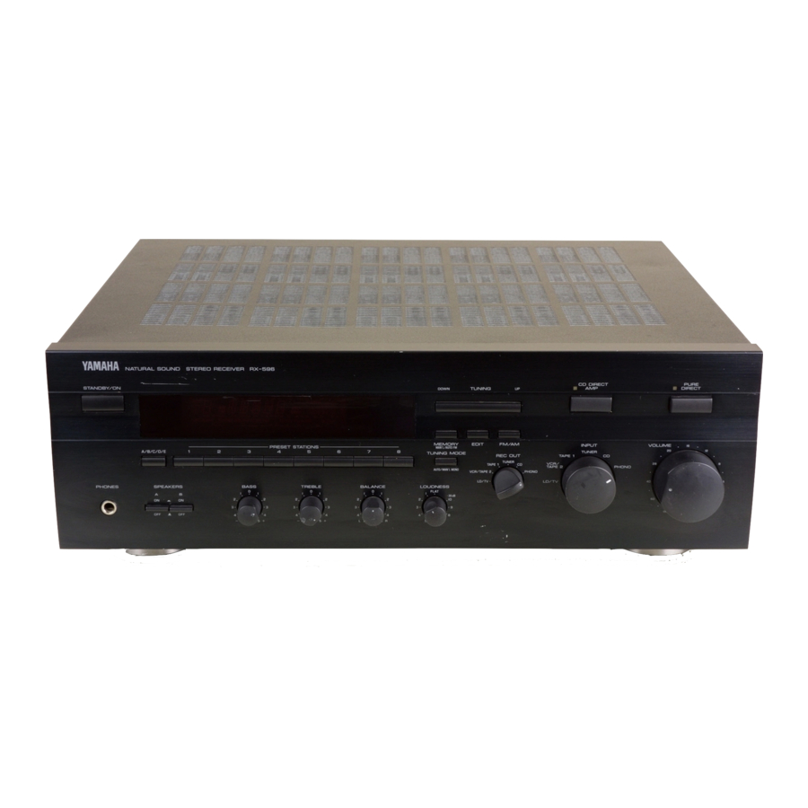
Page 11: Front Panel
FRONT PANEL STANDBY/ON switch TUNING DOWN/UP button Press this switch to turn on the power to this unit, Press Used for tuning. Press the "UP" side to tune in to higher again to turn this unit into the standby mode, frequencies, and press the 'DOWN"... - Page 12 PHONES jack BALANCE control When you listen with headphones, connect the headphones Adjusts the balance of the output volume to the left and right the PHONES jack. speakers to compensate for sound imbalance caused When listening with headphones privately, set both the speaker location or listening...
- Page 13 DISPLAY PANEL Multi4nformation display @MEMORY indicator Displays various information, for example station frequency, When the MEMORY button is pressed, this indicator flashes preset station number and name of selected input source. for about 5 seconds. While this indicator is flashing, displayed station can be programmed...
-
Page 14: Remote Control
If the CD player and tape deck connected to this unit are YAMAHA components designed for remote control compatibility, this remote control transmitter... - Page 15 From page 13 to 19, this manual describes how to operate this unit mainly by using the front panel control parts. To operate this unit on the remote control transmitter, use the corresponding keys on the remote control transmitter. TO PLAY A SOURCE Select the speakers to be used.
- Page 16 TO RECORD A SOURCE TO TAPE (OR MD) y_H_ ........13,5 Begin recording on the tape deck (or MD recorder etc.) Select the source you want to record, or VCR connected to this unit, I_NER TAr_ I. • To monitor the sound (and/or picture)
- Page 17 Adjust the balance of the output volume to the left and right Because one or two speaker systems can be connected to this speakers to compensate for sound imbalance caused from unit, the SPEAKERS switches allow you to select speaker speaker location or listening...
- Page 18 Normally, if station signals are strong and there is no interference, quick automatic-search tuning (AUTOMATIC TUNING) possible. However, if signals of the station you want to select are weak, you must tune to it manually (MANUAL TUNING). Y_H_ ....... AUTOMATIC TUNING MANUAL TUNING...
-
Page 19: Preset Tuning
MANUAL PRESET TUNING This unit can store station frequencies selected by tuning operation. With this function, you can recall any desired station only by selecting the preset station number where it is stored. Up to 40 stations (8 stations x 5 groups) can be stored. - Page 20 AUTOMATIC PRESET TUNING You can make use of an automatic preset tuning function for FM stations. With this function, this unit performs automatic tuning stores FM stations with strong signals sequentially. Up to 40 stations are stored automatically in the same way as in the manual preset tuning method...
-
Page 21: Exchanging Preset Stations
EXCHANGING PRESET STATIONS You can exchange the places of two preset stations with each other as shown below, 2, 4 Y_MAH_ ......Example) If you want to shift the preset station on E1 to A5, and vice versa, Recall the preset station on E1 (by following the method... - Page 22 SYMPTOM column, disconnect the power cord and contact your authorized YAMAHA dealer or service center for help. SYMPTOM CAUSE REMEDY The unit fails to turn on when the STANDBY/ON...
-
Page 23: Audio Section
AUDIO SECTION Tone Control Characteristics Selectivity ..........32 dB BASS: Boost/cut ...._+10dB (20 Hz) Minimum RMS Output Power per Channel Turnover Frequency ... 350 Hz Signal-to-Noise Ratio ......50 dB 8 ohms, 20 Hzto 20 kHz, 0025% THD TREBLE: Boost/cut ..... -
Page 24: Pure Direct
Nous vous rememions d'avoir porte votre choix sur ce r6cepteur ster6o YAMAHA. @ Puissance de sortie RMS de 80W + 80W @ Interrupteur PURE DIRECT pour _a reproduction _a p_us fid_e du son (8 ohms), distorsion harmonique totale d'origine 0,025%, 20-20.000... - Page 25 Apres le deballage, verifier que les pieces suivantes sont incluses, Antenne FM interieure Emetteur de tel6commande Piles (tai!le AA, R6, UM-3) Cadre=antenne Adaptateur d'antenne (Modeles pour les Etats=Unis et le Canada seulement) Pour garantir les meilleures performances possible, lire ce Toujours regler la commande...
- Page 26 mMPORTANT POUR LES CONSOMMATEURS CANADIENS Noter le numero de serie de votre appareil dans I'espace dessous. POUR EVITER LES CHOCS ELECTRIQUES, INTRODUIRE LA LAME LA PLUS LARGE DE LA FICHE DANS LA BORNE Modele CORRESPONDANTE DE LA PRISE ET POUSSER JUSQU'AU FOND.
- Page 27 "R", entre '+" et "+" et entre '-" et "-", Voir aussi le mode d'emploi de chaque appareil branche & cet appareil. * S'il y a des composants YAMAHA numerot6s etc. sur le panneau arriere, il est possible d'effectuer facilement raccordements en raccordant...
- Page 28 RACCORDEMENT DES ENCEtNTES Raccorder les bornes SPEAKERS aux enceintes avec des Remarques cables de section adequate et aussi courts que possible. Si les ® Une ou deux paires d'enceintes peuvent 6tre branchees & branchements sont mal faits, aucun son ne sera entendu cet apparei!.
- Page 29 RACCORDEMENTS DES ANTENNES ® Raccorder chaque antenne correctement aux bornes design6es, se!on les schemas ci-dessous. ® Les deux antennes AM et FM interieures sont fournies avec cet appareil. En gen6ral, ces antennes sont d'une sensibilite adequate. Cependant, une antenne exterieure installee correctement donnera...
- Page 30 PANNEAU AVANT puma DmeCT VOLUME • • PHONES [nterrupteur d'attente/marche (STANDBY/ON) Touche de syntonisation bas/haut (TUNING DOWN/UP) Le presser pour mettre cet apparei! en marche. Le presser & Ella permet de syntoniser les stations. Appuyer sur le c6te nouveau pour mettre cet appareil en mode d'attente, "UP"...
- Page 31 Prise de casque d'_coute (PHONES) Commande de I'&quilibre sonore (BALANCE) Pour effectuer une ecoute au casque, brancher le casque Regle I'equilibre des sons entre les enceintes gauche et droite d'ecoute a la prise pour casque (PHONES). Pour obtenir pour compenser tout d6sequilibre provoque par un...
- Page 32 PANNEAU D'AFFICHAGE AMI--_ /--/ /--/ /T Affichage multi4nformations Indicateur de m6moire (MEMORY) II affiche diverses informations, par exemple la frequence Quand la touche MEMORY est pressee, cet indicateur clignote station, le numero de station prer6gl6e et le nom de la source pendant environ 5 secondes.
- Page 33 Si le lecteur de disque compact et la platine a cassette raccordes a cet apparel! sont des appareils YAMAHA compatibles avec le fonctionnement tel6commande, alors il sera aussi possible de commander les diverses fonctions...
- Page 34 De la page 32 a la page 38, ce mode d'emploi decrit principalement la maniere de faire fonctionner cet appareil au moyen commandes du panneau avant. Pour faire fonctionner cet appareil au moyen de la t6iecommande, utiliser les touches de la tel6commande portant le m_me...
- Page 35 ENREGISTREMENT D'UNE SOURCE SUR UNE BANDE MAGNETIQUE (OU UN MINIDJSQUE) y_t_H_ ....... 13,5 Enclencher I'enregistrement sur la platine a cassette Selectionner la source que I'on veut enregistrer. (ou magnetophone & minidisque, etc,) ou sur le magnetoscope raccorde a cet appareil, _NER TAr_ I.
- Page 36 Une ou deux paires d'enceintes peuvent 6tre branchees a cet appareik Les commutateurs d'enceintes SPEAKERS Regler I'equilibre des sons entre les enceintes gauche permettent de faire la selection de la paire A ou B choisie, droite pour compenser tout des6quilibre provoque par un des deux...
- Page 37 Lorsque les signaux des stations sont forts et qu'il n'y apas d'interferences, la syntonisation rapide avec recherche automatique (SYNTONISATION AUTOMATIQUE) est possible. Cependant, si les signaux de la station desirGe sont faibles, il faudra avoir recours & une syntonisaton manuelle (SYNTONISATION MANUELLE).
- Page 38 SYNTON!SATION PREREGLEE MANUELLE Cet appareil peut memoriser la frequence des stations d'emission selectionn6e par syntonisation. Grace a cette fonction, il suffit de selectionner le numero de station prer6gl6e sur lequel elle est memoris6e pour rappeler la station correspondante. II est possible memoriser jusqu'a 40 stations...
- Page 39 SYNTONtSATION PREREGLEE AUTOMATIQUE I! est aussi possible d'utiliser la fonction de syntonisation prer6gl6e automatique pour les stations FM seulement. Grace a cette fonction, I'appareil peut effectuer la syntonisation automatique et la memorisation ordonnee des stations FM emettant des signaux puissants. Jusqu'a 40 stations peuvent...
- Page 40 PERMUTATION DE STATIONS PREREGLEES II est possible de permuter les touches de memorisation de deux stations prer6gl6es de la maniere indiquee ci°dessous, 2, 4 y_MAHA ......Exemple: Pour permuter la station prer6gl6e de E1 a A5, et vice-versa. Rappeler la station prer6gl6e sur E1 (en suivant methode...
- Page 41 Si vous avez queique doute ou question, consulter votre revendeur officie! YAMAHA le plus proche, SYMPTOME CAUSE REMEDE L'appareil ne ee met pae seas tension Iorequ'on Le cordon d alimentation n'est pas branche oune Bien brancher le cordon d alimentation.
- Page 42 SECTION AUDIO SECTION AiV] Separation des canaux CD/TAPE 1/VCR.TAPE 2/LD.TV Puissance de sortie minimum RMS par canal Gamme de syntonisation (entree terminee 5,1 k-ohms, 1 kHz) 8 ohms, 20 Hz _ 20 kHz, 0,025% de DHT [Modeles pour tes Etats-Unis, le Canada et ............
- Page 43 BEI HAMBURG F R OF GERMANY YAMAHA ELECTRON_QUE FRANCE RU _ AMBRO_SE CROIZAT BF'70 CROISSY BEAUBOURG 77312 MARNE /A VALL_F CFD_X02 FRANCE YAMAHA CORPORATION YAMAHA ELECTRONICS (UK} LTD YAMAHA HOUSE¸ RICKMANSWORFH ROAD WATFORD HFRFS ENGLAND YAMAHA 8CANDINAVEA J A WETTERGRENS...
Need help?
Do you have a question about the RX-596 and is the answer not in the manual?
Questions and answers