Table of Contents
Advertisement
Quick Links
Advertisement
Table of Contents

Related Manuals for Yamaha HTR-6090


Summary of Contents for Yamaha HTR-6090
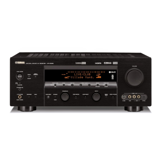
- Page 1 HTR-6090 AV Receiver OWNER’S MANUAL...
-
Page 2: Important Safety Instructions
IMPORTANT SAFETY INSTRUCTIONS IMPORTANT SAFETY INSTRUCTIONS CAUTION RISK OF ELECTRIC SHOCK DO NOT OPEN CAUTION: TO REDUCE THE RISK OF ELECTRIC SHOCK, DO NOT REMOVE COVER (OR BACK). NO USER-SERVICEABLE PARTS INSIDE. REFER SERVICING TO QUALIFIED SERVICE PERSONNEL. • Explanation of Graphical Symbols The lightning flash with arrowhead symbol, within an equilateral triangle, is intended to alert you to the presence of uninsulated “dangerous voltage”... - Page 3 This product, when installed as indicated in the instructions contained in this manual, meets FCC requirements. Modifications not expressly approved by Yamaha may void your authority, granted by the FCC, to use the product. 2 IMPORTANT: When connecting this product to accessories and/or another product use only high quality shielded cables.
- Page 4 YAMAHA will not be held responsible for any damage resulting from use of this unit with a voltage other than specified.
-
Page 5: Table Of Contents
Connecting other components ... 21 Connecting a multi-format player or an external decoder ... 25 Connecting a YAMAHA iPod universal dock ... 26 Using the VIDEO AUX jacks on the front panel ... 26 Connecting the FM and AM antennas ... 27 Connecting the power cable... -
Page 6: Features
“iPod” is a trademark of Apple Computer, Inc., registered in the U.S. and other countries. FEATURES iPod controlling capability ◆ DOCK terminal to connect a YAMAHA iPod universal dock (such as the YDS-10, sold separately), which supports iPod (Click and Wheel), iPod nano, and iPod mini Other features ◆... -
Page 7: Getting Started
Supplied accessories Check that you received all of the following parts. Remote control POWER PHONO V-AUX/DOCK TV VOL – TV MUTE LEVEL TITLE A-E/CAT. RETURN XM MEMORY CLASSICAL STEREO DISC SKIP Speaker terminal wrench Indoor FM antenna About this manual •... -
Page 8: Controls And Functions
CONTROLS AND FUNCTIONS CONTROLS AND FUNCTIONS Front panel This section describes only the amplifier controls and functions of this unit. See the following pages for details about other control and functions. • AM/FM tuning ... see page 53 • XM satellite radio tuning ... see page 61 MAIN ZONE ZONE 2 ZONE 2... - Page 9 PHONES jack Outputs audio signals for private listening with headphones (see page 40). 0 ENHANCER Turns on or off the Compressed Music Enhancer mode (see page 51). A NIGHT Turns on or off the night listening modes (see page 52). B PURE DIRECT Turns on or off the Pure Direct mode (see page 49).
-
Page 10: Remote Control
CONTROLS AND FUNCTIONS Remote control ■ Remote control controls and functions This section describes only the amplifier controls and functions of this unit. See the following pages for details about other control and functions. • AM/FM tuning ... see page 53 •... - Page 11 0 MACRO ON/OFF Turns on or off the macro function (see page 106). A MACRO Programs a series of operations to be controlled with a single button (see page 106). B STANDBY Sets the main zone to the standby mode (see page 30). Note This button is operational only when MASTER ON/OFF on the front panel is pressed inward to the ON position.
-
Page 12: Preparing The Remote Control
CONTROLS AND FUNCTIONS Preparing the remote control ■ Installing batteries in the remote control Press the part and slide the battery compartment cover off. Insert the four supplied batteries (AAA, R03, UM-4) according to the polarity markings on the inside of the battery compartment. Slide the cover back until it snaps into place. -
Page 13: Front Panel Display
HDMI IN 1 or HDMI IN 2 jacks (see page 18). 2 DOCK indicator Lights up when you station your iPod in a YAMAHA iPod universal dock (such as the YDS-10, sold separately) connected to the DOCK terminal of this unit (see page 26). - Page 14 CONTROLS AND FUNCTIONS 0 neural indicator Lights up when the Neural Surround decoder is activated (see page 80). A DSP indicators The respective indicator lights up when any of the DSP sound field programs are selected. CINEMA DSP indicator Lights up when you select a CINEMA DSP sound field program (see page 44).
-
Page 15: Rear Panel
Rear panel COMPONENT VIDEO MONITOR OUT CBL/SAT (PLAY) (REC) TAPE REMOTE HDMI CENTER FRONT(6CH) SURROUND PHONO CD-R IN 2 CBL/ IN (PLAY) OUT(REC) WOOFER SB(8CH) IN 1 AUDIO MULTI CH INPUT DIGITAL INPUT DOCK COAXIAL DVR/ VCR2 1 REMOTE jacks See page 112 for details. -
Page 16: Connections
1.8 m (6 ft) above the floor. Subwoofer (SW) The use of a subwoofer with a built-in amplifier, such as the YAMAHA Active Servo Processing Subwoofer System, is effective not only for reinforcing bass frequencies from any or all channels, but also for high... -
Page 17: Connecting Speakers
Connecting speakers Be sure to connect the left channel (L), right channel (R), “+” (red) and “–” (black) properly. If the connections are faulty, no sound will be heard from the speakers, and if the polarity of the speaker connections is incorrect, the sound will be unnatural and lack bass. -
Page 18: Connecting The Speaker Cable
Connect presence left and right speakers to these terminals. SUBWOOFER jack Connect a subwoofer with a built-in amplifier (such as the YAMAHA Active Servo Processing Subwoofer System) to this jack. ■ Connecting the speaker cable Remove approximately 10 mm (0.4 in) of... - Page 19 Hook the speaker terminal wrench onto the WRENCH HOLDER on the rear panel of this unit when not in use. ■ Connecting the banana plug The banana plug is a single-pole electrical connector widely used to terminate speaker cables. Banana plug Tighten the knob using the supplied speaker terminal wrench.
-
Page 20: Using Bi-Amplification Connections
CONNECTIONS Using bi-amplification connections Some of the speakers have speaker wire connections that allow bi-amplification to enhance the performance of the speaker system. This unit allows you to make bi- amplification connection to one speaker system. Check if your speakers support bi-amplification. As these speakers are shipped to you, you will note shorting bars or bridges, one connecting the two red input terminals and the other connecting the two black input terminals. -
Page 21: Information On Jacks And Cable Plugs
Information on jacks and cable plugs Audio jacks and cable plugs AUDIO DIGITAL COAXIAL (White) (Red) (Orange) Left and right Coaxial analog audio digital audio cable plugs cable plug ■ Audio jacks This unit has three types of audio jacks. Connection depends on the availability of audio jacks on your other components. -
Page 22: Information On Hdmi
CONNECTIONS Information on HDMI This unit has the HDMI IN 1, HDMI IN 2 and HDMI OUT jacks for digital audio and video signal input/output. Connect the HDMI IN 1 or HDMI IN 2 jack of this unit to the HDMI output jack of other HDMI components (such as a DVD player). -
Page 23: Audio And Video Signal Flow
Audio and video signal flow ■ Audio signal flow Input HDMI DIGITAL AUDIO (COAXIAL) DIGITAL AUDIO (OPTICAL) AUDIO Digital output Analog output Notes • 2-channel as well as multi-channel PCM, Dolby Digital and DTS signals input at the HDMI IN 1 or HDMI IN 2 jack can be output at the HDMI OUT jack only when “SUPPORT AUDIO”... -
Page 24: Connecting A Tv Monitor Or Projector
CONNECTIONS Connecting a TV monitor or projector Connect your TV (or projector) to the HDMI OUT jack, the COMPONENT VIDEO MONITOR OUT jacks, the S VIDEO MONITOR OUT jack or the VIDEO MONITOR OUT jack of this unit. CAUTION Do not connect this unit or other components to the AC power supply until all connections between components are complete. -
Page 25: Connecting Other Components
Connecting other components CAUTION Do not connect this unit or other components to the AC power supply until all connections between components are complete. Notes • When “V CONV.” is set to “OFF” (see page 96), be sure to make the same type of video connections as those made for your TV (see page 20). -
Page 26: Connecting A Dvd Recorder, Pvr Or Vcr
CONNECTIONS ■ Connecting a DVD recorder, PVR or VCR Note When you connect another VCR to this unit, connect it to the VCR 1 terminals (S VIDEO IN, VIDEO IN, AUDIO IN, S VIDEO OUT, VIDEO OUT and AUDIO OUT jacks) same as DVR/VCR 2 terminals except the DIGITAL INPUT (COAXIAL) jack. ■... -
Page 27: Connecting Audio Components
■ Connecting audio components Notes • To make a digital connection to a component other than the default component assigned to each the DIGITAL INPUT jack or the DIGITAL OUTPUT jack, select the corresponding setting for “OPTICAL OUT”, “OPTICAL IN”, or “COAXIAL IN” in “I/O ASSIGNMENT”... -
Page 28: Connecting An External Amplifier
CONNECTIONS ■ Connecting an external amplifier This unit has more than enough power for any home use. However, if you want to add more power to the speaker output or if you want to use another amplifier, connect an external amplifier to the PRE OUT jacks. Notes •... -
Page 29: Connecting A Multi-Format Player Or An External Decoder
Connecting a multi-format player or an external decoder This unit is equipped with 6 additional input jacks (left and right FRONT, CENTER, left and right SURROUND and SUBWOOFER) for discrete multi-channel input from a multi-format player, external decoder, sound processor or pre- amplifier. -
Page 30: Connecting A Yamaha Ipod Universal Dock
This unit is equipped with the DOCK terminal on the rear panel that allows you to connect a YAMAHA iPod universal dock (such as the YDS-10, sold separately) where you can station your iPod and control playback of your iPod using the supplied remote control. -
Page 31: Connecting The Fm And Am Antennas
• A properly installed outdoor antenna provides clearer reception than an indoor one. If you experience poor reception quality, install an outdoor antenna. Consult the nearest authorized YAMAHA dealer or service center about outdoor antennas. Indoor FM AM loop antenna... -
Page 32: Connecting The Power Cable
CONNECTIONS Connecting the power cable ■ Connecting the AC power cable CAUTION Use the supplied AC cable. Do not use other AC power cables as doing so may result in fire or electrical shock. Plug the supplied AC power cable into the AC inlet after all other connections are complete, then plug the AC power cable into an AC wall outlet. -
Page 33: Setting The Speaker Impedance
Setting the speaker impedance CAUTION If you are to use 6 ohm speakers, set “SPEAKER IMP.” to “6ΩMIN” as follows BEFORE using this unit. 4 ohm speakers can be also used as the front speakers. MAIN ZONE ZONE 2 ZONE 2 CONTROLS ON/OFF ON/OFF... -
Page 34: Turning On And Off The Power
CONNECTIONS Turning on and off the power When all connections are complete, turn on this unit. MAIN ZONE ON/OFF MAIN ZONE ZONE 2 ZONE 2 CONTROLS ON/OFF ON/OFF PRESET/TUNING FM/AM A/B/C/D/E MASTER SEARCH MODE CATEGORY EDIT OPTIMIZER MIC PROGRAM PHONES ENHANCER NIGHT PURE DIRECT... -
Page 35: Auto Setup
This unit employs the YPAO (YAMAHA Parametric Room Acoustic Optimizer) technology which lets you avoid troublesome listening-based speaker setup and achieves highly accurate sound adjustments automatically. The supplied optimizer microphone collects and this unit analyzes the sound your speakers produce in your actual listening environment. - Page 36 AUTO SETUP Make sure of the following check points before starting the AUTO SETUP operations. • Speakers are connected appropriately. • Supplied optimizer microphone is connected to this unit and placed appropriately. • Headphones are disconnected from this unit. • The room is sufficiently quiet. •...
- Page 37 Volume level LEVEL Checks and adjusts the volume level of each speaker. Choices: CHECK, SKIP • Select “CHECK” to automatically check and adjust this item. • Select “SKIP” to skip this item and perform no adjustments. Press n to select “START” and then press ENTER to start the setup procedure.
- Page 38 AUTO SETUP Press ENTER to display the setup results in detail. PRESET/CH ENTER A-E/CAT. RESULT:EXIT . RESULT 5/4/0.1 DIST: 14.0/ 17.0ft LVL : -9.0/ +6.5dB SET CANCEL [ ]/[ ]:Up/Down [ENTER]:Enter RESULT:WIRING FRONT L;;;;;;;OK [ ]/[ ]:Select [ENTER]:Return Press l / h repeatedly to toggle between the setup result displays.
- Page 39 Press ENTER to return to the top “RESULT:EXIT” display. PRESET/CH RESULT:EXIT . RESULT ENTER DIST: 14.0/ 17.0ft LVL : -9.0/ +6.5dB SET CANCEL A-E/CAT. [ ]/[ ]:Up/Down [ENTER]:Enter Make sure the pointer is pointing at “SET” and “CANCEL” and then press l / h to select “SET”...
- Page 40 AUTO SETUP ■ If “WARNING” appears When this unit detects potential problems during the “AUTO SETUP” procedure, “WARNING” appears in the “RESULT:EXIT” display. Check the warning messages to correct your speaker settings. Note Warnings differ from errors in that warnings do not cancel the “AUTO SETUP”...
-
Page 41: Playback
CAUTION Extreme caution should be exercised when you play back CDs encoded in DTS. If you play back a CD encoded in DTS on a DTS-incompatible CD player, you will only hear some unwanted noise that may damage your speakers. Check whether your CD player supports CDs encoded in DTS. Also, check the sound output level of your CD player before you play back a CD encoded in DTS. - Page 42 PLAYBACK Start playback on the selected source component or select a broadcast station. • Refer to the operating instructions for the source component. • See page 53 for details about tuning instructions. • See page 64 for details about XM Satellite Radio tuning instructions.
-
Page 43: Selecting Audio Input Jacks (Audio Select)
Selecting audio input jacks (AUDIO SELECT) This unit comes with a variety of input jacks. Use this feature (Audio input jack select) to switch the input jack assigned to an input source when more than one jacks are assigned to an input source. •... -
Page 44: Selecting The Multi Ch Input Component
PLAYBACK Selecting the MULTI CH INPUT component Use this feature to select the component connected to the MULTI CH INPUT jacks (see page 25) as the input source. Rotate the input selector on the front panel to select MULTI CH INPUT (or MULTI CH IN on the remote control). -
Page 45: Displaying The Input Source Information
Displaying the input source information You can display the format, sampling frequency, channel, bit rate and flag data of the current input signal. Set the operation mode selector to AMP and then press SET MENU on the remote control. The top “SET MENU” display appears in the OSD. SET MENU SOURCE MENU... -
Page 46: Playing Video Sources In The Background Of An Audio Source
PLAYBACK Playing video sources in the background of an audio source You can combine a video image from a video source with sound from an audio source. For example, you can enjoy listening to classical music while viewing beautiful scenery from the video source on the video monitor. Press the input selector buttons on the remote control to select a video source and then an audio source. -
Page 47: Sound Field Programs
This unit is equipped with a variety of precise digital decoders that allow you to enjoy multi-channel playback from almost any stereo or multi-channel sound source. This unit is also equipped with a YAMAHA digital sound field processing (DSP) chip containing several sound field programs which you can use to enhance your playback experience. -
Page 48: Sound Field Program Descriptions
SOUND FIELD PROGRAMS Sound field program descriptions Select a sound field program based on your listening preference, not merely on the name of the program, etc. Remote control Category of the button program MOVIE MOVIE This program clearly reproduces dialog and sound effects in the latest sound form for science fiction films, thus creating a broad and expansive cinematic space amid silence. -
Page 49: For Various Sources
CLASSICAL CLASSICAL This program creates a relatively wide space with a high ceiling like an audience hall in a palace. It offers pleasant reverberations that are suitable for courtly music and chamber music. DSP LEVEL LIVENESS INIT. DLY REV.TIME LIVE/CLUB LIVE/CLUB A traditional jazz club in New York, located on 7th Avenue. -
Page 50: For Visual Sources Of Music
SOUND FIELD PROGRAMS ENTERTAIN ENTERTAINMENT This sound field has been optimized for action games such as car racing and FPS games. It uses the reflection data that limits the effects range per channel in order to offer a powerful playing environment with a being-there feeling by enhancing various effects tones while maintaining a clear sense of directions. -
Page 51: Stereo Playback
MOVIE MOVIE This program creates the extremely wide sound field of a 70-mm movie theater. It precisely reproduces the source sound in detail, making both the video and the sound field incredibly real. This is ideal for any kind of video source encoded with Dolby Surround, Dolby Digital or DTS (especially large-scale movie productions). -
Page 52: Enjoying Unprocessed Input Sources
SOUND FIELD PROGRAMS ■ Using sound field programs without surround speakers (Virtual CINEMA DSP) Virtual CINEMA DSP allows you to enjoy the CINEMA DSP programs without surround speakers. It creates virtual speakers to reproduce the natural sound field. When you set “SUR. L/R SP” NONE”... -
Page 53: Using Audio Features
Enjoying pure hi-fi sound Use the Pure Direct mode to enjoy the pure high fidelity sound of the selected source. When the Pure Direct mode is activated, this unit plays back the selected source with the least circuitry. Press PURE DIRECT on the front panel (or on the remote control) to turn on or off the Pure Direct mode. -
Page 54: Adjusting The Speaker Level
USING AUDIO FEATURES Adjusting the speaker level You can adjust the output level of each speaker while listening to a music source. This is also possible when playing sources input at the MULTI CH INPUT jacks. Note This operation will override the level adjustments made in “AUTO SETUP”... -
Page 55: Selecting The Compressed Music Enhancer Mode
Selecting the Compressed Music Enhancer mode Compression artifacts (such as the MP3 format) are created by a lossy compression scheme where the audio is resampled to lower the bit rate and to remove sounds that are indistinguishable to typical human hearing. The Compressed Music Enhancer feature of this unit enhances your listening experience by regenerating the missing harmonics in a compression artifact. -
Page 56: Selecting The Night Listening Mode
USING AUDIO FEATURES Selecting the night listening mode The night listening modes are designed to improve listenability at lower volumes or at night. Choose either “NIGHT:CINEMA” or “NIGHT:MUSIC” depending on the type of material you are playing. Press NIGHT on the front panel (or set the operation mode selector to AMP and then press NIGHT on the remote control) repeatedly to select “NIGHT:CINEMA”... -
Page 57: Fm/Am Tuning
There are 2 tuning methods: automatic and manual. Automatic tuning is effective when station signals are strong and there is no interference. If the signal from the station you want to select is weak, tune into it manually. You can also use the automatic and manual preset tuning features to store up to 40 stations (A1 to E8: 8 preset station numbers in each of the 5 preset station groups). -
Page 58: Automatic Tuning
FM/AM TUNING Automatic tuning Automatic tuning is effective when station signals are strong and there is no interference. MAIN ZONE ZONE 2 ZONE 2 CONTROLS ON/OFF ON/OFF PRESET/TUNING FM/AM A/B/C/D/E PRESET/TUNING/CH MEMORY MASTER SEARCH MODE CATEGORY EDIT MAN'L/AUTO FM OPTIMIZER MIC PROGRAM INPUT PHONES... -
Page 59: Manual Tuning
Manual tuning If the signal received from the station you want to select is weak, tune into it manually. Note Manually tuning into an FM station automatically switches the tuner to monaural reception to increase the signal quality. MAIN ZONE ZONE 2 ZONE 2 CONTROLS... -
Page 60: Automatic Preset Tuning
FM/AM TUNING Automatic preset tuning You can use the automatic preset tuning feature to store up to 40 FM stations with strong signals (A1 to E8: 8 preset station numbers in each of the 5 preset station groups) in order. You can then recall any preset station easily by selecting the preset station number. -
Page 61: Manual Preset Tuning
Manual preset tuning You can also store up to 40 stations (A1 to E8: 8 preset station numbers in each of the 5 preset station groups) manually. MAIN ZONE ZONE 2 ZONE 2 CONTROLS ON/OFF ON/OFF PRESET/TUNING FM/AM A/B/C/D/E PRESET/TUNING/CH MEMORY MASTER SEARCH MODE... -
Page 62: Selecting Preset Stations
FM/AM TUNING Selecting preset stations You can tune into any desired station simply by selecting the preset station group and number under which it was stored. MAIN ZONE ZONE 2 ZONE 2 CONTROLS ON/OFF ON/OFF PRESET/TUNING FM/AM A/B/C/D/E PRESET/TUNING/CH MASTER SEARCH MODE CATEGORY EDIT... -
Page 63: Exchanging Preset Stations
Exchanging preset stations You can exchange the assignments of two preset stations with each other. The example below describes the procedure to exchange preset station “E1” with “A5”. MAIN ZONE ZONE 2 ZONE 2 CONTROLS ON/OFF ON/OFF PRESET/TUNING FM/AM A/B/C/D/E PRESET/TUNING/CH MEMORY MASTER... -
Page 64: Xm Satellite Radio Tuning
XM SATELLITE RADIO TUNING XM SATELLITE RADIO TUNING XM Satellite Radio is a satellite radio service with millions of listeners across the United States and Canada, broadcasting live daily. The XM Satellite Radio channel lineup includes over 160 digital channels of choice from coast to coast: 67 commercial-free music channels, featuring hip hop to opera, classical to country, bluegrass to blues;... -
Page 65: Xm Satellite Radio Controls And Functions
XM Satellite Radio controls and functions Note The following controls are available only when “XM” is selected as the input source. Rotate the INPUT selector on the front panel (or set the operation mode selector to SOURCE and then press XM on the remote control) to select “XM” as the input source. ■... -
Page 66: Activating Xm Satellite Radio
XM SATELLITE RADIO TUNING 6 SRCH MODE Changes the search mode between the All Channel Search, Category Search, and Preset Search modes (see page 65). 7 A-E/CAT. l / h (All Channel Search mode) Changes the channel category. (Category Search mode) Changes the channel category. - Page 67 MAIN ZONE ZONE 2 ZONE 2 CONTROLS ON/OFF ON/OFF PRESET/TUNING FM/AM A/B/C/D/E PRESET/TUNING/CH MEMORY MASTER SEARCH MODE CATEGORY EDIT MAN'L/AUTO FM OPTIMIZER MIC PROGRAM INPUT NIGHT PHONES ENHANCER PURE DIRECT STRAIGHT TONE CONTROL AUDIO SELECT SILENT CINEMA EFFECT TV VOL POWER POWER STANDBY...
-
Page 68: Basic Xm Satellite Radio Operations
XM SATELLITE RADIO TUNING Basic XM Satellite Radio operations MAIN ZONE ZONE 2 ZONE 2 CONTROLS ON/OFF ON/OFF PRESET/TUNING FM/AM A/B/C/D/E PRESET/TUNING/CH MASTER SEARCH MODE CATEGORY EDIT MAN'L/AUTO FM OPTIMIZER MIC PROGRAM INPUT PHONES ENHANCER NIGHT PURE DIRECT STRAIGHT TONE CONTROL AUDIO SELECT SILENT CINEMA EFFECT... -
Page 69: All Channel Search Mode
■ All Channel Search mode MAIN ZONE ZONE 2 ZONE 2 CONTROLS ON/OFF ON/OFF PRESET/TUNING FM/AM A/B/C/D/E PRESET/TUNING/CH MEMORY MASTER SEARCH MODE CATEGORY EDIT MAN'L/AUTO FM OPTIMIZER MIC PROGRAM INPUT PHONES ENHANCER NIGHT PURE DIRECT STRAIGHT TONE CONTROL AUDIO SELECT SILENT CINEMA EFFECT TV MUTE... -
Page 70: Category Search Mode
XM SATELLITE RADIO TUNING ■ Category Search mode MAIN ZONE ZONE 2 ZONE 2 CONTROLS ON/OFF ON/OFF PRESET/TUNING FM/AM A/B/C/D/E PRESET/TUNING/CH MASTER SEARCH MODE CATEGORY EDIT MAN'L/AUTO FM OPTIMIZER MIC PROGRAM INPUT PHONES ENHANCER NIGHT PURE DIRECT STRAIGHT TONE CONTROL AUDIO SELECT SILENT CINEMA EFFECT... -
Page 71: Preset Search Mode
■ Preset Search mode Prior to selecting a preset channel in the Preset Search mode, you must preset XM Satellite Radio channels. For details, see “Setting the XM Satellite Radio preset channels” on page 69. The initial factory setting of all preset channels (A1 to E8) is “[001] Preview”. -
Page 72: Direct Number Access Mode
XM SATELLITE RADIO TUNING ■ Direct Number Access mode PRESET/CH LEVEL SET MENU PURE DIRECT TITLE MENU SRCH MODE ENTER AUDIO A-E/CAT. PARAMETER STRAIGHT RETURN DISPLAY XM MEMORY EFFECT CLASSICAL LIVE/CLUB ENTERTAIN MOVIE STEREO SUR. DECODE SELECT EXTD SUR. NIGHT ENHANCER Press SRCH MODE on the remote control repeatedly to select “ALL CH SEARCH”... -
Page 73: Setting The Xm Satellite Radio Preset Channels
Setting the XM Satellite Radio preset channels You can use this feature to store up to 40 XM Satellite Radio channels (A1 to E8: 8 preset channel numbers in each of the 5 preset channel groups). You can then recall any preset channel easily by selecting the preset channel group and number as described in “Preset Search mode”... -
Page 74: Displaying The Xm Satellite Radio Information
XM SATELLITE RADIO TUNING Press PRESET/TUNING/CH l / h on the front panel (or PRESET/CH k / n on the remote control) repeatedly to select a preset channel number (1 to 8) while the MEMORY indicator is flashing. The preset channel number appears in the front panel display. - Page 75 When the channel number / name is displayed: [043] XMU When the channel category is displayed: <CAT>Rock When the artist name / song title is displayed: Coldplay / Spe • The front panel display can indicate up to 14 alphanumeric characters at once.
-
Page 76: Using Ipod
AUDIO OUT (REC) jacks for recording. • Your iPod battery is automatically charged when your iPod is stationed in a YAMAHA iPod universal dock (such as the YDS-10, sold separately) connected to the DOCK terminal of this unit as long as this unit is turned on. You can also select whether this unit charges the battery of the stationed iPod or not when this unit is in the standby mode by selecting the “STANDBY CHRG”... - Page 77 Set the operation mode selector to SOURCE and then press DISPLAY on the remote control. The following display appears in the OSD. PARAMETER SOURCE DISPLAY iPod Playlists Artists Albums Songs Genres Composers Settings Press k / n / l / h on the remote control to navigate the iPod menu and then press ENTER to begin playback of the selected song.
-
Page 78: Recording
RECORDING Recording adjustments and other operations are performed from the recording components. Refer to the operating instructions for those components. CAUTION The DTS signal is a digital bitstream. Attempting to digitally record the DTS bitstream will result in noise being recorded. Therefore, if you want to use this unit to record sources encoded in DTS, the following considerations and adjustments need to be made. -
Page 79: Advanced Sound Configurations
ADVANCED SOUND CONFIGURATIONS Changing sound field parameter settings You can enjoy good quality sound with the initial factory settings. Although you do not have to change the initial factory settings, you can change some of the parameters to better suit the input source or your listening room. Note You cannot change the sound field parameter values when “MEMORY GUARD”... -
Page 80: Sound Field Parameter Descriptions
ADVANCED SOUND CONFIGURATIONS ■ Sound field parameter descriptions You can adjust the values of certain digital sound field parameters so that the sound fields are recreated accurately in your listening room. Not all of the following parameters are found in every program. To change sound field parameter settings to suit your listening environment, see page 75 for details. - Page 81 Sound field parameter ROOM SIZE Room size. Presence, surround, and surround back room size. Adjusts the apparent size of the surround sound field. The larger the value, the larger the surround sound field becomes. As the P.ROOM SIZE sound is repeatedly reflected around a room, the larger the hall is, the longer the time between S.ROOM SIZE the original reflected sound and the subsequent reflections.
- Page 82 ADVANCED SOUND CONFIGURATIONS Sound field parameter REV.TIME Reverberation time. Adjusts the amount of time taken for the dense, subsequent reverberation sound to decay by 60 dB at 1 kHz. This changes the apparent size of the acoustic environment over an extremely wide range. Set a longer reverberation time for “dead” sources and listening room environments, and a shorter time for “live”...
-
Page 83: Selecting Decoders
Sound field parameter DIALG.LIFT Dialog lift. Adjusts the height of the front and center channel sounds by assigning some of the front and center channel elements to the presence speakers. The larger the parameter, the higher the position of the front and center channel sound. Choices: 0, 1, 2, 3, 4, 5 2ch Stereo 2-channel stereo direct. -
Page 84: Decoder Descriptions
ADVANCED SOUND CONFIGURATIONS ■ Decoder descriptions Remote control Category of the button program SUR.DECODE SURROUND DECODE Dolby Pro Logic IIx (or Dolby Pro Logic II) processing for music sources. available when “SB L/R SP” is set to “NONE” (see page 88). PANORAMA DIMENSION Available sound field parameters (see page 76) - Page 85 Decoder parameter descriptions Decoder parameter PRO LOGIC IIx Music Pro Logic IIx Music and Pro Logic II Music panorama. Sends stereo signals to the surround speakers as well as the front speakers for a wraparound effect. PRO LOGIC II Music PANORAMA Choices: OFF, ON PRO LOGIC IIx Music...
- Page 86 ADVANCED SOUND CONFIGURATIONS ■ Selecting decoders for multi-channel sources If you connected surround back speakers, use this feature to enjoy 6.1/7.1-channel playback for multi-channel sources using the Dolby Pro Logic IIx, Dolby Digital EX or DTS-ES decoders. Set the operation mode selector to AMP and then press EXTD SUR.
-
Page 87: Customizing This Unit (Manual Setup)
CUSTOMIZING THIS UNIT (MANUAL SETUP) You can use the following parameters in “SET MENU” to adjust a variety of system settings and customize the way this unit operates. Change the initial settings (indicated in bold under each parameter) to reflect the needs of your listening environment. - Page 88 CUSTOMIZING THIS UNIT (MANUAL SETUP) Input menu 3 INPUT MENU Use this menu to manually reassign the input/output jacks, select the input mode or rename the input source. Parameter A)I/O ASSIGNMENT Assigns the input/output jacks of this unit according to the component to be used. B)INPUT RENAME Changes the name of the input source.
-
Page 89: Using Set Menu
Using SET MENU Use the remote control to access and adjust each parameter. SOURCE TV VOL VOLUME – – – TV MUTE TV INPUT MUTE PRESET/CH LEVEL SET MENU PURE DIRECT TITLE MENU SRCH MODE ENTER AUDIO A-E/CAT. PARAMETER STRAIGHT RETURN DISPLAY EFFECT... -
Page 90: Basic Menu
CUSTOMIZING THIS UNIT (MANUAL SETUP) Press k / n repeatedly and then press ENTER to select and enter the desired submenu. The following display is an example where “LFE LEVEL” is selected. PRESET/CH ENTER A-E/CAT. A-E/CAT. B)LFE LEVEL . SPEAKER;;;;;;0dB HEADPHONE;;;;0dB [ ]/[ ]:Up/Down [ ]/[ ]:Adjust... - Page 91 Front speakers FRONT SP Choices: SMALL, LARGE FRONT SP SMALL LARGE • Select “SMALL” (small) if you have small front speakers that do not reproduce low-frequency signals effectively. The low-frequency signals of the front left and right channels are directed to the speakers selected in “LFE/BASS OUT”...
- Page 92 CUSTOMIZING THIS UNIT (MANUAL SETUP) Surround back speakers SB L/R SP Choices: NONE, SMLx1, SMLx2, LRGx1, LRGx2 SB L/R SP SMLx1 SMLx2 • Select “NONE” (none) if you did not connect surround back speakers. The surround back channel signals are directed to the surround left and right speakers.
- Page 93 ■ Speaker level B)SP LEVEL Use this feature to manually balance the speaker levels between the front left or surround left speakers and each speaker selected in “SPEAKER SET” (see page 86). Control range: –10.0 to +10.0 dB Control step: 0.5 dB Initial setting: FR.
-
Page 94: Sound Menu
CUSTOMIZING THIS UNIT (MANUAL SETUP) Notes • “CENTER”, “SUR. L”, “SUR. R”, “SB L”, “SB R”, “SWFR”, “PRNS L” and “PRNS R” cannot be adjusted if “CENTER SP” (see page 87), “SUR. L/R SP” (see page 87), “SB L/R SP” (see page 88), “LFE/BASS OUT”... - Page 95 Graphic equalizer Use to match the tonal quality of the center, surround L/R and surround back L/R, surround back, presence L/R speakers and the subwoofer with that of the front L/R speakers. You can adjust 7 frequency bands (63Hz, 160Hz, 400Hz, 1kHz, 2.5kHz, 6.3kHz, 16kHz). Choices: –6.0 to +6.0 dB Control step: 0.5 dB A)EQUALIZER...
- Page 96 HDMI OUT jack on the rear panel of this unit. Choices: HTR-6090, OTHER • Select “HTR-6090” to play back HDMI audio signals on this unit. The HDMI audio signals input at the HDMI IN jacks of this unit are not output to the HDMI component connected to the HDMI OUT jack on the rear panel of this unit.
-
Page 97: Input Menu
3 INPUT MENU Use this menu to reassign the input/output jacks, select the input mode or rename the input source. 3 INPUT MENU 1/2 3 INPUT MENU 2/2 . A)I/O ASSIGNMENT . E)MULTI CH SET B)INPUT RENAME C)VOLUME TRIM D)DECODER MODE [ ]/[ ]:Up/Down [ ]/[ ]:Up/Down [ENTER]:Enter... - Page 98 CUSTOMIZING THIS UNIT (MANUAL SETUP) For OPTICAL OUTPUT jacks 8 and 9 OPTICAL Choices: (8) MD/TAPE, CD-R, CD, PHONO, DVD, DTV, CBL/SAT, VCR 1, DVR/VCR 2, V- (9) MD/TAPE, CD-R, CD, PHONO, DVD, DTV, CBL/SAT, VCR 1, DVR/VCR 2, V- OPTICAL OUT .
-
Page 99: Multi Channel Input Setup
■ Volume Trim C)VOLUME TRIM Use this feature to adjust the level of the signal input at each jack. This is useful if you want to balance the level of each input source to avoid sudden changes in volume when switching between input sources. Choices: XM, TUNER, PHONO, CD, CD-R, MD/TAPE, DVD, DTV, CBL/SAT, VCR 1, DVR/VCR 2, V- AUX, DOCK... -
Page 100: Option Menu
CUSTOMIZING THIS UNIT (MANUAL SETUP) 4 OPTION MENU Use this menu to adjust the optional system parameters. 4 OPTION MENU 1/2 . A)DISPLAY SET . E)PARAM. INI B)MEMORY GUARD C)AUDIO SELECT D)DECODER MODE [ ]/[ ]:Up/Down [ENTER]:Enter ■ Display settings A)DISPLAY SET Note Use the “V-RESET”... - Page 101 Component interlace/progressive up-conversion CMPNT I/P Use this feature to activate or deactivate the analog interlace/progressive conversion of the analog video signals input at the composite video, S-video and component video jacks so that the analog video signals deinterlaced from 480i (NTSC)/576i (PAL) to 480p/576p are output at the COMPONENT MONITOR OUT jacks.
- Page 102 CUSTOMIZING THIS UNIT (MANUAL SETUP) ■ Memory guard B)MEMORY GUARD Use this feature to prevent accidental changes to DSP program parameter values and other system settings. Choices: OFF, ON B)MEMORY GUARD [ ]/[ ]:Adjust • Select “OFF” to turn off the “MEMORY GUARD” feature.
- Page 103 ■ Zone set F)ZONE SET F)ZONE SET . ZONE2 VOL;;;;VAR ZONE2 AMP;;;;EXT [ ]/[ ]:Up/Down [ ]/[ ]:Adjust Zone 2 volume ZONE2 VOL Use to select how the volume control will operate with regard to the ZONE 2 OUTPUT jacks. Choices: VAR, FIX •...
-
Page 104: Remote Control Features
REMOTE CONTROL FEATURES In addition to controlling this unit, the remote control can also operate other audiovisual components made by YAMAHA and other manufacturers. To control your TV or other components, you must set up the appropriate remote control code for each input source (see page 102). -
Page 105: Controlling Other Components
■ Controlling other components Set the operation mode selector to SOURCE to control other components selected with the input selector buttons or . You must set the appropriate remote control code for each input source in advance (see page 102). The following table shows the function of each control button used to control other components assigned to each input selector button or... -
Page 106: Setting Remote Control Codes
Note You may not be able to operate your YAMAHA component even if a YAMAHA remote control code is preset as listed above. In this case, try setting another YAMAHA remote control code. Set the operation mode selector to SOURCE and then press an input selector button or to select the input area you want to set up. - Page 107 • The supplied remote control does not contain all possible codes for commercially available audio and video components (including YAMAHA components). If operation is not possible with any of the remote control codes, program the new remote control function using the learn feature (see “Programming codes from other remote controls”...
-
Page 108: Programming Codes From Other Remote Controls
REMOTE CONTROL FEATURES Programming codes from other remote controls You can program remote control codes from other remote controls. Use the learn feature if you want to program functions not included in the basic operations covered by the remote control codes, or an appropriate remote control code is not available. -
Page 109: Changing Source Names In The Display Window
Press and hold the button you want to program on the other remote control until “OK” appears in the display window on the remote control. “NG” appears in the display window on the remote control if learning was unsuccessful. In this case, start over from step 4. -
Page 110: Macro Programming Features
REMOTE CONTROL FEATURES Press k / n to select and enter a character. Pressing n changes the character as follows: A to Z, 1 to 9, 0, + (plus), – (hyphen), ; (semicolon), / (slash), and space. Pressing k changes the characters in reverse order. PRESET/CH ENTER A-E/CAT. -
Page 111: Default Macro Functions
DVR/VCR 2 You can turn on some components (including YAMAHA components) connected to this unit by connecting them to the AC OUTLETS on the rear panel of this unit. Power control may not be synchronized with this unit depending on the component. For details, refer to the operating instructions for the connected component. - Page 112 REMOTE CONTROL FEATURES ■ Programming macro operations You can program your own macro and use the macro programming feature to transmit several remote control commands in sequence at the press of a button. Be sure to set up remote control codes or perform learning operations before programming the macro.
-
Page 113: Clearing Configurations
Clearing configurations You can clear all changes made in each function set, such as learned functions, macros, renamed input area names and setup remote control ID. ■ Clearing function sets Set the operation mode selector to AMP or SOURCE and then press CLEAR by using a ballpoint pen or similar object. - Page 114 REMOTE CONTROL FEATURES ■ Clearing a learned function You can clear the function learned for a certain button in each control area. Set the operation mode selector to AMP or SOURCE and then press an input selector button or to select the input area containing the function you want to clear.
- Page 115 ■ Clearing a macro function You can clear the function programmed for a certain macro button. Set the operation mode selector to AMP or SOURCE and then press MACRO using a ballpoint pen or similar object. “MCR ?” appears in the display window on the remote control.
-
Page 116: Using Multi-Zone Configuration
• Since there are many possible ways to connect and use this unit in a multi-room configuration, we recommend that you consult with your nearest authorized YAMAHA dealer or service center for the Zone 2 connections that best meet your requirements. -
Page 117: Controlling Zone 2
■ Using the internal amplifiers of this unit The SP1 speaker terminals of this Receiver should not be connected to a Passive Loudspeaker Selector Box or more than one loudspeaker per channel. Connection to a Passive Loudspeaker Selector Box or multiple speakers per channel could create an abnormally low impedance load resulting in amplifier damage. - Page 118 USING MULTI-ZONE CONFIGURATION Refer to “Selecting the input source of Zone 2”, “Adjusting the volume level of Zone 2”, “Adjusting the balance of the speaker level in Zone 2” or “Adjusting the tonal quality of Zone 2” on page 116 to perform further operations.
- Page 119 ■ Selecting the input source of Zone 2 Press ZONE 2 INPUT to activate the Zone 2 input select mode and then rotate the INPUT selector on the front panel (or set the operation mode selector to AMP and then press one of the input selector buttons on the remote control) to select the input source of the selected zone.
- Page 120 USING MULTI-ZONE CONFIGURATION ■ Adjusting the balance of the speaker level in Zone 2 Press ZONE 2 CONTROLS on the front panel to activate the Zone 2 control mode. ZONE 2 CONTROLS Press TONE CONTROL repeatedly to select “BALANCE” and then rotate PROGRAM on the front panel to adjust the balance of the front left and right speaker level of the selected zone.
-
Page 121: Advanced Setup
This unit has additional menus that are displayed in the front panel display. The advanced setup menu offers additional operations to adjust and customize the way this unit operates. Change the initial settings (indicated in bold under each parameter) to reflect the needs of your listening environment. Notes •... -
Page 122: Speaker Impedance
ADVANCED SETUP ■ Speaker impedance SPEAKER IMP. Use this feature to set the speaker impedance of this unit so that it matches that of your speakers. Choices: 8ΩMIN, 6ΩMIN • Select “8ΩMIN” to set the speaker impedance to 8 Ω . •... -
Page 123: Setting Remote Control Id
“ON SCREEN” and “FL SCROLL” is not initialized (see page 96). Setting remote control ID hen using multiple YAMAHA receivers/amplifiers, you may be able to operate the other components simultaneously with the default code setting. In this case, set one of the alternative codes to operate this unit separately. - Page 124 ADVANCED SETUP Press the numeric buttons to enter the four- digit remote control code for the input area you want to use. CLASSICAL LIVE/CLUB ENTERTAIN STEREO SUR. DECODE SELECT Remote control AMP codes Select one of the following codes to set the remote control AMP code for the input area you want to use.
- Page 125 Press the numeric buttons to enter the four- digit remote control code for the input area you want to use. CLASSICAL LIVE/CLUB ENTERTAIN MOVIE STEREO SUR. DECODE SELECT EXTD SUR. Remote control tuner codes Select one of the following codes to set the remote control tuner code for the input area you want to use.
-
Page 126: Troubleshooting
Play a source whose signals can be reproduced by this unit. Connect HDMI components that support the HDCP copy protection standards. Set “SUPPORT AUDIO” to “HTR-6090” in “MANUAL SETUP”. Remedy page —... - Page 127 Problem No picture. The output and input for the picture are connected to different types of video jacks. Non-standard video signals are input. Short message “SHORT MESSAGE” is set to “OFF”. displays do not “GRAY BACK” is set to “OFF”. appears in the video monitor.
- Page 128 TROUBLESHOOTING Problem No sound is heard “LFE/BASS OUT” in “SET MENU” is from the subwoofer. set to “FRONT” when a Dolby Digital or DTS signal is being played. “LFE/BASS OUT” in “SET MENU” is set to “SWFR” or “FRONT” when a 2- channel source is being played.
- Page 129 Problem “CHECK SP WIRES” Speaker cables are short-circuited. appears in the front panel display. There is noise This unit is too close to the digital or high- interference from frequency equipment. digital or radio frequency equipment. The picture is The video source uses scrambled or disturbed.
-
Page 130: Xm Satellite Radio
TROUBLESHOOTING ■ XM Satellite Radio If an operation takes longer than usual or an error occurs, one of the following messages may appear in the front panel display. In this case, read the cause and follow the corresponding remedies. Status message CHECK ANTENNA The XM Passport and XM Passport Home Dock are not connected to the XM jack of... - Page 131 ■ Remote control Problem The remote control Wrong distance or angle. does not work or function properly. Direct sunlight or lighting (from an inverter type of fluorescent lamp, etc.) is striking the remote control sensor of this unit. The batteries are weak. The operation mode selector is set incorrectly.
- Page 132 Check that the connected HDMI components support the HDCP copy protection standards. Cause Turn off this unit and reconnect the YAMAHA iPod universal dock to the DOCK terminal of this unit. Try resetting your iPod. Only iPod (Click and Wheel), iPod nano, and iPod mini are supported.
- Page 133 • If warning “W-1” appears, corrections are made, but they may not be optimal. • If warning “W-2” or “W-3” appears, no corrections are made. • If error “E-10” occurs repeatedly, please contact a qualified YAMAHA service center. Cause Check the front L/R speaker connections.
-
Page 134: Resetting The System
RESETTING THE SYSTEM Use this feature to reset all the parameters of this unit to the initial factory settings. Notes • This procedure completely resets all the parameters of this unit including the “SET MENU” parameters. However, the advanced setup menu parameters will not be initialized. -
Page 135: Glossary
■ Bi-amplification connection A bi-amplification connection uses two amplifiers for a speaker. One amplifier is connected to the woofer section of a loudspeaker while the other is connected to the combined mid and tweeter section. With this arrangement each amplifier operates over a restricted frequency range. This restricted range presents each amplifier with a much simpler job and each amplifier is less likely to influence the sound in some way. -
Page 136: Dolby Surround
GLOSSARY ■ Dolby Surround Dolby Surround uses a 4-channel analog recording system to reproduce realistic and dynamic sound effects: 2 front left and right channels (stereo), a center channel for dialog (monaural), and a surround channel for special sound effects (monaural). The surround channel reproduces sound within a narrow frequency range. - Page 137 GLOSSARY ■ Sampling frequency and number of quantized bits When digitizing an analog audio signal, the number of times the signal is sampled per second is called the sampling frequency, while the degree of fineness when converting the sound level into a numeric value is called the number of quantized bits.
-
Page 138: Sound Field Program Information
The acoustics in your room could be changed to those of a concert hall, a dance floor, or a room with virtually any size at all. This ability to create sound fields at will is exactly what YAMAHA has done with the digital sound field processor. ■ CINEMA DSP... -
Page 139: Parametric Equalizer Information
PARAMETRIC EQUALIZER INFORMATION This unit employs YAMAHA Parametric Room Acoustic Optimizer (YPAO) technology, together with the Parametric EQ settings (see page 90), to optimize the frequency characteristics of its parametric equalizer to match your listening environment. YPAO uses a combination of the following three parameters (Frequency, Gain and Q factor) to provide highly precise adjustment of the frequency characteristics. -
Page 140: Specifications
– and, most importantly, without affecting your sensitive hearing. Since hearing damage from loud sounds is often undetectable until it is too late, YAMAHA and the Electronic Industries Association’s Consumer Electronics Group recommend you to avoid prolonged exposure from excessive volume levels. -
Page 141: Sound Output In Each Sound Field Program
SOUND OUTPUT IN EACH SOUND FIELD PROGRAM Front left speaker Center speaker Front right speaker Speaker from which sound is being output PL x : OFF : ON, PRIORITY: PRNS PL x : ON, PRIORITY: SB PL x Program 2-channel audio (monaural) CLASSICAL Hall in Munich... - Page 142 Program 2-channel audio (monaural) MOVIE STANDARD (PLII Movie) (PLIIx Movie) (Neo:6 Cinema) MOVIE Spectacle Sci-Fi Adventure Drama Mono Movie STEREO 2ch Stereo Monaural playback STEREO 7ch Stereo APPENDIX-ii Input source 5.1/6.1-channel 2-channel audio (stereo) audio * PRIORITY: PRNS (Dolby Digital) (DTS) PRIORITY: SB 5.1/6.1-channel...
- Page 143 Program 2-channel audio (monaural) SURROUND DECODE PRO LOGIC SURROUND DECODE PLII Movie PLII Music PLII Game Movie/Game Music SURROUND DECODE PLIIx Movie PLIIx Music PLIIx Game Movie/Game Music Input source 5.1/6.1-channel 2-channel audio (stereo) audio * PRO LOGIC Dolby Digital Dolby Digital Movie/Music/Game Dolby Digital...
- Page 144 Program 2-channel audio (monaural) SURROUND DECODE Neo:6 Cinema Neo:6 Music Cinema Music SURROUND DECODE neural sur. STRAIGHT Monaural playback PURE DIRECT Monaural playback APPENDIX-iv Input source 5.1/6.1-channel 2-channel audio (stereo) audio * Cinema/Music Dolby Digital Dolby Digital 5.1/6.1-channel 5.1/6.1-channel audio * Dolby Digital Dolby Digital audio *...
-
Page 145: List Of Remote Control Codes
TECHNICS ARCAM 0184 THORENS AUDIO RESEARCH 0184 THULE AUDIO TON 0184 UNIVERSUM 0184 AUDIOLAB 0184 VICTOR AUDIOMECA 0184 WARDS CAIRN 0184 YAMAHA CD RECORDER 0056 0184, 0206 KENWOOD 0653 0184 MARANTZ 0653 0027 PHILIPS 0653 YAMAHA 2400 0184 0900 DVD PLAYER... -
Page 146: Tape Deck
1281 THORENS 1216 KATHREIN UHER 0558 VENTURER 1417 KREISELMEYER VICTOR 0101 LABGEAR WARDS 0041, 0185 LOGIX YAMAHA 0203, 1203, 1358, LORENZEN 2601 MAGNAVOX 0749, 0751 (TUNER ID1) 2602 MANHATTAN (TUNER ID2) 2603 (XM ID1) 2604 MARANTZ (XM ID2) 2605 MEDIASAT... - Page 147 GRANADA CONTEC 0036, 0207 CRAIG 0207 GRANDIN CROSLEY 0081 GRUNDIG CROWN 0036, 0064, 0207, 0397, 0445 GRUNPY CURTIS MATHES 0057, 0074, 0081, 0087, 0120, HALLMARK 0172, 0181, 0193, HANKOOK 0478, 0729, 1174, HANSEATIC 1374 DAEWOO 0036, 0057, 0064, HANTAREX 0119, 0135, 0181, HARMAN/KARDON 0081 0197, 0205, 0207, 0401, 0478, 0650,...
- Page 148 SONOLOR 0190, 0235 SONTEC 0064 WATSON SONY 0027, 0677, 0861, WAYCON WHITE WESTINGHOUSE 1127, 1532, 1678 SOUNDESIGN 0205, 0207 SOUNDWAVE 0064, 0445 YAMAHA SOWA 0078, 0087, 0119, 0183, 0205 SQUAREVIEW 0198 STANDARD 0036 STARLITE 0207 STERN 0190, 0286 SUPREME 0027...
- Page 149 REPLAYTV 0641, 0643 VILLAIN 0068 WARDS ROADSTAR 0064, 0099, 0267, 0305 RUNCO 0066 WHITE WESTINGHOUSE 0108 0267 XR-1000 0108 YAMAHA 0069 YAMISHI SABA 0068, 0347 YOKAN SALORA 0070 YOKO SAMPO 0064, 0075 ZENITH SAMSUNG 0072, 0267, 0459 SANKY 0066, 0075...
- Page 152 YAMAHA ELECTRONICS (UK) LTD. YAMAHA HOUSE, 200 RICKMANSWORTH ROAD WATFORD, HERTS WD18 7GQ, ENGLAND YAMAHA SCANDINAVIA A.B. J A WETTERGRENS GATA 1, BOX 30053, 400 43 VÄSTRA FRÖLUNDA, SWEDEN YAMAHA MUSIC AUSTRALIA PTY, LTD. 17-33 MARKET ST., SOUTH MELBOURNE, 3205 VIC., AUSTRALIA...