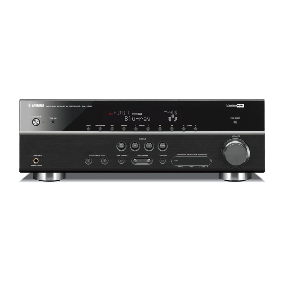
Yamaha RX-V667 Service Manual
Av receiver
Hide thumbs
Also See for RX-V667:
- Owner's manual (144 pages) ,
- Quick reference manual (9 pages) ,
- Owner's manual (114 pages)
Table of Contents
Advertisement
This manual has been provided for the use of authorized YAMAHA Retailers and their service personnel.
It has been assumed that basic service procedures inherent to the industry, and more specifi cally YAMAHA Products, are already known
and understood by the users, and have therefore not been restated.
WARNING:
IMPORTANT:
The data provided is believed to be accurate and applicable to the unit(s) indicated on the cover. The research, engineering, and service
departments of YAMAHA are continually striving to improve YAMAHA products. Modifications are, therefore, inevitable and
specifi cations are subject to change without notice or obligation to retrofi t. Should any discrepancy appear to exist, please contact the
distributor's Service Division.
WARNING:
IMPORTANT:
■ CONTENTS
To Service Personnel ............................................2
Front Panels .........................................................3–4
Rear Panels ...........................................................5–8
Remote Control Panels .......................................9
Specifications ................................................... 10–14
Internal View .......................................................... 15
Service Precautions ............................................ 15
Disassembly Procedures ............................. 16–18
Updating Firmware .......................................... 19–21
Self-Diagnostic Function ...........................22–55
CONFIRMATION OF IDLING CURRENT OF
Amp Unit ...................................................................56
1 0 1 1 7 2
Rx-V667/Htr-6063/
Failure to follow appropriate service and safety procedures when servicing this product may result in personal injury,
destruction of expensive components, and failure of the product to perform as specifi ed. For these reasons, we advise
all YAMAHA product owners that any service required should be performed by an authorized YAMAHA Retailer or
the appointed service representative.
The presentation or sale of this manual to any individual or fi rm does not constitute authorization, certifi cation or
recognition of any applicable technical capabilities, or establish a principle-agent relationship of any form.
Static discharges can destroy expensive components. Discharge any static electricity your body may have
accumulated by grounding yourself to the ground buss in the unit (heavy gauge black wires connect to this buss).
Turn the unit OFF during disassembly and part replacement. Recheck all work before you apply power to the unit.
Copyright © 2010
This manual is copyrighted by YAMAHA and may not be copied or
redistributed either in print or electronically without permission.
AV RECEIVER
RX-A700
SERVICE MANUAL
IMPORTANT NOTICE
Display Data .......................................................57–58
Ic Data ...................................................................59–75
Pin Connection Diagrams ............................. 76–78
Block Diagrams ................................................79–83
Printed Circuit Boards ............................... 84–105
Schematic Diagrams ................................... 107–120
Replacement Parts List ............................ 121–135
Remote Control ........................................... 136–138
Advanced Setup ............................................ 139–144
All rights reserved.
P.O.Box 1, Hamamatsu, Japan
'10.06
Advertisement
Table of Contents

Related Manuals for Yamaha RX-V667


Summary of Contents for Yamaha RX-V667
-
Page 1: Important Notice
This manual has been provided for the use of authorized YAMAHA Retailers and their service personnel. It has been assumed that basic service procedures inherent to the industry, and more specifi cally YAMAHA Products, are already known and understood by the users, and have therefore not been restated. -
Page 2: Rx-V667/Htr
RX-V667/HTR-6063/RX-A700 ■ TO SERVICE PERSONNEL AC LEAKAGE WALL EQUIPMENT TESTER OR 1. Critical Components Information OUTLET UNDER TEST EQUIVALENT Components having special characteristics are marked must be replaced with parts having specifications equal to those originally installed. 2. Leakage Current Measurement (For 120V Models Only) -
Page 3: Front Panels
RX-V667/HTR-6063/RX-A700 ■ FRONT PANELS Top view U model C, R, T, K, A, B, G, F, L models L model Front view RX-V667 (U model) RX-V667 (C, R, T, K, A, B, G, F, L models) - Page 4 RX-V667/HTR-6063/RX-A700 HTR-6063 (C, A models) RX-A700 (U model)
-
Page 5: Rear Panels
RX-V667/HTR-6063/RX-A700 ■ REAR PANELS RX-V667 (U model) RX-V667 (C model) RX-V667 (R model) - Page 6 RX-V667/HTR-6063/RX-A700 RX-V667 (T model) RX-V667 (K model) RX-V667 (A model)
- Page 7 RX-V667/HTR-6063/RX-A700 RX-V667 (B, G, F models) RX-V667 (L model) HTR-6063 (C model)
- Page 8 RX-V667/HTR-6063/RX-A700 HTR-6063 (A model) RX-A700 (U model)
-
Page 9: Remote Control Panels
RX-V667/HTR-6063/RX-A700 ■ REMOTE CONTROL PANELS RAV336 RAV337 RAV338 (U model) (C model) (R, T, K, A, B, G, F, L models) -
Page 10: Specifications
RX-V667/HTR-6063/RX-A700 ■ SPECIFICATIONS ■ Audio Section Signal to Noise Ratio (IHF-A Network) Minimum RMS Output Power (Power Amp. Section) PHONO (MM) (Input shorted) to REC OUT [RX-V667/RX-A700] 5 mV ................ 81 dB or more (20 Hz to 20 kHz, 0.08 % THD, 8 ohms) AV5, etc. - Page 11 HDMI control: OFF / Standby through: OFF ....0.2 W or less HDMI control: ON / Standby through: ON ....2.7 W or less Maximum Power Consumption [R, L models] “SILENT CINEMA” is a trademark of Yamaha Corporation....................590 W Dimensions (W x H x D) ........
- Page 12 RX-V667/HTR-6063/RX-A700 • SELECT MENU Sound field parameters Category Program MOVIE Standard Spectacle Sci-Fi Adventure Drama Mono Movie Sports Action Game Roleplaying Game Music Video MUSIC Hall in Munich Hall in Vienna Chamber Cellar Club The Roxy Theatre The Bottom Line...
- Page 13 RX-V667/HTR-6063/RX-A700 • SET MENU TABLE MAIN VALUE SUB-MENU PARAMETER MENU [INITIAL VALUE] Speaker Auto Measure Optimizes the speaker configuration automatically using YPAO. Setup Manual Power Amp Assign [7ch Normal] / 7ch +1ZONE / 5ch BI-AMP Configuration Front Speaker Large / [Small] When “Subwoofer”...
- Page 14 RX-V667/HTR-6063/RX-A700 MAIN VALUE SUB-MENU PARAMETER MENU [INITIAL VALUE] HDMI HDMI Control [Off] / On Setup ARC (Audio Return Channel) Off / [On] TV Audio Input AV1 / AV2 / AV3 / [AV4] / AV5 / AV6 / AUDIO1 / AUDIO2...
-
Page 15: Internal View
RX-V667/HTR-6063/RX-A700 ■ INTERNAL VIEW VIDEO (2) P.C.B. VIDEO (3) P.C.B. MAIN (3) P.C.B. (R, L models) OPERATION (8) P.C.B. MAIN (2) P.C.B. DIGITAL (3) P.C.B. (RX-A700) VIDEO (1) P.C.B. VIDEO (4) P.C.B. AM/FM TUNER VIDEO (9) P.C.B. (B, G, F models) OPERATION (9) P.C.B. -
Page 16: Disassembly Procedures
RX-V667/HTR-6063/RX-A700 ■ DISASSEMBLY PROCEDURES (Remove parts in the order as numbered.) Disconnect the power cable from the AC outlet. 1. Removal of Top Cover a. Remove 4 screws ( ) and 5 screws ( ). (Fig. 1) b. Lift the rear of the top cover to remove it. - Page 17 RX-V667/HTR-6063/RX-A700 3. Removal of DIGITAL (3) P.C.B. 5. Removal of AMP Unit (RX-A700 model only) a. Remove screw ( ), 2 screws ( ) and 4 screws ( ). (Fig. 2) a. Remove 2 jack screws ( ). (Fig. 3) b.
- Page 18 RX-V667/HTR-6063/RX-A700 When checking the P.C.B.s: • Follow the procedure below to place the P.C.B.s (with rear panel) upright. (Fig. 5) a. Remove the top cover. (Fig. 1) b. Cut out a part of the DIGITAL (1) P.C.B. as shown in the figure below in order that screw ( ) can be removed. (Fig. 4) c.
-
Page 19: Updating Firmware
RX-V667/HTR-6063/RX-A700 ■ UPDATING FIRMWARE When the following parts are replaced, the firmware must be updated to the latest version. DIGITAL P.C.B. IC951 (TI (DSP) flash ROM) of DIGITAL P.C.B. ● Confirmation of firmware version and checksum Before and after updating the firmware, check the firmware version and checksum by using the self-diagnostic function menu. - Page 20 RX-V667/HTR-6063/RX-A700 ● Connection Connect this unit and BD/DVD/CD player as shown below. (Fig. 1) Example of OPTICAL jack This unit BD/DVD/CD player Optical cable Example of COAXIAL jack This unit BD/DVD/CD player Digital audio pin cable Fig. 1 ● Operation Procedures 1.
- Page 21 RX-V667/HTR-6063/RX-A700 2. Play the firmware CD on the BD/DVD/CD player. Writing of the firmware starts automatically. (Fig. 3) 3. When writing of the firmware is completed, “Update Success”, “Please...” and “Power off!!” are displayed repeatedly. (Fig. 3) Writing is started...
-
Page 22: Self-Diagnostic Function
RX-V667/HTR-6063/RX-A700 ■ SELF-DIAGNOSTIC FUNCTION This unit has self-diagnostic functions that are intended for inspection, measurement and location of faulty point. There are 25 main menu items, each of which has sub-menu items. Listed in the table below are main menu items and sub-menu items. - Page 23 RX-V667/HTR-6063/RX-A700 Main menu Sub-menu Z: Zone system ZONE TEST AUDIO1 AUDIO2 V-AUX 10 PHONO R: Radio and satellite broadcasting system SIRIUS (U model) SIRIUS PRDID SEQID U: Universal system DOCK DOCK INVALID ITEM (Not for service) INVALID ITEM (Not for service)
- Page 24 RX-V667/HTR-6063/RX-A700 Main menu Sub-menu DIGITAL VIDEO CHECK LOOPBACK TEST1 LOOPBACK TEST2 LOOPBACK TEST3 HDMI REPEAT DIGITAL CVBS DIGITAL Y/C DIGITAL COMPONENT DIGITAL COMPONENT SC GUI-VIDEO OUT P: Power and protection system SYSTEM MONITOR PS1/PS2 OUTPUT LEVEL LIMITER CONTROL (Not for service)
- Page 25 RX-V667/HTR-6063/RX-A700 ● Starting Self-Diagnostic Function While pressing the “TONE CONTROL” and “INFO” keys of this unit as shown in the figure below, press the “MAIN ZONE ”(power) key of this unit to turn on the power. The self-diagnostic function mode is activated.
-
Page 26: Display Provided When Self-Diagnostic Function Started
RX-V667/HTR-6063/RX-A700 ● Display provided when Self-Diagnostic Function started The display is as described below depending on the situation the last time the power to this unit is turned off. 1. When the power is turned off by usual operation: The FL display of this unit displays “NO PROTECT” then the main menu (sub-menu “A1-1. DSP MARGIN” of main menu No. - Page 27 RX-V667/HTR-6063/RX-A700 2-2. When the protection function worked due to abnormal DC output. AD conversion value when the protection function is working Cause: DC output of the power amplifier is abnormal. Supplementary information: The protection function worked due to a DC voltage appearing at the speaker terminal. A cause could be a defect in the amplifier.
- Page 28 RX-V667/HTR-6063/RX-A700 2-4. When the protection function worked due to excessive heatsink temperature. AD conversion value when the protection function is working Cause: The temperature of the heatsink is excessive. Supplementary information: The protection function worked due to the temperature limit being exceeded. Causes could be poor ventilation or a defect related to the thermal sensor.
- Page 29 RX-V667/HTR-6063/RX-A700 ● Operation procedure of Main menu and Sub-menu There are 25 main menu items, each of having sub-menu items. Main menu selection Select the menu using “SCENE TV” (forward) and “SCENE BD/DVD” (reverse) keys. Sub-menu selection Select the sub-menu using “SCENE RADIO” (forward) and “SCENE CD” (reverse) keys.
- Page 30 RX-V667/HTR-6063/RX-A700 ● Details of Self-Diagnostic Function menu A1. DSP AUDIO This menu is used to check audio signal route via DSP. A1-1. DSP MARGIN The audio signal is output including the head margin via DSP. Head margin Front L/R, Center, Surround L/R, Surround Back L/R Presence L/R: +12 dB Subwoofer: +18 dB * When input source is stereo, signal is assigned as below.
- Page 31 RX-V667/HTR-6063/RX-A700 A2. DIRECT AUDIO This menu is used to check audio signal route of PURE DIRECT. A2-1. ANALOG DIRECT The analog input audio signal is output to FRONT L/R in PURE DIRECT mode. INPUT: AV5 ANALOG SPEAKER OUT: 1 kHz, SUBWOOFER OUTPUT: 50 Hz...
- Page 32 RX-V667/HTR-6063/RX-A700 A3. HDMI AUDIO This menu is used to check the route of audio signal input to HDMI IN/OUT. * Before check using sub-menu A3-3, be sure to connect a TV monitor equipped with Audio Return Channel function to this unit.
- Page 33 RX-V667/HTR-6063/RX-A700 A4. SPEAKERS SET This menu is used to check the speaker output. A4-1. BI-AMP The FRONT L/R signal is distributed and output to SURROUND BACK/BI-AMP L/R terminal. A4-2. ZONE/TONE=MAX The audio signal is output with the tone control “BASS +10 dB”, “TREBLE +10 dB”.
- Page 34 RX-V667/HTR-6063/RX-A700 INPUT: AV5 ANALOG SPEAKER OUT: 1 kHz, SUBWOOFER OUTPUT: 50 Hz SPEAKERS OUTPUT SUB- Sub-memu Input level Volume SURROUND PRESENCE/ WOOFER FRONT CENTER SURROUND BACK ZONE2 OUTPUT BI-AMP Both ch, -20 dBm +6.5 dB +13.0 dBm +13.0 dBm +13.0 dBm +13.0 dBm...
- Page 35 RX-V667/HTR-6063/RX-A700 A7. MANUAL TEST The built-in noise generator of DSP outputs the test noise or test tone through the channels specified by using the sub- menu. The noise frequency for LFE is 30 to 80 Hz. Other than that, the noise frequency is 500 to 2 kHz.
- Page 36 RX-V667/HTR-6063/RX-A700 D1. FL CHECK This menu is used to check the FL display. FL display D1-1. INITIAL DISPLAY D1-2. ALL SEGMENT OFF D1-3. ALL SEGMENT ON After check, change to next sub-menu at once. D1-4. CHECK PATTERN Lighting on segments in lattice.
- Page 37 RX-V667/HTR-6063/RX-A700 Z1. ZONE TEST This menu is used to check audio signal route to ZONE 2 OUT. Z1-1. AV1 The audio signal input to AV 1 is output to ZONE 2 OUT. Z1-2. AV2 The audio signal input to AV 2 is output to ZONE 2 OUT.
- Page 38 RX-V667/HTR-6063/RX-A700 R1. SIRIUS (U model) The SIRIUS information are displayed. R1-1. SIRIUS Connection of the SIRIUS antenna module is checked. OK : Normal NG : Abnormal : No connected R1-2. SR The connection information of the SIRIUS antenna module is displayed.
- Page 39 RX-V667/HTR-6063/RX-A700 U1. DOCK This menu is used to check the DOCK connector without the iPod itself. With the power to this unit turned off, short between pins No. 14 (TX) and No. 18 (RX), between pins No. 4 (iPDET) and No.
- Page 40 RX-V667/HTR-6063/RX-A700 N1. INVALID ITEM Not for service. C1. DIGITAL P.C.B. CHECK This menu is used to check the communication and bus line connection between devices on the DIGITAL P.C.B.. C1-1. ALL The synthetic judgment result of sub-menu C1-2. to C1-9 is displayed.
- Page 41 RX-V667/HTR-6063/RX-A700 C1-4. I2C The I2C (Inter integrated route) bus line connection is checked. : No error detected : An error is detected – – – Error detection of HDMI transmitter 1 (IC71) Error detection of Video encoder (IC41) Error detection of Video decoder (IC32)
- Page 42 RX-V667/HTR-6063/RX-A700 C1-8. EEPROM The Read check of EEPROM (IC903) are executed. : No error detected NG : An error is detected C1-9. RS-232C LOOPBACK TEST (RX-A700 model) Transmission of the RS-232C terminal is checked. “OK” appears when the data is transmitted properly and “NG”...
- Page 43 RX-V667/HTR-6063/RX-A700 V1. ANALOG VIDEO CHECK This menu is used to check the analog video signal route. V1-1. ANALOG BYPASS The video signal is converted and output as shown below. Analog bypass DIGITAL IC64 DIGITAL IC71 FPGA DIGITAL DIGITAL Sil9134 VIDEO...
- Page 44 RX-V667/HTR-6063/RX-A700 V1-3. ZONE BYPASS Not for service. V1-4. MUTE CHECK The video signal is muted. MUTE signals VID_N_MMT (8 pin), CPNT_N_VMT (12 pin) and VID_N_RMT (17 pin) are output from the IC “ ” “ ” “ ” of the VIDEO P.C.B..
- Page 45 RX-V667/HTR-6063/RX-A700 V2. DIGITAL VIDEO CHECK This menu is used to check the digital video signal route. Before checks using sub-menu V2-1 and V2-2, connect between HDMI OUT and HDMI IN terminals of this unit with an HDMI cable in advance.
- Page 46 RX-V667/HTR-6063/RX-A700 V2-3. LOOPBACK TEST 3 Not for service. V2-4. HDMI REPEAT * Before check using sub-menu V2-4, disconnect the HDMI cable connected between HDMI OUT and HDMI IN terminals of this unit. The video/audio signals input to HDMI IN terminal are output to HDMI OUT terminal.
- Page 47 RX-V667/HTR-6063/RX-A700 V2-5. DIGITAL CVBS The video (CVBS) signal is converted and output as shown below. HDMI CB93 HDMI CB71 Front HDMI HDMI HDMI HDMI HDMI HDMI OUT1 IC94 HDMI EQ TMDS141 IC71 HDMI SW HDMI SW HDMI TX SiI9185A SiI9185A...
- Page 48 RX-V667/HTR-6063/RX-A700 V2-7. DIGITAL COMPONENT The component video (Y, Cb, Cr) signal is converted and output as shown below. HDMI CB93 HDMI CB71 Front HDMI HDMI HDMI HDMI HDMI HDMI OUT1 IC94 HDMI EQ TMDS141 IC71 HDMI SW HDMI SW HDMI TX...
- Page 49 RX-V667/HTR-6063/RX-A700 V2-9. GUI-VIDEO OUT The GUI from FPGA (IC64 of the DIGITAL P.C.B.) is output. HDMI CB93 HDMI CB71 Front HDMI HDMI HDMI HDMI HDMI HDMI OUT1 Component video input IC94 HDMI EQ COMPONENT VIDEO TMDS141 IC71 HDMI SW HDMI SW...
- Page 50 RX-V667/HTR-6063/RX-A700 P1-2. PS1/PS2 Power supply voltage protection detection The voltage at 2 pin (PS1_PRT)/1 pin (PS2_PRT) of IC902 are displayed. Voltage detects: PS1: ACBH, ACBL, AC_12, AC-5, ±12, ±7, +3.3D, +1.8D PS2: +5I and -5V Normal value PS1: 38 to 141 PS2: 34 to 138 (Normal), 120 to 224 (PURE DIRECT mode) (Reference voltage: 3.3 V=255)
- Page 51 RX-V667/HTR-6063/RX-A700 P1-6. L3 (J model) Not for service. P1-7. KEY1/KEY2 Panel key of this unit is detected. When the A/D conversion value of the panel key becomes out of the specified range, normal operation will not be available. In that case, check the constant of voltage dividing resistor, solder condition, etc. Refer to table.
- Page 52 S2. SET INFORMATION The model name and destination values are displayed. S2-1. MODEL The model name of this unit is displayed. A/D conversion value Model name V667 : RX-V667 H6063 : HTR-6063 A700 : RX-A700 Model name RX-V667 RX-A700 HTR-6063 A/D conversion value 0−10...
- Page 53 RX-V667/HTR-6063/RX-A700 S2-2. DESTINATION The destination of this unit is displayed. A/D conversion value Destination Destination B, G, F A/D conversion value 13−40 41−67 68−92 93−115 116−140 141−182 183−221 222−244 (3.3 V=255) S2-3. DEBAG Not for service. S3. FACTORY PRESET This menu is used to reserve/inhibit initialization of the back-up IC (EEPROM: IC903 of the DIGITAL P.C.B.).
- Page 54 RX-V667/HTR-6063/RX-A700 S4. ROM VERSION/CHECKSUM The firmware version and checksum values are displayed. The checksum is obtained by adding the data at every 8-bit and expressing the result as a 4-figure hexadecimal notation. Numeric values in the figure are given as reference only.
- Page 55 RX-V667/HTR-6063/RX-A700 S4-11. INVALID ITEM Not for service. S4-12. GUI VERSION The firmware version of GUI data is displayed. S4-13. FPGA GUI VERSION The firmware version of GUI section in FPGA (IC64 DIGITAL P.C.B.) is displayed. S4-14. FPGA IP VERSION The firmware version of video processor section in FPGA (IC64 DIGITAL P.C.B.) is displayed.
-
Page 56: Confirmation Of Idling Current Of Amp Unit
RX-V667/HTR-6063/RX-A700 ■ CONFIRMATION OF IDLING CURRENT OF AMP UNIT ● Right after power is turned on, confirm that the voltage across the terminals of R1152 (SURROUND BACK Rch), R1154 (SURROUND Rch), R1150 (FRONT Rch), R1148 (CENTER), R1149 (FRONT Lch), R1153 (SURROUND Lch), R1151 (SURROUND BACK Lch) are between 0.1 mV and 10.0 mV. -
Page 57: Display Data
RX-V667/HTR-6063/RX-A700 ■ DISPLAY DATA ● V4001 : HNA-18MM02T (OPERATION P.C.B.) PATTERN AREA ● PIN CONNECTION Pin No. 68 67 Connection F2 F2 29 28 Pin No. Connection Note : 1) Fn ..Filament pin 2) nG ..Grid pin 3) Pn ..Anode pin 4) NP .. - Page 58 RX-V667/HTR-6063/RX-A700 ● ANODE CONNECTION 14G-1G –...
- Page 59 RX-V667/HTR-6063/RX-A700 ■ IC DATA IC153: R2A15220FP (MAIN P.C.B.) 8-channel electronic volume with 11 input selector and tone control 49 48 46 45 38 37 34 33 TRER MUTE AVEE AVCC BASSR2 A VEE BASSR1 ADCL 0/-6/-12/-18dB TREL ADCR SUB2 BASSL2...
- Page 60 RX-V667/HTR-6063/RX-A700 Pin No. Port name Function Name Detail of Function AGND Analog ground of internal circuit SBROUT VOSBL Output pin of FL/FR/C/SW/SL/SR/SBL/SBR channel SBR Pre-OUT VOPSBL Pre-output pin of FL/FR/SL/SR/SBL/SBR channel SBRC Connects capacitor for reducing click noise of L/R/C/SW/SL/SR/SBL/SBR channel volume...
- Page 61 RX-V667/HTR-6063/RX-A700 Pin No. Port name Function Name Detail of Function INR2 AU1L Input pin of L/R channel (Input selector) INL2 AU1R Input pin of L/R channel (Input selector) INR3 AV-6L Input pin of L/R channel (Input selector) INL3 AV-6R Input pin of L/R channel (Input selector)
- Page 62 RX-V667/HTR-6063/RX-A700 IC942: DIX9210PTR (DIGITAL P.C.B.) 216 kHz digital audio interface transceiver FILT AUXIN0 AUTO RXIN7 SCKO RXIN0 RXIN0 RXIN1 RXIN1 DOUT Main Output LRCK RXIN2 RXIN2 AUXIN0 SCKO/BCK/LRCK Port DOUT RXIN3 RXIN3 AUXIN1 RXIN4/ASCKIO RXIN4 Lock DIR AUXIN2 UnlockXTI Clock/Data...
- Page 63 RX-V667/HTR-6063/RX-A700 Pin No. Port Name Detail of Function ERROR/INT0 DIR Error detection output/Interrupt0 output NPCM/lNT1 DIR Non-PCM detection output/Interrupt1output MPIO_A0 Multipurpose I/O, Group A (1) MPIO_A1 Multipurpose I/O, Group A (1) MPIO_A2 Multipurpose I/O, Group A (1) MPIO_A3 Multipurpose I/O, Group A (1)
- Page 64 RX-V667/HTR-6063/RX-A700 IC945: D70YE101BRFP266 (DIGITAL P.C.B.) Decoder/Post processor * No replacement part available. SPI0_SIMO EM_CKE SPI0_SOMI/I2C0_SDA EM_CLK AXR0[0] EM_WE_DQM[1] AXR0[1] EM_D[8] AXR0[2] AXR0[3] EM_D[9] EM_D[10] AXR0[4] AXR0[5]/SPI1_SCS EM_D[11] AXR0[6]/SPI1_ENA AXR0[7]/SPI1_CLK EM_D[12] EM_D[13] EM_D[14] AXR0[8]/AXR1[5]/SPI1_SOMI EM_D[15] AXR0[9]/AXR1[4]/SPI1_SIMO EM_D[0] AXR0[10]/AXR1[3] EM_D[1] AXR0[11]/AXR1[2] EM_D[2]...
- Page 65 RX-V667/HTR-6063/RX-A700 Function Name TYPE PULL GPIO Detail of Function (P.C.B.) AHCLKX0/AHCLKX2 – McASP0 and McASP2 transmit master clock AMUTE0 – McASP0 mute output AMUTE1 – McASP1 mute output AHCLKX1 – McASP1 transmit master clock ACLKX1 – McASP1 transmit bit clock...
- Page 66 RX-V667/HTR-6063/RX-A700 Function Name TYPE PULL GPIO Detail of Function (P.C.B.) EM_D[1] – EMIF data bus [lower 16-bits] EM_D[0] – EMIF data bus [lower 16-bits] CVDD EM_D[15] – EMIF data bus [lower 16-bits] EM_D[14] – EMIF data bus [lower 16-Bits] CVDD EM_D[13] –...
- Page 67 RX-V667/HTR-6063/RX-A700 Function Name TYPE PULL GPIO Detail of Function (P.C.B.) 101 CVDD 102 NC – Asynchronous memory read/not write 103 DVDD 104 EM_OE – SDRAM output enable 105 SPI0_ENA/I2C1_SDA – SPI0 enable (ready) or I2c1 serial data 106 VSS 107 SPI0_ENA/I2C1_SCL –...
- Page 68 RX-V667/HTR-6063/RX-A700 IC908: R5F64169DFD (DIGITAL P.C.B.) Microprocessor * No replacement part available. Port P0 Port P1 Port P2 Port P3 Port P4 Port P5 Port P6 Peripheral functions Clock generator: A/D converter: 4 circuits 10 bits × 1 circuit Timer: - XIN-XOUT Standard: 10 inputs Timer A 16 bits ×...
- Page 69 RX-V667/HTR-6063/RX-A700 Related Power Supply Port Function Terminal Detail of Function Name Port Name Processing I/O Logic I/O Logic SRXD4/SDA4/ TXD4/ANEX1/ SDA4 TU_SDA 3.3kPU I/O Data Tuner I2C data P9_6 CLK4/ANEX0/ P9_5 VOL1_CLK O Clock Volume/ZoneTone/Selector-1 communication clock P9_5 SS4/RTS4/ CTS4/TB4IN/...
- Page 70 RX-V667/HTR-6063/RX-A700 Related Power Supply Port Function Terminal Detail of Function Name Port Name Processing I/O Logic I/O Logic DIR1_ IIO1_2/RXD8/W/ TA2IN DSP1_N_ 10kPU DSP_PON L act DIR1/DSP1 interrupt TA2IN/P7_5 IIO1_1/CLK8/W/ P7_4 PRG_RB DSP_PON TA2OUT/P7_4 IIO1_0/TXD8/ SS2/RTS2/ DOCK_N_ TA1IN L act iPod Detect...
- Page 71 RX-V667/HTR-6063/RX-A700 Related Power Supply Port Function Terminal Detail of Function Name Port Name Processing I/O Logic I/O Logic 59 VCC D25/OUTC2_5/ P13_1 MT_N_SW 100kPD +3.3S_PON O L act Mute Subwoofer (Preout) P13_1 D24/OUTC2_4/ P13_0 MT_N_5CH 100kPD +3.3S_PON O L act Mute 5ch (L,C,R,SRL,SRR Preout/Main amp Input)
- Page 72 RX-V667/HTR-6063/RX-A700 Related Power Supply Port Function Terminal Detail of Function Name Port Name Processing I/O Logic I/O Logic D17/CLK6/ CLK6 FPGA_SCL HDMI_PON O FPGA clock (at Boot) P12_1 D16/TXD6/ FPGA_ SDA6/SRXD6/ TXD6 HDMI_PON O Data FPGA transmission data (at Boot)
- Page 73 RX-V667/HTR-6063/RX-A700 Related Power Supply Port Function Terminal Detail of Function Name Port Name Processing I/O Logic I/O Logic 122 AN0_0/D0/P0_0 D[0] 100kPD HDMI_PON Bus External bus IIO0_7/RTS6/ EX12_N_ CTS6/SS6/ P15_7 HDMI_PON O L act Expansion IO 1/2 reset AN15_7/P15_7 IIO0_6/CLK6/...
- Page 74 RX-V667/HTR-6063/RX-A700 • Microprocessor extended port IC901, 902: SN74LV4051APWR (DIGITAL P.C.B.) 8-channel analog multiplexers/demultiplexers INPUTS CHANNEL None Related Power Supply Function Terminal Port Name Detail of Function Name Processing I/O Logic I/O Logic AD selector 1 (AD1_COM signal is input into AN_5 of R32C) PS2_PRT +3.3S_PON...
- Page 75 RX-V667/HTR-6063/RX-A700 IC904, 905: TC74VHC273FT (DIGITAL P.C.B.) Octal D-type flip-flop with clear 20 V CC CK Q CK Q CK Q CK Q CK Q CK Q CK Q CK Q Inputs Output Function Clear − − No Change Related power supply...
-
Page 76: Pin Connection Diagrams
RX-V667/HTR-6063/RX-A700 ■ PIN CONNECTION DIAGRAMS • ICs ADV7172KST D70YE101BRFP266 ADV7800BSTZ-80 R5F64169DFD DIX9210PTR SiI9233ACTU FHP3350IM14X KIA7912PI LA73050-TLM-E LC709004A-TLM-E LC72725KM-UY-TLM-E LE25LB2562M-TLM-E LM19CIZ/LF M12L128168A-5TG2T M66003-0131FP-R MX29LV160DBTI-70G MX29LV640EBTI-70G NE5532DR NJM2068MD-TE2 NJM2388F05 NJM2581M NJM2867F3-05 (TE1) NJM4565M (TE1) 1. V 2. V 3. GND 4. ON/OFF CONTROL... - Page 77 RX-V667/HTR-6063/RX-A700 • ICs SiI9134CTU SiI9185ACTU SN74LV4051APWR SN74LVC1G17DCKR SN74LVC245APWR TC74HC4051AFEL TC74HC4053AF TC74VHC08FT TC74VHC86FT (EL) TC74VHCT08AFT TC74VHC126FT TC74VHCU04FT TC7SH08FU TC74VHC157FT TC74VHC273FT (EL,K) TC7WHU04FU TK15420MTL-G TC7SH32FU TC7SH125FU TL431ACLPR TOP254PN TRS3221ECPWR V54C365164VEI6 1: CATHODE 2: ANODE 3: REF...
- Page 78 RX-V667/HTR-6063/RX-A700 • Diodes 1N4003S 1SS355 D6SBN20 DB105 HT18G 1SS133 1SS176 Anode Anode Anode – – Cathode Cathode Cathode + AC HZU4.3B3 TRF-E MTZJ2.4B MTZJ10B P6KE200ARL RB501V-40 MTZJ3.3B MTZJ13B MTZJ5.1B MTZJ22C Anode Anode Anode MTZJ5.1C MTZJ39D Anode MTZJ6.8C Cathode Cathode Cathode Cathode RLZ7.5B 7.5V...
-
Page 79: Block Diagrams
RX-V667/HTR-6063/RX-A700 ■ BLOCK DIAGRAMS ANALOG AUDIO Section Block Diagram To DIGITAL P.C.B. Section → VIDEO → MAIN AV1-4 AD_SOO SCHEMATIC DIAGRAM SCHEMATIC DIAGRAM (HPRY) AV-1 OPTICAL PHONES AV-2 RY341 IC455 IC456 COAXIAL RY342 AV-3 FRONT L/R COAXIAL AV-4 OPTICAL 68-71... - Page 80 RX-V667/HTR-6063/RX-A700 DIGITAL P.C.B. Section Block Diagram → DIGITAL SCHEMATIC DIAGRAM HDMI Section DIGITAL AUDIO Section AD_BCK AD_WCK IC952 AD_SDO Buffer AD_MCK AD_SDO AV-1 AV1_D TC74VHC DA_MCK_B RXIN0 RXIN7 126FT AV-2 AV2_D DIR1_MCK DIR1_MCK_B RXIN1 SCKO AV-3 AV3_D DA_MCK RXIN3 ANALOG...
- Page 81 RX-V667/HTR-6063/RX-A700 VIDEO Section Block Diagram HDMI OUT1 RY701 SII9185A SII9185A IC71 SiI9233A IC94 SiI9134 TMDS141 CEC_A V-AUX XL31 28.636363MHz P[20:29] AD_CVBS P[10:19] AIN11 Field/DE B, G, F models IC36,37,38 AD_SC AIN12 AD_SY AIN10 IC32 DIGITAL VIDEO section HRX_VSEL AD_Pr VIDEO Dec.
- Page 82 RX-V667/HTR-6063/RX-A700 OPERATION P.C.B. Section Block Diagram → OPERATION SCHEMATIC DIAGRAM F1, F2 FLD_MOSI 68,69 V4001 VACUUM FLUORESCENT DISPLAY Signal A FLD_SCK SPEAKERS RY461 ZONE2/PRESENCE RELAY P1 – P36 FLD_CS SW472 G1 – G18 +3.3DSP MAIN ZONE FLD_RST SPRY_Z2 9-45,46-63 VIDEO P.C.B.
- Page 83 RX-V667/HTR-6063/RX-A700 Power Supply Section Block Diagram SP_IMP RY101 Power Amplifer RY101 TRIGGER OUT → +18V VIDEO Q3203 SCHEMATIC DIAGRAM +12T +9TV Tuner IC101 Analog Audio +12V +12A Volume → MAIN Analog Audio -12V -12A SCHEMATIC DIAGRAM Volume IC102 FL filament...
-
Page 84: Printed Circuit Boards
POINT C XL901 (Pin 20 of IC908) POINT A XL31 (Pin 81 of IC32) POINT B XL61 (Pin 3) POINT E XL941 (Pin 3) RX-V667/HTR-6063/RX-A700 ■ PRINTED CIRCUIT BOARDS DIGITAL (1) P.C.B. (Side A) HDMI 1 No replacement part available. - Page 85 POINT D 1 / IC908 (142 pin, +3.3M), 2 / IC908 (19 pin, MCPU_N_RESET) RX-V667/HTR-6063/RX-A700 IC908 IC908 (+3.3M) (+3.3M) DIGITAL (1) P.C.B. (Side B) IC908 IC908 (MCPU_N_RESET) (MCPU_N_RESET) AC POWER ON AC POWER OFF AC POWER ON (Connect the power cable)
- Page 86 RX-V667/HTR-6063/RX-A700 DIGITAL (2) P.C.B. DIGITAL (3) P.C.B. (Side A) (Side A) RX-A700 model VIDEO AUX HDMI IN +3.3M 232C_MISO CB93 232C_MOSI IC981 DGND DIGITAL (1) (CB901) CB981 IC91 CB94 RS-232C DIGITAL (1) (CB8) • Semiconductor Location Ref no. Location D915...
- Page 87 RX-V667/HTR-6063/RX-A700 DIGITAL (2) P.C.B. DIGITAL (3) P.C.B. (Side B) (Side B) RX-A700 model • Semiconductor Location Ref no. Location D914 Q903 Q904...
- Page 88 RX-V667/HTR-6063/RX-A700 OPERATION (1) P.C.B. (Side A) DIGITAL (1) (CB914) VDL_RB VDL_RA DGND DGND DGND DGND DGND KEY2 KEY1 RMS_OUT FLD_SCK FLD_MOSI FLD_N_CS FLD_N_RST PD_LED REM_IN PSW_DET MIC_N_DET DGND +3.3M +5DSP +3.3DSP HD_LED -12V OPERATION (2) +12V VAUX VIDEO (6) (CB458)
- Page 89 RX-V667/HTR-6063/RX-A700 OPERATION (1) P.C.B. (Side B) • Semiconductor Location Ref no. Location Ref no. Location Ref no. Location D4001 D4092 Q4004 D4002 D4093 Q4006 D4006 D4094 Q4007 D4007 IC401 Q4008 D4010 Q4001 Q4009 D4012 Q4002 Q4012 D4091 Q4003...
- Page 90 RX-V667/HTR-6063/RX-A700 OPERATION (2) P.C.B. (Side A) MAIN (1) (CB155) MAIN (1) MAIN (1) MAIN (1) (CB152) (CB153) (CB154) CB451 CB452 CB454 CB455 -12V +12V CB456 CB457 OPERATION (9) (CB462) -12V (R, T, K, A, B, G, F, L models) +12VV...
- Page 91 RX-V667/HTR-6063/RX-A700 OPERATION (2) P.C.B. (Side B) IC458 IC451 IC454 IC453 IC452 IC455 IC456 IC459 • Semiconductor Location Ref no. Location D4203 D4204 U model D4205 IC451 IC452 IC453 IC454 IC455 IC456 IC458 IC459...
- Page 92 RX-V667/HTR-6063/RX-A700 OPERATION (3) P.C.B. OPERATION (4) P.C.B. (Side A) (Side A) PHONES SILENT CINEMA To chassis W4401 HDMI Through/ iPod Change indicator JK472 JK471 YPAO MIC CB473 HP_N_DET MAIN ZONE VIDEO (1) (Power) (W3401) OPERATION (1) • Semiconductor Location (CB407) Ref no.
- Page 93 RX-V667/HTR-6063/RX-A700 OPERATION (3) P.C.B. OPERATION (4) P.C.B. (Side B) (Side B) • Semiconductor Location Ref no. Location D4411 D4412 D4421 D4422 D4423 IC471 Q4401 Q4402 OPERATION (5) P.C.B. OPERATION (6) P.C.B. (Side B) (Side B)
- Page 94 RX-V667/HTR-6063/RX-A700 OPERATION (7) P.C.B. OPERATION (8) P.C.B. (Side A) (Side A) C model CB463 ZONE 2/ PRESENCE VIDEO (1) (CB347) CB491 DIGITAL (1) (CB911) OPERATION (9) P.C.B. OPERATION (10) P.C.B. (Side A) (Side A) R, T, K, A, B, G, F, L models...
- Page 95 RX-V667/HTR-6063/RX-A700 OPERATION (7) P.C.B. OPERATION (8) P.C.B. (Side B) (Side B) C model • Semiconductor Location Ref no. Location D4301 D4302 D4303 D4901 D4902 D4903 IC461 Q4301 Q4302 OPERATION (9) P.C.B. OPERATION (10) P.C.B. (Side B) (Side A) R, T, K, A, B, G, F, L models...
- Page 96 RX-V667/HTR-6063/RX-A700 MAIN (1) P.C.B. (Side A) AUDIO1 AUDIO2 MULTI CH INPUT AUDIO ZONE2 PRE OUT OPTICAL COAXIAL COAXIAL OPTICAL FRONT SURROUND SUR. SUBWOOFER FRONT SURROUND SUR. SUBWOOFER (CD) (TV) BACK BACK CENTER SINGLE CENTER OPERATION (2) (CB451) PJ153 PJ159 PJ151...
- Page 97 RX-V667/HTR-6063/RX-A700 MAIN (1) P.C.B. (Side B) U, C, R, T, K, A, B, G, F, L models IC152 IC154 • Semiconductor Location 51 50 Ref no. Location Ref no. Location D1001 Q1006 D1002 Q1007 D1003 Q1008 D1004 Q1009 100 1...
- Page 98 RX-V667/HTR-6063/RX-A700 MAIN (2) P.C.B. MAIN (3) P.C.B. MAIN (4) P.C.B. (Side A) (Side A) (Side A) R, L models R, L models MAIN (1) MAIN (1) CB112 CB111 (CB101) (W101A)(W102A)(W103A)(W104A)(W105A) POWER TRANSFORMER W122A L model W125A W121A CB102 W102B W104B...
- Page 99 RX-V667/HTR-6063/RX-A700 MAIN (2) P.C.B. MAIN (3) P.C.B. MAIN (4) P.C.B. (Side B) (Side B) (Side B) R, L models R, L models MAIN (5) P.C.B. MAIN (6) P.C.B. (Side B) (Side B) U, R, T, K, A, B, G, F, L models...
- Page 100 RX-V667/HTR-6063/RX-A700 SPEAKERS VIDEO (1) P.C.B. (Side A) FRONT CENTER SURROUND R SURROUND BACK/ BI-AMP COMPONENT VIDEO VIDEO MONITOR OUT TRIGGER COMPONENT VIDEO VIDEO PJ302 PJ303 PJ304 PJ301 JK321 PJ305 PJ306 W3301B CB301 CB343 CB342 CB347 W3401 CB346 CB344 OPERATION (2)
- Page 101 RX-V667/HTR-6063/RX-A700 VIDEO (1) P.C.B. (Side B) IC307 IC305 IC306 IC308 IC301 IC302 IC303 IC310 IC321 B, G, F models IC309 • Semiconductor Location Ref no. Location Ref no. Location D3310 IC310 D3350 IC321 D3403 Q3001 D3404 Q3405 D3405 Q3406 D3406...
- Page 102 RX-V667/HTR-6063/RX-A700 VIDEO (2) P.C.B. VIDEO (3) P.C.B. (Side A) (Side A) MAIN (4) VIDEO (7) (W126A)(W126B) (W3701B)(W3702B) (R, L models) (U, C, T, K, A, B, G, F, models) W3701A W3702A AC IN CB381 CB373 CB372 IC371 IC372 W3801 CB382...
- Page 103 RX-V667/HTR-6063/RX-A700 VIDEO (2) P.C.B. VIDEO (3) P.C.B. (Side B) (Side B) • Semiconductor Location Ref no. Location D3708 D3801 D3802 D3803 D3804 D3805 Q3803...
- Page 104 RX-V667/HTR-6063/RX-A700 VIDEO (4) P.C.B. VIDEO (6) P.C.B. (Side A) (Side A) OPERATION (1) (CB405) DIGITAL (1) CB333 (CB913) W3601 CB334 VIDEO (1) (CB331) JK361 JK362 REMOTE POWER TRANSFORMER • Semiconductor Location VIDEO (7) P.C.B. VIDEO (9) P.C.B. (Side A) (Side A) Ref no.
- Page 105 RX-V667/HTR-6063/RX-A700 VIDEO (4) P.C.B. VIDEO (6) P.C.B. (Side B) (Side B) VIDEO (7) P.C.B. VIDEO (9) P.C.B. (Side B) (Side B) B, G, F models U, C, T, K, A, B, G, F models IC391 • Semiconductor Location Ref no. Location...
- Page 106 RX-V667/HTR-6063/RX-A700 MEMO MEMO...
-
Page 107: Schematic Diagrams
RX-V667/HTR-6063/RX-A700 SCHEMATIC DIAGRAMS DIGITAL 1/7 Page 111 HDMI 5 HDMI 4 HDMI 3 HDMI 2 HDMI 1 to DIGITAL (2)_CB94 (BD/DVD) HDMI SW HDMI SW No replacement part available. No replacement part available. To DIGITAL 4/7 HDMI Rx To DIGITAL 2/7 To DIGITAL 6/7 No replacement part available. - Page 108 RX-V667/HTR-6063/RX-A700 DIGITAL 2/7 Page 120 to VIDEO (9)_CB391 (B, G, F models) Page 118 to VIDEO (1)_CB304 IC31: RP130Q181D-TR-F Voltage regulator Vref Current Limit Pin No. Symbol Description Chip Enable ("H" Active) 1.8 1.8 Ground Pin Output Pin IC31 Input Pin...
- Page 109 RX-V667/HTR-6063/RX-A700 DIGITAL 3/7 CB61 To DIGITAL 4/7 IC61 IC63 To DIGITAL 1/7 No replacement part available. No replacement part available. To DIGITAL 6/7 IC64 IC64 IC64 To DIGITAL 2/7 FPGA FPGA To DIGITAL 2/7 IC65 No replacement part available. IC65...
- Page 110 RX-V667/HTR-6063/RX-A700 DIGITAL 4/7 IC73, 77: EN5327QI DC DC converter PVIN HDMI OUT IC71: SiI9134CTU IC72: NJM2867F3-05 (TE1) HDMI transmitter Low dropout voltage regulator UVLO INT HPD CB71 CB72 Thermal Limit RESET# Current Limit CSDA CI2CA Control CSCL E-DDC DSCL Thermal...
- Page 111 RX-V667/HTR-6063/RX-A700 DIGITAL 5/7 VIDEO AUX HDMI IN RS-232C CB93 DIGITAL (3) RX-A700 model DIGITAL (2) CB981 IC981: TRS3221ECPWR 3 V to 5.5 V single channel RS-232 line driver/receiver with ±15 kV IEC ESD protection FORCEOFF DOUT FORCEOFF DOUT INVALID Auto-Powerdown...
- Page 112 RX-V667/HTR-6063/RX-A700 DIGITAL 6/7 DIGITAL (1) To DIGITAL 1/7 To DIGITAL 2/7 To DIGITAL 4/7 To DIGITAL 3/7 To DIGITAL 3/7 To DIGITAL 7/7 To DIGITAL 7/7 CB917 To DIGITAL 7/7 Page 115 to OPERATION (2)_CB459 IC910 IC909 DIGITAL IN IC910: TC7SH32FU...
- Page 113 RX-V667/HTR-6063/RX-A700 IC942: DIX9210PTR DIGITAL 7/7 216-kHz digital audio interface transceiver FILT To DIGITAL 6/7 AUXIN0 AUTO RXIN7 RXIN0 RXIN0 SCKO RXIN1 RXIN1 DOUT Main Output RXIN2 RXIN2 AUXIN0 LRCK SCKO/BCK/LRCK Port RXIN3 RXIN3 AUXIN1 DOUT RXIN4/ASCKIO RXIN4 Lock DIR AUXIN2...
- Page 114 RX-V667/HTR-6063/RX-A700 OPERATION 1/2 IC401: M66003-0131FP-R 18 digit 5 x 7 segment VFD controller/driver Page 119 Display code CGROM SEG00 (35-bit x 166) to VIDEO (6)_CB333 (8-bit x 60) Segment SEG25 Code CB405 write output SEG26 circuit -29.0 CGROM SEG34 Serial dot data -29.0...
- Page 115 RX-V667/HTR-6063/RX-A700 OPERATION 2/2 RX-V667/RX-A700 RX-V667 HTR-6063 OPERATION (8) OPERATION (9) R, T, K, A, B, G, F, L models 12.2 OPERATION (7) C model 11.9 IC461 PHONO ZONE2 L/R / SPEAKERS PRESENCE L/R SURROUND W4901 BACK L UR23747 CB462 11.9...
- Page 116 RX-V667/HTR-6063/RX-A700 MAIN 1/2 MAIN (1) 59.8 59.7 59.7 59.7 55.0 54.5 CENTER -1.0 59.4 -0.4 -1.0 54.5 55.5 -0.5 -0.5 -0.5 -0.5 -1.0 -1.0 -59.6 -59.6 -54.7 -55.2 -55.2 W107 -55.8 Page 119 to VIDEO (1)_CB342 59.7 CB104 59.7 W108 Page 119 55.0...
- Page 117 RX-V667/HTR-6063/RX-A700 MAIN 2/2 AV 1 AV 2 AV 3 AV 4 AV 5 AV 6 AV OUT AUDIO1 AUDIO2 MULTI CH INPUT AUDIO OUT ZONE2 OUT PRE OUT OPTICAL COAXIAL COAXIAL OPTICAL FRONT SURROUND SUR.BACK SUBWOOFER CENTER FRONT SURROUND SUR.BACK...
-
Page 118: Input Selector
RX-V667/HTR-6063/RX-A700 VIDEO 1/3 IC301-303: TC74HC4053AF Analog multiplexer/demultiplexer INHIBIT CB302 W3001 LEVEL BINARY TO 1-OF-8 CONVERTER DECODER WITH INHIBIT X-COM IC301 -4.9 Y-COM AV 1 Z-COM IC301 IC309 INPUT STATES "ON" CHANNEL (S) INHIBIT 0X, 0Y, 0Z COMPONENT -4.9 1X, 0Y, 0Z... - Page 119 RX-V667/HTR-6063/RX-A700 VIDEO 2/3 IC321: LC72725KM-UY-TLM-E IC334: NJM2388F05 RDS signal demodulation IC Low dropout voltage regulator with ON/OFF control VREF FLOUT Vdda Vddd CLOCK RECOVERY REFERENCE (57kHz) (1187.5Hz) VOLTAGE Vssa Vssd VREF 57kHz Bandgap Reference MPXIN DATA RDDA ANTIALIASING SMOOTHING (SCF)
- Page 120 RX-V667/HTR-6063/RX-A700 VIDEO 3/3 VIDEO (4) JK361 REMOTE W3601 JK362 Page 112 to DIGITAL (1)_CB913 Page 108 to DIGITAL (1)_CB31 DETECTOR JK391 IC391 AV 5 S VIDEO IC353 IC391 IC353 IC391 IC353 VIDEO (9) B, G, F models VIDEO (7) U, C, T, K, A, B, G, F models...
-
Page 121: Replacement Parts List
RX-V667/HTR-6063/RX-A700 ■ REPLACEMENT PARTS LIST • ELECTRICAL COMPONENT PARTS WARNING ● Components having special characteristics are marked and must be replaced with parts having specifications equal to those originally installed. ABBREVIATIONS IN THIS LIST ARE AS FOLLOWS: C.A.EL.CHP : CHIP ALUMI.ELECTROLYTIC CAP JUMPER.TST... - Page 122 RX-V667/HTR-6063/RX-A700 P.C.B. DIGITAL Ref No. Part No. Description Markets Ref No. Part No. Description Markets WU432000 P.C.B. DIGITAL U(V667) US063100 C.CE.CHP 1000pF 50V B WU933100 P.C.B. DIGITAL U(A700) WD758300 C.CE.CHP 10uF WU432100 P.C.B. DIGITAL CTKAL C70-72 US063100 C.CE.CHP 1000pF 50V B WU432200 P.C.B.
- Page 123 RX-V667/HTR-6063/RX-A700 P.C.B. DIGITAL Ref No. Part No. Description Markets Ref No. Part No. Description Markets C353 WG251600 C.CE.CHP 4.7uF 6.3V C735 WD758200 C.CE.CHP 47uF 6.3V C354-356 US135100 C.CE.CHP 0.1uF C736 WQ614300 C.CE.CHP 22uF 10VE * C357 WP092800 C.EL.CHP 22uF C737 US135100 C.CE.CHP...
- Page 124 RX-V667/HTR-6063/RX-A700 P.C.B. DIGITAL Ref No. Part No. Description Markets Ref No. Part No. Description Markets C9018 US135100 C.CE.CHP 0.1uF C9374-9375 UF417220 C.EL.CHP 22uF 6.3V C9019 WG251600 C.CE.CHP 4.7uF 6.3V C9376-9378 US135100 C.CE.CHP 0.1uF C9020 US135100 C.CE.CHP 0.1uF C9379-9381 US063100 C.CE.CHP...
- Page 125 RX-V667/HTR-6063/RX-A700 P.C.B. DIGITAL and P.C.B. OPERATION Ref No. Part No. Description Markets Ref No. Part No. Description Markets * IC948 YC289A00 IC RP130Q501D-TR CB458 VQ044400 CN.BS.PIN IC949 X9292A00 IC R1172H121D-T1-F CB459-461 V9357000 CN 19P TE IC950 YA473A00 IC.MEMORY V54C365164VEI6 CB463 VQ585700 CN.JUMPER...
- Page 126 RX-V667/HTR-6063/RX-A700 P.C.B. OPERATION Ref No. Part No. Description Markets Ref No. Part No. Description Markets C4249 US062100 C.CE.CHP 100pF 50V B C4426 UM397470 C.EL 47uF C4250 UR067100 C.EL 10uF C4427 US061330 C.CE.CHP 33pF 50V B C4251 WK041800 C.EL 10uF C4428 UM397100 C.EL...
- Page 127 RX-V667/HTR-6063/RX-A700 P.C.B. OPERATION and P.C.B. MAIN Ref No. Part No. Description Markets Ref No. Part No. Description Markets SW411-421 WD483100 SW.TACT SKRGAAD010 C1050 UR397100 C.EL 10uF 100V (A700) SW471 V9597100 SW.RT.ENC EC12E2460802 C1051 UR067100 C.EL 10uF (V667,6063) SW472-473 WD483100 SW.TACT...
- Page 128 RX-V667/HTR-6063/RX-A700 P.C.B. MAIN Ref No. Part No. Description Markets Ref No. Part No. Description Markets C1553-1554 UR266220 C.EL 2.2uF PJ158 WG674900 JACK.PIN C1555-1556 UR267100 C.EL 10uF PJ159 V7189700 JACK.PIN C1557 US062220 C.CE.CHP 220pF 50V B Q1001-1014 WF549900 TR 2SC3906K T146 R,S C1558-1559 UR267470 C.EL...
- Page 129 RX-V667/HTR-6063/RX-A700 P.C.B. MAIN and P.C.B. VIDEO Ref No. Part No. Description Markets Ref No. Part No. Description Markets SW101 WB493700 VOLT.SELCT 110-240V R8140246 C3050 US135100 C.CE.CHP 0.1uF SW101 WD073700 VOLT.SELCT 220-240V R8140254 C3051 UR238220 C.EL 220uF U1500-1501 WH169900 CN.PHOTO.R 1P GP1FAV51RK0F C3063 US135100 C.CE.CHP...
- Page 130 RX-V667/HTR-6063/RX-A700 P.C.B. VIDEO Ref No. Part No. Description Markets Ref No. Part No. Description Markets C3805 US064100 C.CE.CHP 0.01uF 50V B Q3205 iC1815I0 TR 2SC1815 Y C3901 US064100 C.CE.CHP 0.01uF 50V B Q3206 WG538600 TR KTA1046-Y-U/P C3902 US062120 C.CE.CHP 120pF...
- Page 131 RX-V667/HTR-6063/RX-A700 Carbon Resistors Value 1/4W Type Part No. 1/6W Type Part No. Value 1/4W Type Part No. 1/6W Type Part No. 1.0 Ω HJ35 3100 HF85 3100 11 kΩ HF45 7110 HF45 7110 ✻ 1.8 Ω 3180 12 kΩ 7120...
- Page 132 RX-V667/HTR-6063/RX-A700 • OVERALL ASS'Y R, L models 7 (1) R, T, K, A, B, G, F, L models 200-1 U, C, R, T, L models U, C, T, K, A, B, G, F models R, L models K, A, B, G, F models...
- Page 133 RX-V667/HTR-6063/RX-A700 Ref No. Part No. Description Remarks Markets Ref No. Part No. Description Remarks Markets WR432000 P.C.B. ASS'Y MAIN V667, 6063 UTKABGF V0042500 D60xH21 GD WR432200 P.C.B. ASS'Y MAIN A700 VS025000 D60xH21 HS V667BL, 6063BL, TI WR432400 P.C.B. ASS'Y MAIN...
- Page 134 RX-V667/HTR-6063/RX-A700 • FRONT PANEL UNIT Ref No. Part No. Description Remarks Markets * 1-1 WU427500 P.C.B. ASS'Y OPERATION V667 * 1-1 WU933400 P.C.B. ASS'Y OPERATION A700 * 1-1 WU427600 P.C.B. ASS'Y OPERATION V667 * 1-1 WU428000 P.C.B. ASS'Y OPERATION 6063...
- Page 135 RX-V667/HTR-6063/RX-A700 • AMP UNIT Ref No. Part No. Description Remarks Markets WR432000 P.C.B. ASS'Y MAIN V667, 6063 UTKABGF R, L models WR432200 P.C.B. ASS'Y MAIN A700 WR432400 P.C.B. ASS'Y MAIN WR432100 P.C.B. ASS'Y MAIN WR432300 P.C.B. ASS'Y MAIN * 2-2 WU429400 P.C.B.
-
Page 136: Remote Control
RX-V667/HTR-6063/RX-A700 ■ REMOTE CONTROL ● RAV336: U model / RAV337: C model / RAV338: R, T, K, A, B, G, F, L models SCHEMATIC DIAGRAM PANELS RAV336/RAV337/RAV338 RAV336 RAV337 RAV338 (U model) (C model) (R, T, K, A, B, G, F, L models) - Page 137 RX-V667/HTR-6063/RX-A700 KEY NO. LAYOUT KEY CODE MAIN ID-1 ID-2 ID-1 ID-2 ZONE2 FUNCTION FUNCTION MAIN ZONE2 MAIN ZONE2 MAIN ZONE2 MAIN ZONE2 MAIN/ZONE2 [MAIN] [ZONE2] [MAIN] [ZONE2] SOURCE/RCVR (UP) 7A-9D 7A-2B54 7A-9D63 7A-2B55 LED1 – – – – – (LEFT)
- Page 138 RX-V667/HTR-6063/RX-A700 FUNCTION CODE CD-R Brand Yamaha-1 Yamaha-2 Brand Yamaha-1 Yamaha-2 Yamaha-3 Brand Yamaha Brand Yamaha Brand Yamaha-1 Yamaha-2 Brand Yamaha Brand Yamaha-1 Yamaha-2 Yamaha-3 Preset Number 2064 **** Preset Number 2082 2081 2083 2218 Preset Number 2089 Preset Number 2080...
-
Page 139: Advanced Setup
RX-V667/HTR-6063/RX-A700 ■ ADVANCED SETUP • U model... - Page 140 RX-V667/HTR-6063/RX-A700...
- Page 141 RX-V667/HTR-6063/RX-A700...
- Page 142 RX-V667/HTR-6063/RX-A700 • C, R, T, K, A, B, G, f, L models...
- Page 143 RX-V667/HTR-6063/RX-A700...
- Page 144 RX-V667/HTR-6063/RX-A700 RX-V667/HTR-6063/ RX-A700...