
Related Manuals for Meyer Sound Galileo GALAXY 408


Summary of Contents for Meyer Sound Galileo GALAXY 408
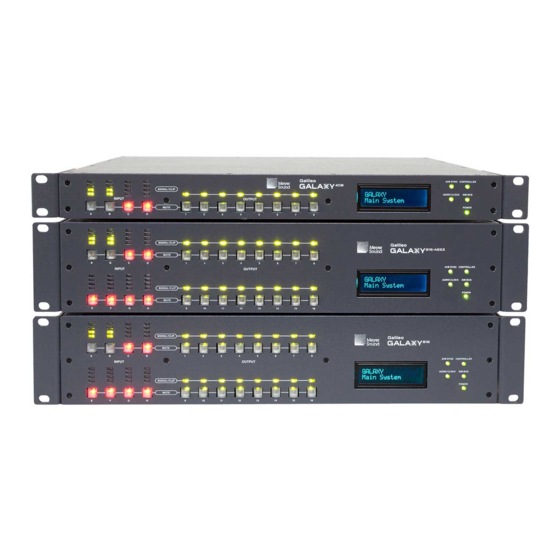
- Page 1 USER GUIDE CREATE Galileo GALAXY 408 Galileo GALAXY 816 Galileo GALAXY 816-AES3 Keep these important operating instructions. Check www.meyersound.com for updates.
- Page 2 The contents of this manual are furnished for informational purposes only, are subject to change without notice, and should not be construed as a commitment by Meyer Sound Laboratories Inc. Meyer Sound assumes no responsibility or liability for any errors or inaccuracies that may appear in this manual.
-
Page 3: Important Safety Instructions
2. Keep these instructions. 12. Use only with the caster rails or rigging specified by 3. Heed all warnings. Meyer Sound, or sold with the apparatus. Handles are 4. Follow all instructions. for carrying only. 5. Do not use this apparatus near water. -
Page 4: Powercon Use
Wassereinwirkung oder übermäßig hoher Luft- feuchtigkeit ausgesetzt werden könnte, solange es sich nicht um ein Produkt handelt, dass mit der Meyer Sound English Weather Protection Option ausgestattet ist. • To reduce the risk of electric shock, disconnect the •... - Page 5 GALILEO GALAXY USER GUIDE pas à proximité de sources de chaleur, radiateur ou four reparaciones deben ser realizadas únicamente por per- par exemple. sonal de servicio capacitado de fábrica. • S'il est équipé d'un porte-fusible externe, le fusible rem- plaçable est le seul élément qui peut être réparé par l'utilisateur.
- Page 6 IMPORTANT SAFETY INSTRUCTIONS...
-
Page 7: Table Of Contents
English Deutsch Français Español Chapter 1: Introduction How to Use This Manual Meyer Sound Technical Support Galileo GALAXY Network Platform Powerful Audio Processing Extensive User Control Milan-Certified Network Platform Galileo GALAXY Network Platform Features Overview GALAXY 816 Processor Input/Output Summary... - Page 8 CONTENTS Environment Access Low-Mid Beam Control Link Groups Input Processing Tab Channel Settings Parametric U-Shaping Output Processing Tab Channel Settings Parametric U-Shaping All Pass Filters Summing Matrix Tab Matrix Modes: Summing or Direct Routing Summing Matrix Operation Color Coding Delay Matrix Tab Input Masters Tab Output Masters Tab System Tab...
- Page 9 GALILEO GALAXY USER GUIDE Appendix D: Low-Mid Beam Control Array Name Status Control Type Elements Per Output Start On Output Number of Elements Element Location Product Type Array Splay Associated Outputs Tips For Using LMBC Appendix E: Atmospheric Correction Overview Using The GALAXY Processors Environmental Conditions Settings Appendix F: Keyboard Shortcuts Interaction with Linking Modes...
- Page 10 CONTENTS...
-
Page 11: Chapter 1: Introduction
Information and specifications are subject to change. Updates and supplementary information are available at www.meyersound.com. MEYER SOUND TECHNICAL SUPPORT Meyer Sound Technical Support is available at: Tel: +1 510 486.1166 • Tel: +1 510 486.0657 (after hours support) •... -
Page 12: Galileo Galaxy Network Platform
The rear panel includes SIM 3 bus port(s) (one on the GALAXY 408 processor and two on both the GALAXY 816 processor and the GALAXY 816-AES3 processor) for direct connection to Meyer Sound’s SIM audio analyzer, allowing GALAXY processors to function as line switchers for the analyzer. With this capability, users can take measurements from any selection of GALAXY processor inputs and outputs without patching beyond a single connection to SIM. -
Page 13: Galileo Galaxy Network Platform Features Overview
GALILEO GALAXY USER GUIDE Galileo GALAXY Network Platform Features Overview GALAXY processors include the following features: Complete system control, optimization, and monitoring with Compass Control Software for Mac and Windows-based • computers Mobile system control, optimization, and monitoring with the Compass Go application for iPad •... -
Page 14: Galaxy 816 Processor Input/Output Summary
8 outputs that can provide processed analog signals • 16 outputs that can provide processed AVB signals via XLR connectors • 6 output sources, each capable of sourcing an 8-channel AVB stream via RJ-45 connectors • Galileo GALAXY 408 Processor Front and Rear Panels... -
Page 15: Galaxy 816-Aes3 Processor Input/Output Summary
GALILEO GALAXY USER GUIDE GALAXY 816-AES3 Processor Input/Output Summary The GALAXY 816-AES3 processor is a 2RU, 19-inch rack mountable device with the following inputs/outputs: 8 inputs that can receive analog, AES3, or AVB signals • 24 AVB unprocessed matrix inputs •... - Page 16 CHAPTER 1: INTRODUCTION...
-
Page 17: Chapter 2: Galaxy Enclosures And I/O
GALILEO GALAXY USER GUIDE CHAPTER 2: GALAXY ENCLOSURES AND I/O All three GALAXY processors offer the same processing on inputs and outputs but differ in their size and physical connections. The GALAXY 816-AES3 processor also includes a BNC connector for external word clock input. GALAXY PROCESSOR ENCLOSURES The three GALAXY processors are designed to be mounted in 19-inch wide racks. -
Page 18: Front Panel Processed Inputs Section
CHAPTER 2: GALAXY ENCLOSURES AND I/O Front Panel Processed Inputs Section The GALAXY processor front panel processed inputs section is on the left side (Figure 2) and consists of input level meters and input mute buttons. Input Level Meters Input Mute Buttons Figure 2: GALAXY Processor Front Panel Processed Inputs Section Input Level Meters: Four-segment LED ladders represent the level for each input channel. -
Page 19: Front Panel Processed Outputs Section
GALILEO GALAXY USER GUIDE Front Panel Processed Outputs Section The GALAXY processor front panel processed outputs section is in the middle (Figure 3) and consists of output signal/clip LEDs and output mute buttons. Signal / Output Mute Clip LEDs Buttons Figure 3: GALAXY Processor Front Panel Processed Outputs Section Signal / Clip LEDs: Output level is indicated by one multi-color LED for each output channel. - Page 20 CHAPTER 2: GALAXY ENCLOSURES AND I/O Front Panel Display: The front panel display provides the device name, current snapshot, device identity indicator, and • other critical device notifications available on the GALAXY. Use the Front Panel Display Control in Compass to adjust the brightness and color.
-
Page 21: Galaxy Processor Rear Panels
AES mode (i.e., when input A is set to AES mode, input B is disabled). Analog Output Connectors (1–16): Sixteen XLR-3M connectors route audio to Meyer Sound self-powered •... -
Page 22: Galaxy 408 Processor Rear Panel Connectors
(A, C) to receive two-channel audio signals. The analog-only inputs are disabled when their input pair is set to AES mode (i.e., when input A is set to AES mode, input B is disabled). Analog Output Connectors (1–8): Eight XLR-3M connectors route audio to Meyer Sound self-powered loudspeakers, •... -
Page 23: Galaxy 816-Aes Processor Rear Panel Connectors
AES3 digital outputs (two channels per output: 1–2, 3–4, etc.). Use only cables rated for AES signals to connect these outputs to the inputs of AES3 devices. Analog Output Connectors (9–16): The bottom row has eight XLR-3M connectors to route audio to Meyer Sound self- •... -
Page 24: Power Connector
CHAPTER 2: GALAXY ENCLOSURES AND I/O SIM 3 Bus Connectors: Connects to the SIM audio analyzer so the GALAXY’s inputs and outputs can be used as • measurement points. A second SIM 3 bus port is provided to loop an additional GALAXY or to a SIM-3088 line-level switcher. -
Page 25: Sim 3 Connectors
GALILEO GALAXY USER GUIDE SIM 3 CONNECTORS The GALAXY rear panel includes a bus port for direct connection to the SIM audio analyzer. The GALAXY can then act as a line switcher for the analyzer and measure across any selection of inputs and outputs without additional patching. Figure 9: GALAXY Processor SIM 3 connectors: Connection to SIM and/or Looping to other GALAXY Processors (second looping connector not available on the GALAXY 408 Processor) The default bus address for the GALAXY processor is 10 and the available range is 0–14. -
Page 26: Client Computer Connection
1. Locate the USB drive delivered with the GALAXY processor. The drive contains the version of Compass that matches the version of firmware installed in the GALAXY processor. Or, download the latest version of Compass Control Software from the Meyer Sound website: https://meyersound.com/product/compass/#software There is a registration procedure for first-time web site users. - Page 27 GALILEO GALAXY USER GUIDE 5. Start the Compass application on the computer. The default user interface for Compass is shown in Figure 11. Top Tabs Top Tab Control Buttons Figure 11: Compass Default Landing GUI At this tab interface, the user can set a wide variety of preferences, including which tabs to show along the top of the Compass interface.
-
Page 28: Galaxy Processors In A Network Configuration
CHAPTER 2: GALAXY ENCLOSURES AND I/O Figure 12: Processor Tab Landing Window NOTE: The Client/Server connection between GALAXY processors does not require setting IP Addresses. Compass uses IPv6 to connect to the processors. If the switches are properly configured and the cabling is correctly routed, Compass will automatically connect to the GALAXY processors. -
Page 29: Chapter 3: Controlling Galaxy Processors With Compass
Compass Go is an iPad application, a light version of the Compass Control Software. It provides all the key functionalities of Compass with maximum mobility. NOTE: Meyer Sound has developed videos to provide an overview of Compass Control Software; please visit https://meyersound.com/videos/#support NOTE: Meyer Sound Compass 4.3.6, Compass Go AM824, and their included GALAXY processor firmware... -
Page 30: Galaxy Processor User Interface
Compass has context help available within the program. Look for a gray button labeled “Help,” or on the denser screens, a gray button with a small “?” on it. TIP: Meyer Sound has developed system example videos for the GALAXY processor that provide a good introductory overview. Visit: https://meyersound.com/videos/#support Inventory Tab Users can add, connect, and configure GALAXY processors within the Inventory tab. -
Page 31: Upgrading Firmware
GALILEO GALAXY USER GUIDE Launch “Virtual” mode to work on a project without being connected to a real GALAXY processor (this feature also • supports a demo mode with simulated meter values that sweep up and down) Select whether a GALAXY processor is displayed in the main Compass window or a secondary window •... -
Page 32: Overview Tab
CHAPTER 3: CONTROLLING GALAXY PROCESSORS WITH COMPASS Overview Tab The Overview tab is shown in Figure 15. It provides a high level view of GALAXY processor settings. The basic input and output settings can be modified by clicking, entering new values, or click-dragging controls. Many of the graphic elements are shortcuts to other tabs or open dialogs: Input Processing, Summing Matrix, Output Processing, Product Integration Dialog, and Atmospheric Correction Dialog. - Page 33 GALILEO GALAXY USER GUIDE CAUTION: Opening a project file in the Compass Control Software when the computer is connected to a GALAXY processor overwrites all stored Snapshots and the current device settings of the GALAXY processor if Load Device Settings is selected when the GALAXY Project is opened. To merge snapshots from another Project file into the current Snapshot library in a GALAXY processor, use the Merge Project option from the Project tab (click the More>>...
-
Page 34: Settings Tab
CHAPTER 3: CONTROLLING GALAXY PROCESSORS WITH COMPASS Settings Tab The Settings tab has eight sub-tabs: Network, Input and Output, SIM, Environment, Access, Low-Mid Beam Control, Link Groups, and Log. Network The Network tab lists the GALAXY processor Device Type, Entity Name, Group Name, Serial Number, IPv6 Address, IPv4 Address, MAC Address, Front Panel Display Color and Brightness, Date and Time, Operating Mode Indicator, Soft Reboot Options, Upload Firmware options, and Edit Network Settings options. - Page 35 GALILEO GALAXY USER GUIDE AVB Control Mode: network digital source signals may be connected to the AVB/Network port connectors (labeled 1 and • 2) on the GALAXY processor rear panel. These connectors allow for the usage of Milan-compliant AAF streams for Audio (see the AVB Networking Guide, available at https://meyersound.com/documents).
-
Page 36: Sim
Low-Mid Beam Control is a tool for GALAXY processor users to modify the natural vertical coverage of the Low to Mid Frequencies of a Meyer Sound line array (up to 32 elements) to more closely match the high frequency coverage (see Appendix D, “Low-Mid Beam Control”). -
Page 37: Log
The Log tab displays a date- and time-stamped running record of a GALAXY processor’s operation. This display is a subset of all log data (includes client level messages). For a more detailed log history (that might help Meyer Sound Tech Support, for example, in a debug situation), use the Save System Logs button under the Settings tab. -
Page 38: Input Processing Tab
CHAPTER 3: CONTROLLING GALAXY PROCESSORS WITH COMPASS Input Processing Tab The display under the Input Processing tab (Figure 17) is divided into two sections. The upper part provides a Plotter display, where a user can visualize input channel equalization. The plotter plots gain (left vertical axis) and phase (right vertical axis) against frequency (x-axis). -
Page 39: Channel Settings
GALILEO GALAXY USER GUIDE Channel Settings Under the Channel Settings tab in Input Processing (see Figure 17, lower half), the user can set a Label, Gain value, Delay Value, Mute the Channel, and enable or bypass Parametric, U-Shaping, and/or all EQ for a particular input channel. Select the Input Channel to control via the drop-down menu or individual alphabetic channel buttons (e.g., A-H for a GALAXY 816 processor) above the plotter display. -
Page 40: U-Shaping
CHAPTER 3: CONTROLLING GALAXY PROCESSORS WITH COMPASS Figure 18: Processor > Input Processing > Parametric and U-Shaping tabs U-Shaping Controls for U-shaping are located within a tab also in the lower half of the Input Processing tab (Figure 18). The U-Shaping filter has five gain bands and four frequency breakpoints. -
Page 41: Output Processing Tab
GALILEO GALAXY USER GUIDE Output Processing Tab Similar to the Input Processing tab, the Output Processing tab (Figure 19) allows a user to visualize and edit output channel equalization and settings. The upper part of the display is the plotter, the lower part the control. The plotter plots gain (left vertical axis) and phase (right vertical axis) against frequency (x-axis). -
Page 42: Channel Settings
CHAPTER 3: CONTROLLING GALAXY PROCESSORS WITH COMPASS Channel Settings Under the Channel Settings tab in Output Processing (see Figure 19, lower half), the user can set a Label, Gain value, Delay Value, Mute the Channel, and enable or bypass Parametric, U-Shaping, All Pass Filtering, and/or all EQ for a particular output channel. -
Page 43: Parametric
GALILEO GALAXY USER GUIDE Parametric Parametric controls may be set via a tab in the lower half of the Output Processing tab (Figure 19). Output Parametric EQ has 10 bands. Each band has four settings: Bypass, Frequency, Bandwidth and Gain. Bypass allows the user to bypass an individual parametric EQ band for that channel. - Page 44 CHAPTER 3: CONTROLLING GALAXY PROCESSORS WITH COMPASS Figure 20: Processor > Output Processing > U-Shaping and All Pass tabs...
-
Page 45: Summing Matrix Tab
GALILEO GALAXY USER GUIDE Summing Matrix Tab The Summing Matrix (Figure 21) allows the user to route inputs to outputs within the processor. A maximum of 232 out of 512 connections between input channels and output channels (cross-points) can be made in the Summing Matrix tab. Each input channel can be level adjusted independently to individual output channels. -
Page 46: Color Coding
CHAPTER 3: CONTROLLING GALAXY PROCESSORS WITH COMPASS Color Coding Negative gain values scale from light gray to dark gray. Positive gain values scale from dark olive to light olive. There is a color legend below the matrix. Delay Matrix Tab Delay times may be assigned to each matrix cross-point in the Delay Matrix tab (Figure 22). -
Page 47: Input Masters Tab
GALILEO GALAXY USER GUIDE Input Masters Tab The Input Masters tab (Figure 23) provides fader controls to adjust the signal levels of the Inputs by decibels (dB). Clicking above or below the handle results in single dB increments or decrements; clicking on a dB value to the right of the control will cause the gain to jump to that value. -
Page 48: Output Masters Tab
CHAPTER 3: CONTROLLING GALAXY PROCESSORS WITH COMPASS Output Masters Tab The Output Masters tab (Figure 24) provides fader controls for adjusting the signal levels of the Outputs by decibels (dB). Clicking above or below the handle results in single dB increments or decrements; clicking on a dB value to the right of the control will cause the gain to jump to that value. -
Page 49: System Tab
GALILEO GALAXY USER GUIDE SYSTEM TAB The System tab allows a user to view settings for multiple GALAXY processors simultaneously in one window. It is read-only. Under the Inventory tab, select the processors to display by clicking on the small buttons to the far right of each device row (Figure 25). - Page 50 CHAPTER 3: CONTROLLING GALAXY PROCESSORS WITH COMPASS...
-
Page 51: Chapter 4: Galileo Galaxy Network Platform Specifications
GALILEO GALAXY USER GUIDE CHAPTER 4: GALILEO GALAXY NETWORK PLATFORM SPECIFICATIONS SPECIFICATION TABLE GALILEO GALAXY 408 GALILEO GALAXY 816 GALILEO GALAXY 816-AES3 INPUTS 4 gold-plated XLR-F, 2 RJ-45 network Input Connectors 8 gold-plated XLR-F, 2 RJ-45 network ports ports 4 processed inputs selectable as... -
Page 52: Galileo Galaxy Network Platform Parts And Accessories
CHAPTER 4: GALILEO GALAXY NETWORK PLATFORM SPECIFICATIONS MATRIX Summing Matrix Sparse 32 x 16 Summing Matrix (up to 232 of 512 cross-points can be set simultaneously Delay Matrix Sparse 32 x 16 Delay Matrix; 500 ms delay range at each cross-point (nonfading) PROCESSING Digital Conversion 24-bit resolution, 96 kHz sample rate... -
Page 53: Dimensions
GALILEO GALAXY USER GUIDE DIMENSIONS 16.90 in [429 mm] 15.90 in [404 mm] .08 in 19.00 in [483 mm] [2 mm] 3.47 in [88 mm] GALAXY 816 & 816-AES3 16.21 in [412 mm] 19.00 in .08 in [483 mm] [2 mm] 1.72 in [44 mm] 16.21 in... - Page 54 CHAPTER 4: GALILEO GALAXY NETWORK PLATFORM SPECIFICATIONS...
-
Page 55: Appendix A: Audio Signal Flow
GALILEO GALAXY USER GUIDE APPENDIX A: AUDIO SIGNAL FLOW As noted earlier, all GALAXY processors offer the same processing for audio signals. However, the inputs and outputs are different, so the signal flow is also slightly different. This appendix provides signal flow diagrams for all three processors and a few more details about terminology. -
Page 56: Galaxy 816 Processor Audio Signal Flow
APPENDIX A: AUDIO SIGNAL FLOW GALAXY 816 PROCESSOR AUDIO SIGNAL FLOW Figure 27 illustrates the audio signal flow for a GALAXY 816 processor. For details about clocking, see Appendix B, “Clocking.” AUDIO SIGNAL FLOW GALAXY 816 GALAXY OUTPUTS GALAXY Simultaneous Milan AVB and analog outputs INPUTS 32 Unique Audio ETHERNET... -
Page 57: Galaxy 408 Processor Audio Signal Flow
GALILEO GALAXY USER GUIDE GALAXY 408 PROCESSOR AUDIO SIGNAL FLOW Figure 28 illustrates the audio signal flow for a GALAXY 408 processor. For details about clocking, see Appendix B, “Clocking.” GALAXY 408 AUDIO SIGNAL FLOW GALAXY OUTPUTS GALAXY Simultaneous Milan AVB and analog outputs INPUTS 32 Unique Audio ETHERNET... -
Page 58: Galaxy 816-Aes Processor Audio Signal Flow
APPENDIX A: AUDIO SIGNAL FLOW GALAXY 816-AES PROCESSOR AUDIO SIGNAL FLOW Figure 29 illustrates the audio signal flow for a GALAXY 816-AES processor. For details about clocking, see Appendix B, “Clocking.” AUDIO SIGNAL FLOW GALAXY 816 AES GALAXY OUTPUTS GALAXY Simultaneous Milan AVB and analog outputs INPUTS 32 Unique Audio... -
Page 59: Appendix B: Clocking
GALILEO GALAXY USER GUIDE APPENDIX B: CLOCKING MEDIA CLOCK FOR A SINGLE GALAXY PROCESSOR NOTE: “Media Clock” is the common terminology used in the Milan specification. Within the GALAXY processor Settings: Input and Output tab, the Media Clock choice is selected under the “System Clock: Clock Mode”... -
Page 60: Common Media Clock For Multiple Interconnected Galaxy Processors
APPENDIX B: CLOCKING COMMON MEDIA CLOCK FOR MULTIPLE INTERCONNECTED GALAXY PROCESSORS When connecting multiple GALAXY processors together, it is imperative that one common media clock be used. Clocks should never be daisy-chained. Even small timing differences can cause audio degradation that is audible. Figure 31, Figure 32, and Figure 33 illustrate some of the more common multiple GALAXY processor clocking configurations for networked GALAXY processors. - Page 61 GALILEO GALAXY USER GUIDE NOTE: An AAF Clock may also be sent from GALAXY A as a Media Clock, but the CRF clock is preferable as it is more bandwidth efficient. GALAXY B GALAXY D AES3* Milan AVB/AES Milan AVB GALAXY A System Clock: System Clock: System Clock:...
-
Page 62: Digital Latency
To ensure proper alignment, measure the delay between the local GALAXY processor’s physical analog outputs to any remote GALAXY processor(s) physical analog outputs using an accurate audio analyzer (such as Meyer Sound’s SIM System). INPUT SAMPLE RATES With the ASRC enabled, the GALAXY processor can accept a range of sample rates for AES inputs (see Table 4). -
Page 63: Appendix C: Product Integration
GALILEO GALAXY USER GUIDE APPENDIX C: PRODUCT INTEGRATION PRODUCT INTEGRATION Product Integration combines both Delay Integration and Starting Point settings in a single dialog. Using Product Integration is the first step to complete when optimizing a system. It is not recommended for use when a system has previously been optimized, as some or all of the output processing filters and settings may be over-written. -
Page 64: Product Integration By Loudspeaker
Product Integration is available on every GALAXY processor output. The native phase curves exhibited by Meyer Sound products can be differentiated by the lowest frequency at which each product deviates by 180 degrees of relative phase. Product Integration uses the concept of phase curve families shared by different products: For example, LYON (see Figure 34, red line) and LEOPARD loudspeakers both have a low-mid phase response of 180 degrees at 55 Hz (pc55-70);... -
Page 65: Technical Notes
Although the M Series phase response is 180 degrees at 350 Hz, it can be improved by using pc125 when used in close • proximity to other Meyer Sound loudspeakers. When Product Integration is applied to subwoofer outputs, the phase slope is optimized to align with the mid-high •... - Page 66 APPENDIX C: PRODUCT INTEGRATION...
- Page 67 The result is more consistent coverage across the entire operating range of the array. For an in-depth explanation of the theory behind LMBC please watch the video on the Meyer Sound website: https://meyersound.com/videos/#support LMBC should always be modeled in MAPP so that performance can be evaluated before it is implemented.
- Page 68 APPENDIX D: LOW-MID BEAM CONTROL Under the Low-Mid Beam Control tab, there are a number of settings the user can control: Array Name Each line array being driven by this processor can be named for quick identification by clicking in the Array Name widget and entering the appropriate text.
- Page 69 GALILEO GALAXY USER GUIDE NOTE: The splay angle between the top grid and the first element should be set to 0 degrees. Associated Outputs The Associated Outputs dialog box displays the processor outputs associated with an array’s LMBC processing. It also provides All Pass filter parameters (center frequency and Q) that can be applied to fill loudspeakers connected to other processor outputs to optimize alignment with the line array system using LMBC.
- Page 70 APPENDIX D: LOW-MID BEAM CONTROL Once LMBC has been enabled, the All Pass filters can be seen on each Output Processing Channel, and via the (output) Processing thumbnails on the left side of the Overview tab. Figure 37: The Processing Column on the Overview tab Indicates the LMBC All Pass Filters TIPS FOR USING LMBC Signal drive lines must have correct polarity.
- Page 71 GALILEO GALAXY USER GUIDE APPENDIX E: ATMOSPHERIC CORRECTION OVERVIEW The GALAXY processor’s Atmospheric Correction function uses atmospheric loss equations and pre-calculated values to maintain system response as temperature and humidity vary. The correction coefficients are determined by user-entered parameters: the environmental conditions, and unique to each output, Atmospheric Gain Factor and Distance. Air absorption of sound is a complex, non-intuitive function, of which temperature, humidity, and distance have the most effect, changing how well higher frequency sounds propagate through air.
- Page 72 APPENDIX E: ATMOSPHERIC CORRECTION Figure 39 provides frequency attenuation curve examples for three different temperatures with a fixed distance of 100 meters, at seven values for relative humidity. Depending on the atmospheric conditions and the distance the array is throwing, the number of possible correction combinations can be quite large, but they are achievable with the GALAXY processor.
- Page 73 GALILEO GALAXY USER GUIDE The GALAXY processor’s Atmospheric Correction filter function is limited to a maximum of 14 dB of boost when the Atmospheric Gain Factor is set to 100%. Atmospheric Correction does not try to correct to the highest frequencies. It is constrained to the range of frequencies that can be practically corrected, preserving headroom, unlike using a shelving filter.
- Page 74 APPENDIX E: ATMOSPHERIC CORRECTION USING THE GALAXY PROCESSORS ENVIRONMENTAL CONDITIONS SETTINGS To use the Atmospheric Correction function, the user must first set the environmental conditions. To do so: 1. Select a GALAXY processor in Compass 2. Select the Settings > Environment tab (Figure 41). Figure 41: Environment Tab Settings From this tab the user can enter the current temperature and humidity, and select the appropriate altitude range.
- Page 75 GALILEO GALAXY USER GUIDE To apply Atmospheric Correction: 1. Select an output processing channel under the Output Processing tab. By default, the correction filters will not be shown in the plotter. 2. To make the filters visible, select the Response mini tab to the right of the plot, and check the box labeled “Atmos.
- Page 76 APPENDIX E: ATMOSPHERIC CORRECTION Figure 43: Atmospheric Correction Enabled and Displayed...
- Page 77 GALILEO GALAXY USER GUIDE APPENDIX F: KEYBOARD SHORTCUTS Keyboard shortcuts are available and summarized below. Interaction with Linking Modes Global and local linking preferences affect which channels are modified by keyboard shortcuts: Global Device Select-Linking Mode—If the Global Device Select-Linking Mode is set to “All channels on the active •...
- Page 78 APPENDIX F: KEYBOARD SHORTCUTS Link All Channels Changes made to one input channel will affect all input channels; the same controls apply for output channels. Control-Shift (Command-Shift on Mac) = All Channels. Changes made to all channels in a device. •...
- Page 79 GALILEO GALAXY USER GUIDE APPENDIX G: GLOSSARY The following defines some of the terms used in the Compass Control Software GALAXY processor User Interface. AVTP (Audio Video Transport Protocol) Audio Format A device that is capable of receiving AVB streams from an AVB Talker. All available streams from all available AVB Listener AVB Talkers that have the same Group Name on the network will selectable by the AVB Listener as inputs.
- Page 80 APPENDIX G: GLOSSARY A Snapshot contains all of the control point values captured, named, and stored in the GALAXY processor hardware. When Snapshots are recalled, all of the control point values of GALAXY processor are overwritten Snapshot with the stored values, with the possibility to exclude some parameters via the confirmation dialog. Snapshots are listed in the Snapshot Library on the Project tab and are limited to a maximum of 255.
- Page 81 This Class B digital apparatus complies with Canadian ICES-003. Cet appareil numérique de la classe B est conforme à la norme NMB-003 du Canada. GALAXY 408 EMC FCC DECLARATION OF CNFRMTY Meyer Sound Document Number 01.237.001.03 Revision A Dated 2016-8-26 Page 1 of 1...
- Page 82 This Class B digital apparatus complies with Canadian ICES-003. Cet appareil numérique de la classe B est conforme à la norme NMB-003 du Canada. GALAXY 816 SERIES EMC FCC DECLARATION OF CONFORMITY Meyer Sound Document Number 01.230.001.03 Revision B Dated 2017-3-17 Page 1 of 1...
- Page 84 Meyer Sound Laboratories Inc. 2832 San Pablo Avenue Berkeley, CA 94702 © 2019 Meyer Sound Laboratories. All rights reserved. www.meyersound.com Galileo GALAXY User Guide PN 05.230.005.01 D T: +1 510 486.1166...
Need help?
Do you have a question about the Galileo GALAXY 408 and is the answer not in the manual?
Questions and answers