Table of Contents
Advertisement
Thank you for purchasing our product.
To use this product safely and properly, please read this manual carefully.
Keep this manual at hand.
● Never use this product as a sensing device for personnel protection.
● In case of using sensing devices for personnel protection, use products which meet laws and
standards, such as OSHA, ANSI or IEC etc., for personnel protection applicable in each region
WARNING
or country.
Contents
1
2
3
4
5
6
7
8
9
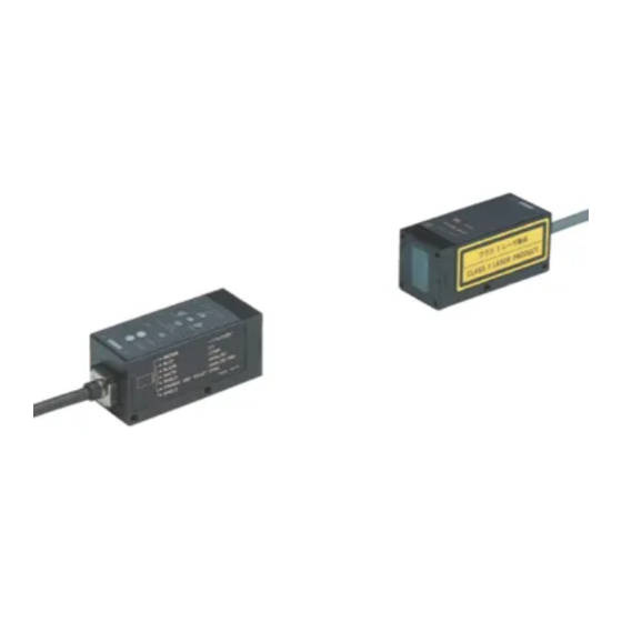
Instruction Manual
Laser Beam Sensor
・・・・・・・・・・・・・・・・・・・・・・・
・・・・・・・・・・・・・・・・・・・・・・・・
・・・・・・・・・・・・・・・・・・・・・・・・・ ・・・・
・・・・・・・・・・・・・・・・・・・・・・・・・ ・・・・
・・・・・・・・・・・・・・・・・・・・・・・・・・・
・・・・・・・・・・・・・・・・・・・・・ ・・・・・・
・・・・・・・・・・・・・・・・・・・・・ ・・
・・・・・・・・・・・・・・・・・・・・・・・・・・・
LA-511
・・・・・・・・・・・・・・・・・・・・
・・・・・・・・・・・・・・ ・
・・・・・・・・・・・・・・・・ ・
Page
・・・・・・
・・・・・・・・・
ME-LA3_LA-511(05) No. 0044-13V
1
2
3
4
5
6
8
8
9
10
10
11
13
Advertisement
Table of Contents

Subscribe to Our Youtube Channel
Related Manuals for Panasonic LA-511


Summary of Contents for Panasonic LA-511
-
Page 1: Table Of Contents
Instruction Manual Laser Beam Sensor LA-511 Thank you for purchasing our product. To use this product safely and properly, please read this manual carefully. Keep this manual at hand. ● Never use this product as a sensing device for personnel protection. -
Page 3: For Safe Use Of Laser Products
For safe use of laser products ●FDA (Food and Drug Administration, U.S.DHHS) part 1040 “Performance standards for light-emitting products” has been established for the purpose of preventing users from suffering injuries by laser products. This product belongs to “Class 1 laser product” according to the degree of the hazard specified in the classification system of FDA Standards 21CFR 1040.10 and 1040.11. -
Page 4: Laser Radiation Fields
Laser Radiation Fields VIEW FROM TOP 500mm 21mm 13mm PLAN 1 500mm LA-511D LA-511P 30mm Sensor Detector Sensor Projector 22mm : Laser radiation fields 1: MONITOR (Beam Alignment Monitor) 2: OUT (Operation Indicator) 3: SPAN (Span Adjustor) 4: SENS. (Comparison Level Adjustor) 5: POWER (Radiation Emission Indicator) -
Page 5: Major Specifications
Major Specifications Type Thru-beam Item Model No. LA-511 Sensing Width 15mm Sensing Distance 500mm Repeat Accuracy Power Source 12 to 24V DC ±10%, Ripple : 10% P-P or less 60mA or less Current Consumption ・Output voltage : ※ 1V (When all beam interrupted) to 5V (When all beam received) Analog Voltage ・Through rate : 8V/ms or over... -
Page 6: Cautions
Doing so may cause malfunctions from inductive interference. ●LA-511 employs a line-bypass capacitor system to enhance electrical noise resistance. If there is any equipment near the sensor such as supersonic welding machine which produces a high frequency noise, and in addition, if sensor mounting framework is electrically conductive, an insulation is required between the sensor and the framework. -
Page 7: Mounting
Mounting ●Since laser beam has a directional property, special care must be taken to the direction of the sensor when mounting. [Detector] [Projector] (Note 1) The tightening torque should be 1.17N・m{12kgf・cm} or less. (Note 2) When mounting sensors using provided mounting brackets, secure firmly both sides of the sensors with a pair of brackets. -
Page 8: Connections
Connections ●I/O Circuit Diagram Projector Color of leads +V (Brown) Sync. (Orange and Violet) + 12 to 24V DC SHIELD ±10% - Remote interlock (Pink) 0V (Blue) 0.022μF External Connection Example Internal Circuit Detector +V (Brown) Sync. (Orange and Violet) SHIELD 75Ω... - Page 9 ●Remote Interlock Input When the remote interlock input (pink lead) is connected to 0V, the laser beam is emitted (when it is either opened or connected to +V, the laser emission goes out). You can make use of this procedure as one of daily checks before starting operation or if you need to use a laser beam.
-
Page 10: Adjustments
Adjustments <Name and function of Each Section> Operation Indicator Radiation Emission Indicator Comparison Level Adjustor Beam Alignment Monitor Yellow LED ・・・ 4 PCS. Span Adjustor Green LED ・・・ 1 PC. [Projector] ●Remote Interlock Cord: As required by the requirements of the Radiation Safety Standards, laser radiation stops when it is left opened or connected to +V. -
Page 11: Beam Alignment
<Beam Alignment> ●Temporarily set projector and detector in their required position with the projecting eye facing the detector. Make the following adjustments watching the beam alignment monitor on detector. [Action of the beam alignment monitor] ●Move detector in the direction indicated by the yellow illuminated arrowheads until the indication going out. -
Page 12: Span Adjustment (Adjustment Of Analog Output Voltage)
<Span Adjustment (adjustment of analog output voltage) > Green LED glows 1. Place sensors in all beam incoming state. On the monitor, the green LED glows and all yellow arrowheads remain extinguished. 2. Turn the span adjustor with the screwdriver provided to obtain +5V of analog output voltage. -
Page 13: Dimensions
Dimensions (Unit:mm) ●LA-511P (Projector) Radiation Emission Indicator φ5.7 cable 3m 13.7 4-M3P0.5 tapped, 6mm depth (3.2) 31.8 2-M4P0.7 tapped, 10mm depth (both side) 2-M40.7 tapped, 4mm depth ●LA-511D (Detector) 18.5 12.4 12.4 Beam Alignment Monitor Operation Indicator Comparison Level Adjustor Span Adjustor (1)... - Page 14 ●LA-511+MS-LA1 (72) 27.8 41.8 25.8 23.5 t 1.6...
-
Page 15: Side-View Attachment (La-Sv1)(Optionally Available)
Side-View attachment (LA-SV1)(optionally available) ●When using the side-view attachment, mount it on either projector or detector. If mounting the attachment on both units, one or more of yellow LED indicators, beam alignment monitor, may not go out. ●The side-view attachment always must be mounted under the condition that the radiation indicator is not glowing. - Page 16 Overseas Sales Division (Head Office) 2431-1 Ushiyama-cho, Kasugai-shi, Aichi, 486-0901, Japan Phone: +81-568-33-7861 FAX: +81-568-33-8591 About our sale network, please visit our website. PRINTED IN JAPAN © Panasonic Industrial Devices SUNX Co., Ltd. 2014...
Need help?
Do you have a question about the LA-511 and is the answer not in the manual?
Questions and answers