Table of Contents
Advertisement
Quick Links
Advertisement
Chapters
Table of Contents

Related Manuals for Vinten Vision 8


Summary of Contents for Vinten Vision 8
- Page 1 Contents Next Previous Page View Vision 8 (Black) Vinten Camera Control Solutions...
- Page 2 Vinten Broadcast Limited. Vinten, Vision and Quickfit are registered trademarks of Vinten Broadcast Limited.
- Page 3 Particular attention must be paid to cleaning, especially after use in adverse conditions. To order spare parts or to obtain further information, application should be made to Vinten Broadcast Limited or to your local distributor.
- Page 4 Page View Notes to readers This is the on-line version of ‘Vision 8 (Black) Pan and Tilt Head Maintenance Manual’ (3841-9). Readers should be aware that the pagination differs between on-line and printed versions. Navigation Clicking the mouse on any blue text will move you around the document.
- Page 5 Contents First Previous Next Previous Page Page Page View Safety - Read This First! Warning symbols in this maintenance manual Where there is a risk of personal injury, injury to others, or damage to the pan and tilt head or associated equipment, comments appear, highlighted by the word WARNING! and supported by the warning triangle symbol.
- Page 6 Main assembly part numbers ............35 Associated Publication Vision 8 (Black) Pan and Tilt Head - Operators Guide Publication Part No 3841-8...
-
Page 7: Table Of Contents
Fig 6.4 Vision 8 (Black) Pan and Tilt Head - Tilt Drag Unit Assembly...... - Page 8 Contents First Previous Next Previous Page Page Page View Abbreviations The following abbreviations are used in this publication: alternating current pound (weight) Amps Lubricated Friction across flats left hand as required MISO metric thread ASME American Society of Mech Engineers metre assy assembly...
- Page 9 Contents First Previous Next Previous Page Page Page View Technical Specification Weight Head 2.7 kg (5.9 lb) Pan bar 0.2 kg (0.4 lb) Bowl clamp) 0.14 kg (0.3 lb) Height to mounting face 15 cm (5.9 in.) Length 14 cm (5.5 in.) Width 12.5 cm (4.9 in.) Load capacity...
- Page 10 Contents First Previous Next Previous Page Page Page View Design Improvements SERIAL No. DETAILS INFORMATION...
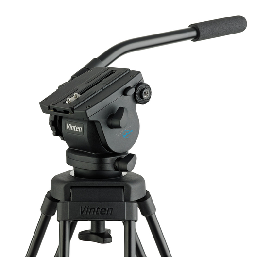
- Page 11 Description ................3 Introduction The Vision 8 (Black) pan and tilt head is part of a range designed for broadcast professional, corporate and educational use. It is constructed largely in aluminium and magnesium alloys to produce a robust, lightweight unit.
-
Page 12: Fig 1.1 Vision 8 Pan And Tilt Head
Contents First Previous Next Previous Page Page Page View (15) (14) (13) (12) (11) (10) Fig 1.1 Vision 8 Pan and Tilt Head... - Page 13 Contents First Previous Next Previous Page Page Page View A ball base and clamp for mounting on a 100 mm bowl is provided. An illuminated level bubble fitted at the rear of the head, lit by pressing the switch (12). The battery for the light is housed in a compartment in the top of the mechanism housing, closed by a cap (10).
-
Page 14: General
8 (Black) Operators Guide, Publication Part No. 3841-8. Installing the head on a tripod The Vision 8 head is supplied with an integral 100 mm ball mount and is designed for installation on a compatible Vinten Vision tripod. Adaptors are available which enable the heads to be installed on tripods or pedestals fitted with other mountings. -
Page 15: Fig 2.1 Optional Quickfit Adapter
Contents First Previous Next Previous Page Page Page View Mounting the camera (optional Quickfit adaptor) To mount the camera using the optional Quickfit adaptor, proceed as follows (Fig 2.1): If not already attached, secure the Quickfit adaptor (17) to the slide plate (11) with the two screws provided (5). -
Page 16: Fig 2.2 Balance Graph
View Balancing the head Balancing the Vision 8 head achieves two objectives. Firstly, when a head is correctly balanced the operator will need a minimum amount of even effort to move the head. Secondly, once balanced, the head and its payload can be set to any tilt position and the head will maintain this position with “hands off”. - Page 17 Pan and tilt drag Both the pan and tilt mechanisms incorporate the Vinten liquid friction (LF) system to ensure smooth movement of the camera about these axes. and are fitted with control knobs to adjust the drag setting. Both drag knobs are provided with scales, graduated from 0 to 9.
- Page 18 Special thumb screw 3441-910TL Assembling pan and tilt drag units NOTE: Adhesives and lubricants are not supplied by Vinten Broadcast Ltd and should be obtained under local arrangements Consumable materials ITEM PART No. Grease, Easyrun 50 Z150-081...
- Page 19 Drag control knob adjustment ............15 General The Vision 8 pan and tilt head is robustly made to high engineering standards and little attention is required to maintain serviceability save regular cleaning. Attention to the following points will ensure a long and useful life with minimum need for repair.
- Page 20 Contents First Previous Next Previous Page Page Page View Battery replacement he battery illuminates the level bubble. After pressing the switch it remains lit for approximately 15 seconds. The battery should be replaced yearly or whenever the illumination is considered inadequate. WARNING!: If a payload is not fitted to the head, turn the balance knob full counter- clockwise to reduce the balancing force before tilting the head forwards.
-
Page 21: Fig 4.2 Brake Knob Adjustment
Contents First Previous Next Previous Page Page Page View 10.1 11.2 60° 10.2 11.3 15° 10.3 11.4 15° 11.1 11.5 Fig 4.2 Brake knob adjustment... - Page 22 Contents First Previous Next Previous Page Page Page View Position the battery in the battery compartment, ensuring that the wiring is neatly stowed in the cut-out provided. Refit the battery cover (10). Press the switch (12) and ensure that the level bubble is lit for approximately 15 seconds.
- Page 23 Contents First Previous Next Previous Page Page Page View Drag control knob adjustment NOTE: The pan and tilt drag control knobs will not normally require adjustment. However, in the event that bedding-in of the mechanism occurs, the knobs should be reset. The procedure shown is for the pan drag knob.
- Page 24 Final assembly ..............23 General This section details procedures for disassembly and assembly of the Vision 8 pan and tilt head. Reference is made in the procedures to figures in Section 6 - Illustrated Parts List.
-
Page 25: Disassembly
Contents First Previous Next Previous Page Page Page View Disassembly Platform To remove the platform (Fig 6.2): NOTE: Do not remove the slide assembly (44) prior to removing the platform. This will retain the clamping and release components during removal. Remove four screws (7) securing platform (1) to tilt drag unit (13) and tilt brake unit (25). -
Page 26: Tilt Brake Unit Assembly
Remove two plugs (8) from the face of the tilt drag housing (22). NOTE: The tilt drag unit assembly contains 12 cc of Vinten Fluid No. 3. Be prepared to catch any fluid that may leak from the assembly. Pull apart the tilt drag housing (22) and the mechanism side cover (19). -
Page 27: Pan Unit Assembly
Contents First Previous Next Previous Page Page Page View Pull the adjustment slide pin (29) out of the mechanism housing (43). Remove screw (38) from actuator shaft (33). Remove spiral ring (18) from the groove in mechanism housing (43) and allow it to rest on the neck of balance knob assembly (19). -
Page 28: Electrical System
11.6 Remove the screw (23) and clamp washer (22) from the end of the pan shaft. NOTE: The pan drag unit assembly contains 16 cc of Vinten Fluid No. 3. Be prepared to catch any fluid that may leak from the assembly. -
Page 29: Pan Unit Assembly
Contents First Previous Next Previous Page Page Page View 13.2 If removed, position the PCB in the upper and lower PCB housings (5, 6) and seal the wire exit holes with Silastic RTV adhesive. 13.3 Push the push-button cap (8) onto the switch in the PCB mounting (4). 13.4 Position the LED in its housing. -
Page 30: Balance Mechanism
14.16 Install the assembled pan drag knob in the pan drag housing (8) and screw into the drag actuator block (12). 14.17 Using a syringe through the plug holes (21), fill the bowl with 16 cc of Vinten Fluid No. 3. 14.18 Install two plugs (21). Wipe off any excess fluid. -
Page 31: Tilt Brake Unit Assembly
Contents First Previous Next Previous Page Page Page View 16.11 Turn balance knob (19) fully counter-clockwise. NOTE: Screw (38) is installed and the balance spring pre-loaded after the tilt brake and tilt drag assemblies are installed. Tilt brake unit assembly To assemble the tilt brake unit assembly (Fig 6.5):... -
Page 32: Platform
19.10 Install the assembled tilt drag mechanism in the mechanism side cover (19). 19.11 Using a syringe through the plug holes (8), fill the bowl with 12 cc of Vinten Fluid No. 3. 19.12 Install two plugs (8). Wipe off any excess fluid. -
Page 33: Final Assembly
Contents First Previous Next Previous Page Page Page View Final assembly To pre-load the balance spring (Fig 6.2): 23.1 Apply Loctite 222E to thread of screw (38) and install it through the hole in the mechanism housing. 23.2 Tighten screw until spring is lightly pre-loaded, then apply a further 2.5 turns. 23.3 Install self-adhesive mechanism housing label (40). - Page 34 Fig 6.4 Vision 8 (Black) Pan and Tilt Head - Tilt Drag Unit Assembly......
-
Page 35: Main Assembly Part Numbers
Main assembly part numbers Ensure that the correct serial and part numbers are quoted when ordering main assemblies. Assembly Part No. Vision 8 (Black) pan and tilt head - main unit assembly 3841-11 Pan drag unit assembly 3841-12 Tilt drag unit assembly... -
Page 36: Fig 6.1 Vision 8 (Black) Pan And Tilt Head
Contents First Previous Next Previous Page Page Page View V8IP01X Fig 6.1 Vision 8 (Black) Pan and Tilt Head... -
Page 37: Fig 6.1 Vision 8 (Black) Pan And Tilt Head
Contents First Previous Next Previous Page Page Page View Fig 6.1 Vision 8 (Black) Pan and Tilt Head Item Part Nomenclature 3841-11 Main unit assembly (Fig 6.2), (Fig 6.3), (Fig 6.4), (Fig 6.5) 3219-101 Pan bar unit assembly, black, Vision 8 (Fig 6.5) -
Page 38: Fig 6.2 Vision 8 (Black) Pan And Tilt Head - Main Unit Assembly
Contents First Previous Next Previous Page Page Page View VIS8IP22 Fig 6.2 Vision 8 (Black) Pan and Tilt Head - Main Unit Assembly... -
Page 39: Fig 6.2 Vision 8 (Black) Pan And Tilt Head - Main Unit Assembly
Contents First Previous Next Previous Page Page Page View Fig 6.2 Vision 8 (Black) Pan and Tilt Head - Main Unit Assembly Item Part Nomenclature 3841-208 Platform, black M801-048 Pin, dowel, 5 mm dia. x 12 mm long 3841-253 Label, serial number... - Page 40 Previous Next Previous Page Page Page View Fig 6.2 Vision 8 (Black) Pan and Tilt Head - Main Unit Assembly (Cont) Item Part Nomenclature M801-021 Pin, dowel, 6 mm dia. x 20 mm long P001-020 Bearing, plain, du bush, 6 mm ID x 8 mm OD x 8 mm long...
-
Page 41: Fig 6.3 Vision 8 (Black) Pan And Tilt Head - Pan Unit Assembly
Contents First Previous Next Previous Page Page Page View VIS8IP03 Fig 6.3 Vision 8 (Black) Pan and Tilt Head - Pan Unit Assembly... -
Page 42: Fig 6.3 Vision 8 (Black) Pan And Tilt Head - Pan Unit Assembly
Contents First Previous Next Previous Page Page Page View Fig 6.3 Vision 8 (Black) Pan and Tilt Head - Pan Unit Assembly Item Part Nomenclature 3841-12 Pan drag unit assembly, comprising 3441-22 Pan drag indicator assembly 3441-25 Pan drag knob assembly... -
Page 43: Fig 6.4 Vision 8 (Black) Pan And Tilt Head - Tilt Drag Unit Assembly
Contents First Previous Next Previous Page Page Page View VIS8IP04 Fig 6.4 Vision 8 (Black) Pan and Tilt Head - Tilt Drag Unit Assembly... -
Page 44: Fig 6.4 Vision 8 (Black) Pan And Tilt Head - Tilt Drag Unit Assembly
Contents First Previous Next Previous Page Page Page View Fig 6.4 Vision 8 (Black) Pan and Tilt Head - Tilt Drag Unit Assembly Item Part Nomenclature 3841-13 Tilt drag unit assembly, comprising: 3841-904SP* RH side plate (spare), black M005-734 Screw, low-profile, cap head, socket, M4 x 10 mm long... -
Page 45: Fig 6.5 Vision 8 (Black) Pan And Tilt Head - Tilt Brake Unit Assembly
Contents First Previous Next Previous Page Page Page View VIS8IP25 Fig 6.5 Vision 8 (Black) Pan and Tilt Head - Tilt Brake Unit Assembly... -
Page 46: Fig 6.5 Vision 8 (Black) Pan And Tilt Head - Tilt Brake Unit Assembly
Contents First Previous Next Previous Page Page Page View Fig 6.5 Vision 8 (Black) Pan and Tilt Head - Tilt Brake Unit Assembly Item Part Nomenclature M005-901 Screw, skt csk hd, M4 x 8 mm (Fig 6.2) 3841-909SP* Mechanism housing, spare, black (Fig 6.2) -
Page 47: Fig 6.6 Vision 8 (Black) Pan And Tilt Head - Electrical Installation
Contents First Previous Next Previous Page Page Page View VIS8IP27 Fig 6.6 Vision 8 (Black) Pan and Tilt Head - Electrical Installation... -
Page 48: Fig 6.6 Vision 8 (Black) Pan And Tilt Head - Electrical Installation
Contents First Previous Next Previous Page Page Page View Fig 6.6 Vision 8 (Black) Pan and Tilt Head - Electrical Installation Item Part Nomenclature C550-023 Battery, 9 Volts, Size - pp3 3841-909SP Mechanism housing, spare, black (Fig 6.2) M004-702 Screw, cap head, socket, M3 x 6 mm long... -
Page 49: Fig 6.7 Vision 8 (Black) Pan And Tilt Head - Pan Bar Unit Assembly
Contents First Previous Next Previous Page Page Page View Fig 6.7 Vision 8 (Black) Pan and Tilt Head - Pan Bar Unit Assembly... -
Page 50: Fig 6.7 Vision 8 (Black) Pan And Tilt Head - Pan Bar Unit Assembly
Previous Next Previous Page Page Page View Fig 6.7 Vision 8 (Black) Pan and Tilt Head - Pan Bar Unit Assembly Item Part Nomenclature 3219-101 Pan bar unit assembly, black, Vision 8, consisting of: 3219-90 Pan bar clamp assembly, comprising:... -
Page 51: Fig 6.8 Vision 8 (Black) Pan And Tilt Head - Composite Spare Parts
Contents First Previous Next Previous Page Page Page View Fig 6.8 Vision 8 (Black) Pan and Tilt Head - Composite Spare Parts Part No Nomenclature 3364-900SP Platform slide assembly, comprising: 3364-210 Platform slide Q300-128 Rubber strip, 1.78 mm dia 3170-202... - Page 52 Contents First Previous Previous Page Page View Fig 6.8 Vision 8 (Black) Pan and Tilt Head - Composite Spare Parts (Cont) Part No Nomenclature 3841-909SP Mechanism housing, spare, black, comprising: 3841-262 Mechanism housing, illuminated, black J501-004 Level-bubble, 12mm dia, 7mm high, cylindrical, bottom plain white, clear filling, sensitivity 50-70 minutes per 2mm bubble movement.
Need help?
Do you have a question about the Vision 8 and is the answer not in the manual?
Questions and answers