Table of Contents
Advertisement
Quick Links
Advertisement
Chapters
Table of Contents

Related Manuals for Vinten Vision 250


Summary of Contents for Vinten Vision 250
- Page 1 Contents Next Previous Page View Vision 250 Vinten Camera Control Solutions...
-
Page 2: Pan And Tilt Head
Vinten Broadcast Limited. Vinten, Vision and Quickfit are registered trademarks of Vinten Broadcast Limited. -
Page 3: Foreword
Particular attention must be paid to cleaning, especially after use in adverse conditions. To order spare parts or to obtain further information, application should be made to Vinten Broadcast Limited or to your local distributor. -
Page 4: Notes To Readers
Page Page View Notes to readers This is the on-line version of ‘Vision 250 Pan and Tilt Head Maintenance Manual’ (3525-9). Readers should be aware that the pagination differs between on-line and printed versions. Navigation Clicking the mouse on any blue text will move you around the document. -
Page 5: Table Of Contents
First Previous Next Previous Page Page Page View Contents Page Foreword ................3 Notes to readers . - Page 6 ........48 Fig 6.5 Vision 250 Pan and Tilt Head - Pan Drag and Pan Brake .
-
Page 7: Safety - Read This First
Contents First Previous Next Previous Page Page Page View Safety - Read This First! Warning symbols in this maintenance manual Where there is a risk of personal injury, injury to others, or damage to the pan and tilt head or associated equipment, comments appear, highlighted by the word WARNING! and supported by the warning triangle symbol. -
Page 8: Abbreviations
Contents First Previous Next Previous Page Page Page View Abbreviations The following abbreviations are used in this publication: alternating current pound (weight) Amps Lubricated Friction across flats left hand as required MISO metric thread ASME American Society of Mech Engineers metre assy assembly... -
Page 9: Technical Specification
Contents First Previous Next Previous Page Page Page View Technical Specification Weight Flat base (complete with pan bar) 6.05 kg (13.3 lb) Ball base (complete with pan bar and bowl clamp) 6.39 kg (14 lb) Height to mounting face Flat base 184 mm (7.24 in.) Ball base 171 mm (6.73 in.) -
Page 10: Design Improvements
Contents First Previous Next Previous Page Page Page View Design Improvements SERIAL No. DETAILS INFORMATION... -
Page 11: Description
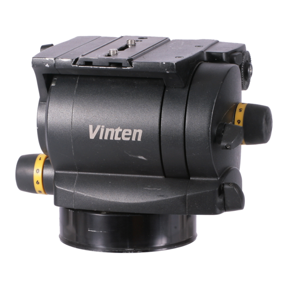
................3 Introduction The Vision 250 pan and tilt head is part of a range designed for broadcast professional, film, corporate and educational use. It is constructed largely in aluminium and magnesium alloys to produce a robust, lightweight unit. -
Page 12: Fig 1.1 Vision 250 Pan And Tilt Head
Contents First Previous Next Previous Page Page Page View (20) (19) (18) (17) (16) (15) (14) (13) (12) (11) (10) Fig 1.1 Vision 250 pan and tilt head... - Page 13 Contents First Previous Next Previous Page Page Page View Friction brakes on each axis allow the head to be locked at any chosen position. The operating levers for both brakes (16)(18) are fitted on the left-hand side of the head. A centre lock allows the head to be locked in the horizontal position.
-
Page 14: Installing The Head On A Tripod
250 Operators Guide, Publication Part No. 3525-8. Installing the head on a tripod The Vision 250 head is supplied with a dual 100/150 mm ball base and is designed for installation on a compatible Vinten Vision tripod. The head is also available with a flat base, with ‘ Quickfix’ and standard four-hole fixing. -
Page 15: Mounting The Camera (Optional Quickfit Adaptor)
Contents First Previous Next Previous Page Page Page View Attach the slide plate to the camera or camera mounting plate under the approximate centre of the camera’s weight using both fixing screws (1). Position the screws as far apart as possible. Set the platform level and engage the centre lock (3). -
Page 16: Balancing The Head
View Balancing the head Balancing the Vision 250 head achieves two objectives. Firstly, when a head is correctly balanced the operator will need a minimum amount of even effort to move the head. Secondly, once balanced, the head and its payload can be set to any tilt position and the head will maintain this position with “hands off”. -
Page 17: Pan And Tilt Brakes
Pan and tilt drag Both the pan and tilt mechanisms incorporate the Vinten thin film (TF) system to ensure smooth movement of the camera about these axes and are fitted with control knobs to adjust the drag setting. - Page 18 Contents First Previous Next Previous Page Page Page View The tilt drag adjustment knob (15) is on the left-hand side of the head, the pan drag knob (12) is on the right-hand side. To increase drag, turn the knob clockwise, towards a higher graduation. To decrease drag, turn the knob anti-clockwise, towards a lower graduation.The whip-pan facility is unaffected by the pan drag setting.
-
Page 19: Special Tools
Bearing support block 3525-908TL Installing tilt drag/tilt brake assembly and right-hand side plate Consumable materials NOTE: Adhesives and lubricants are not supplied by Vinten Broadcast Ltd and should be obtained under local arrangements. ITEM PART No. Grease, Easyrun 50 Z150-081... - Page 20 Contents First Previous Next Previous Page Page Page View ITEM PART No. Loctite 641 Z002-074 Bearing and pin retainer Loctite 5083 Z002-100 Securing PCB Permabond E31 Z002-070 Securing brake pad Silcoset 153 Z002-036 Pin retainer, battery housing 3M VHB surface cleaner Z004-029 Cleaning brake surfaces...
-
Page 21: Cleaning
..............16 General The Vision 250 pan and tilt head is robustly made to high engineering standards and little attention is required to maintain serviceability save regular cleaning. Attention to the following points will ensure a long and useful life with minimum need for repair. -
Page 22: Battery Replacement
All are operated simultaneously by pressing the switch and remain active for approximately 15 seconds. BATTERY TYPE: 9v, 6LR61 (PP3, 6AM6, MN1604, E-BLOCK) Vinten Part No. C550-023 Fig 4.1 Battery Replacement The battery should be replaced yearly or whenever the illumination is considered inadequate. -
Page 23: Adjustments
Contents First Previous Next Previous Page Page Page View To install or replace the battery (Fig 4.1): Prise out the battery cover (3). Pull the battery out of the battery compartment as far as the wiring will allow. Pull the connector off the terminals of the old battery and push it onto the terminals of the new battery (2). -
Page 24: Fig 4.2 Brake Knob Adjustment
Contents First Previous Next Previous Page Page Page View 60° 10.1 11.2 10.2 11.3 45° 10.3 11.4 45° 30° 11.1 11.5 Fig 4.2 Brake Knob Adjustment... -
Page 25: Fig 4.3 Balance Mechanism Digital Display Calibration
Contents First Previous Next Previous Page Page Page View Turn the knob clockwise and ensure that the brake is fully applied before the upper stop is reached. Turn the knob counter-clockwise and ensure the brake is released before the lower stop is reached. Re-adjust the position of the knob if necessary. -
Page 26: Fig 4.4 Converting The Base
Contents First Previous Next Previous Page Page Page View 15.5 Turn the balance knob fully counter-clockwise to its minimum stop. 15.6 Press and release switch (4). 15.7 If the calibration is successful, the display will now show 00. 15.8 If unsuccessful, Er will be displayed. Pressing the switch again, or waiting for 15 seconds, will allow the system to revert to its previous settings. - Page 27 Contents First Previous Next Previous Page Page Page View Section 5 Repair Contents Para General................1 Disassembly Base.
-
Page 28: General
Page Page View General This section details procedures for disassembly and assembly of the Vision 250 pan and tilt head. Reference is made in the procedures to figures in the Illustrated Parts List (page 40). The head is constructed from precision components, many of which are of aluminium or magnesium alloy. -
Page 29: Platform
Contents First Previous Next Previous Page Page Page View Carefully manoeuvre the mechanism housing cover and right-hand side plate off the mechanism housing assembly to the extent allowed by the drag knob wiring. Referring to 6.7, disconnect the drag knob wiring (12). 4.10 Referring to 6.4, ensure shims (2) between load beam (4) and right-hand side plate are retained. -
Page 30: Balance Mechanism
Contents First Previous Next Previous Page Page Page View Balance mechanism WARNING!: Pivot pins (15) are case-hardened and may chip around the screwdriver slot. Use the correct size screwdriver and wear eye protection. To remove the balance mechanism (Fig 6.4): Remove pivot pin (15) securing short link (17) and potentiometer actuator lever (18) in mechanism housing (27). -
Page 31: Pan Brake
Contents First Previous Next Previous Page Page Page View Pan brake To dismantle the pan brake (Fig 6.5): 11.1 Remove the pan brake knob (See “Brake knob adjustment” on page 23.) 11.2 With the head upside-down, remove six screws (16) securing pan brake cover/PCB support (17) to mechanism housing (26). -
Page 32: Tilt Brake
Contents First Previous Next Previous Page Page Page View the tilt drag assembly (1). In this position the tilt brake calliper (27) will align with the cut-out in the tilt brake disc (3) and the outrigger may be pulled off the tilt drag assembly. Pull assembled brake calliper and shaft out of outrigger. -
Page 33: Assembly
Contents First Previous Next Previous Page Page Page View Assembly NOTE: All screws are secured with Loctite 222E unless otherwise stated. Electrical installation Install the electrical installation as follows (Fig 6.7): 16.1 If removed, install the PCB as follows: 16.1.1 Remove all traces of old adhesive from the mechanism housing (2) 16.1.2 Apply a thin bead of Loctite 5083 around the digital display window on the PCB and... -
Page 34: Tilt Drag And Tilt Brake
Contents First Previous Next Previous Page Page Page View 17.5 Install centre lock knob (8) on centre lock shaft (7) and secure with external circlip (9). Lubricate assembled shaft with white bearing grease and install in mechanism housing assembly. 17.6 Apply the self-adhesive cover label (19) to the mechanism housing (21). Tilt drag and tilt brake Assemble the tilt drag and tilt brake as follows (Fig... -
Page 35: Pan Brake
Contents First Previous Next Previous Page Page Page View 19.2 Install shield (20) on shaft of tilt drag assembly (14) 19.3 Position mechanism housing (21) on bearing support block (3525-908TL). Press tilt drag/tilt brake assembly (14) into mechanism housing, ensuring wires are not trapped and that PCB switch engages correctly with ‘O’... -
Page 36: Balance Mechanism
Contents First Previous Next Previous Page Page Page View Balance mechanism WARNING!: Pivot pins (15) are case-hardened and may chip around the screwdriver slot. Use the correct size screwdriver and wear eye protection. NOTE: Lubricate all bearings, shims and pivot points with LM grease. If dismantled, assemble the balance mechanism as follows (Fig 6.4):... -
Page 37: Mechanism Housing Cover/Right-Hand Side Plate
Contents First Previous Next Previous Page Page Page View 23.10 Install balance adjustment stop (7) on balance knob assembly (22). Secure stop in the UP position with screw (26). NOTE: Balance knob assembly (22) has a left-hand thread. 23.11 Keep potentiometer nut (28) butted up to adjustment bracket assembly (8) and screw in balance knob assembly (22) until the front plate is just abutting the mechanism housing. -
Page 38: Platform
Contents First Previous Next Previous Page Page Page View 26.4 Referring to 6.2, secure mechanism cover/right-hand side plate to mechanism housing (21) with two screws (1) and two screws (17). Platform If removed, install the following components on the platform (Fig 6.3): 27.1 Install dowel pin (3) in platform assembly (15). - Page 39 Contents First Previous Next Previous Page Page Page View Install the pan drag knob as follows (Fig 6.5): 32.1 Temporarily install the drag knob boss (10), washer (9) and screw (7) on pan drag shaft (5) and ensure that the drive shaft (5) is turned fully clockwise, to zero. Remove the drag knob boss, washer and screw.
-
Page 40: Introduction
........58 Introduction This parts list is issued for the Vision 250 pan and tilt head, manufactured by Vinten Broadcast Limited, Western Way, Bury St. Edmunds, Suffolk, IP33 3TB, England. -
Page 41: Main Assembly Part Numbers
Main assembly part numbers Ensure that the correct serial and part numbers are quoted when ordering main assemblies. Assembly Part No. Vision 250 pan and tilt head - spherical base 3525-3S Vision 250 pan and tilt head - flat base 3525-3F... -
Page 42: Fig 6.1 Vision 250 Pan And Tilt Head
Contents First Previous Next Previous Page Page Page View V250IP01 Fig 6.1 Vision 250 Pan and Tilt Head... - Page 43 Previous Page Page Page View Fig 6.1 Vision 250 Pan and Tilt Head Item Part Nomenclature 3525-3S Vision 250 pan and tilt head - spherical base, comprising: 3525-11 Main assembly (Fig 6.2) 3219-69 Telescopic pan bar assembly (Fig 6.8) 3525-900SP*...
-
Page 44: Fig 6.2 Vision 250 Pan And Tilt Head - Main Assembly
Contents First Previous Next Previous Page Page Page View V250IP06 Fig 6.2 Vision 250 Pan and Tilt Head - Main Assembly... - Page 45 Contents First Previous Next Previous Page Page Page View Fig 6.2 Vision 250 Pan and Tilt Head - Main Assembly Item Part Nomenclature M005-721 Screw, skt cap hd, M4 x 25 mm lg 3525-203 Mechanism housing cover N600-010 Steel ball, 1/8 in. dia...
-
Page 46: Fig 6.3 Vision 250 Pan And Tilt Head - Platform
Contents First Previous Next Previous Page Page Page View V250IP02 Fig 6.3 Vision 250 Pan and Tilt Head - Platform... - Page 47 Contents First Previous Next Previous Page Page Page View Fig 6.3 Vision 250 Pan and Tilt Head - Platform Item Part Nomenclature 3364-900SP* Platform slide, including: 3170-202 Screw, large M801-048 Pin, dowel, 5 mm dia x 12 mm lg 3525-263 Serial No.
-
Page 48: Fig 6.4 Vision 250 Pan And Tilt Head - Balance Mechanism
Contents First Previous Next Previous Page Page Page View V250IP03 Fig 6.4 Vision 250 Pan and Tilt Head - Balance Mechanism... - Page 49 Contents First Previous Next Previous Page Page Page View Fig 6.4 Vision 250 Pan and Tilt Head - Balance Mechanism Item Part Nomenclature 3525-13* Tilt drag assembly (Fig 6.6) 3322-229 Actuator shim N500-004 Bearing, needle roller 3525-231 Load beam M005-706...
-
Page 50: Fig 6.5 Vision 250 Pan And Tilt Head - Pan Drag And Pan Brake
Contents First Previous Next Previous Page Page Page View V250IP04 Fig 6.5 Vision 250 Pan and Tilt Head - Pan Drag and Pan Brake... - Page 51 Previous Next Previous Page Page Page View Fig 6.5 Vision 250 Pan and Tilt Head - Pan Drag and Pan Brake Item Part Nomenclature M006-704 Screw, skt cap hd, M5 x 16 mm lg M006-703 Screw, skt cap hd, M5 x 12 mm lg...
-
Page 52: Fig 6.6 Vision 250 Pan And Tilt Head - Tilt Drag And Tilt Brake
Contents First Previous Next Previous Page Page Page View V250IP05 Fig 6.6 Vision 250 Pan and Tilt Head - Tilt Drag and Tilt Brake... - Page 53 First Previous Next Previous Page Page Page View Fig 6.6 Vision 250 Pan and Tilt Head - Tilt Drag and Tilt Brake Item Part Nomenclature 3525-13 Tilt drag assembly, including: M806-042 Pin, Spirol, 2.5 mm dia x 8 mm lg...
-
Page 54: Fig 6.7 Vision 250 Pan And Tilt Head - Electrical Installation
Contents First Previous Next Previous Page Page Page View V250IP07 Fig 6.7 Vision 250 Pan and Tilt Head - Electrical Installation... - Page 55 Contents First Previous Next Previous Page Page Page View Fig 6.7 Vision 250 Pan and Tilt Head - Electrical Installation Item Part Nomenclature 3525-204 Outrigger (Fig 6.2) 3525-902SP* Mechanism housing (Fig 6.2) 3525-203 Mechanism housing cover (Fig 6.2) 3431-267 LED lens...
-
Page 56: Fig 6.8 Vision 250 Pan And Tilt Head - Pan Bar
Contents First Previous Next Previous Page Page Page View V100IP07 Fig 6.8 Vision 250 Pan and Tilt Head - Pan Bar... - Page 57 Contents First Previous Next Previous Page Page Page View Fig 6.8 Vision 250 Pan and Tilt Head - Pan Bar Item Part Nomenclature M006-113 Screw, csk Pozi hd, M5 x 12 mm lg M606-001 Washer, nylon, Skiffy 07-3-5 3219-70 Pan bar clamp assembly, comprising:...
-
Page 58: Fig 6.9 Vision 250 Pan And Tilt Head - Composite Spare Parts
Contents First Previous Next Previous Page Page Page View Fig 6.9 Vision 250 Pan and Tilt Head - Composite Spare Parts Part No. Nomenclature 3364-900SP Platform slide assembly, comprising: 3364-210 Platform slide Q001-093 ‘O’ ring, 200-044-44 3170-202 Screw, large 3431-900SP... - Page 59 Contents First Previous Next Previous Page Page Page View Fig 6.9 Vision 250 Pan and Tilt Head - Composite Spare Parts (Cont) Part No. Nomenclature M850-011 Wire thread insert, M10 3525-902SP Mechanism housing assembly, comprising: 3525-201 Mechanism housing 3525-256 Level bubble support...
- Page 60 Contents First Previous Previous Page Page View Fig 6.9 Vision 250 Pan and Tilt Head - Composite Spare Parts (Cont) Part No. Nomenclature 3525-909SP Battery connector 3525-910SP Tilt LED 3525-911SP Pan LED...
Need help?
Do you have a question about the Vision 250 and is the answer not in the manual?
Questions and answers