Table of Contents
Advertisement
Quick Links
Advertisement
Table of Contents
Troubleshooting

Related Manuals for Mindray uMEC10


Summary of Contents for Mindray uMEC10
- Page 1 Patient Monitor Operator’s Manual...
- Page 3 © Copyright 2016 Shenzhen Mindray Bio-Medical Electronics Co., Ltd. All rights reserved. For this Operator’s Manual, the issue date is 2016-1. WARNING Federal Law (USA) restricts this device to sale by or on the order of a physician.
- Page 4 , and are the registered trademarks or trademarks owned by Mindray in China and other countries. All other trademarks that appear in this manual are used only for editorial purposes without the intention of improperly using them. They are the property of their respective owners.
- Page 5 Party Contents of this manual are subject to changes without prior notice. All information contained in this manual is believed to be correct. Mindray shall not be liable for errors contained herein nor for incidental or consequential damages in connection with the furnishing, performance, or use of this manual.
- Page 6 OR FITNESS FOR ANY PARTICULAR PURPOSE. Exemptions Mindray's obligation or liability under this warranty does not include any transportation or other charges or liability for direct, indirect or consequential damages or delay resulting from the improper use or application of the product or the use of parts or accessories not approved by Mindray or repairs by people other than Mindray authorized personnel.
- Page 7 Customer Service Department Manufacturer: Shenzhen Mindray Bio-Medical Electronics Co., Ltd. Mindray Building, Keji 12th Road South, Hi-tech industrial Address: park, Nanshan,Shenzhen 518057,P.R.China www.mindray.com Website: E-mail Address: service@mindray.com Tel: +86 755 81888998 Fax: +86 755 26582680 EC-Representative: Shanghai International Holding Corp. GmbH(Europe)
- Page 8 Preface Manual Purpose This manual contains the instructions necessary to operate the product safely and in accordance with its function and intended use. Observance of this manual is a prerequisite for proper product performance and correct operation and ensures patient and operator safety.
-
Page 9: Table Of Contents
2.1.1 Intended Use....................... 2-1 2.1.2 Applied Parts ...................... 2-1 2.2 Front View ........................2-2 2.3 Side View ........................2-4 2.3.1 uMEC10 ......................2-4 2.3.2 uMEC12/uMEC15 ..................... 2-5 2.4 Rear View ........................2-6 2.5 Display Screen ......................2-7 2.6 QuickKeys ........................2-9 3 Basic Operations ...................... - Page 10 3.10.2 Accessing the Parameters Menu ..............3-11 3.11 Operating Modes ...................... 3-11 3.11.1 Monitoring Mode .................... 3-11 3.11.2 Night Mode ..................... 3-11 3.11.3 Privacy Mode ....................3-12 3.11.4 Demo Mode ....................3-13 3.11.5 Standby Mode ....................3-13 4 Managing Patients ......................4-1 4.1 Discharging a Patient ....................
- Page 11 6.2.2 Setting Minitrends ....................6-3 6.3 Viewing OxyCRG ....................... 6-3 6.4 Viewing Other Patients ....................6-4 6.4.1 Care Group ......................6-4 6.4.2 Viewing the Care Group Overview Bar ............. 6-5 6.4.3 Understanding the View Other Patient Window ..........6-5 6.5 Understanding the Big Numerics Screen ..............6-7 7 Alarms ..........................
- Page 12 8.3.1 Preparing the Patient and Placing the Electrodes ..........8-2 8.3.2 Choosing AHA or IEC Lead Placement ............. 8-2 8.3.3 ECG Lead Placements ..................8-3 8.3.4 Checking Paced Status ..................8-5 8.4 Understanding the ECG Display ................. 8-6 8.5 Changing ECG Settings ....................8-7 8.5.1 Accessing ECG Menus ..................
- Page 13 8.10.2 Automatic ECG Relearning ................8-24 8.11 12-Lead ECG Monitoring (for uMEC12/uMEC15) ..........8-25 8.11.1 Entering the 12-lead ECG Monitoring Screen ..........8-25 8.11.2 Extending the Rhythm Lead Waveform Area ..........8-26 8.12 Troubleshooting ...................... 8-26 9 Monitoring Respiration (Resp) ..................9-1 9.1 Introduction .........................
- Page 14 12 Monitoring NIBP ......................12-1 12.1 Introduction ......................12-1 12.2 Safety ........................12-2 12.3 Measurement Limitations ..................12-2 12.4 Measurement Methods .................... 12-3 12.5 Setting Up the NIBP Measurement ................. 12-3 12.5.1 Preparing the Patient ..................12-3 12.5.2 Preparing to Measure NIBP ................12-3 12.5.3 Starting and Stopping Measurements .............
- Page 15 15.1 Introduction ......................15-1 15.2 Understanding the C.O. Display ................15-1 15.3 Influencing Factors ....................15-2 15.4 Setting Up the C.O. Measurement ................15-2 15.5 Measuring the Blood Temperature ................15-6 15.6 Changing C.O. Settings ................... 15-6 15.6.1 Setting the Temperature Unit ................. 15-6 15.6.2 Setting Alarm Properties ................
- Page 16 19.2.1 Performing Calculations ................. 19-2 19.2.2 Selecting the Proper Drug Unit ..............19-2 19.2.3 Titration Table ....................19-3 19.2.4 Drug Calculation Formulas ................19-3 19.3 Hemodynamic Calculations ..................19-4 19.3.1 Performing Calculations ................. 19-4 19.3.2 Entered Parameters ..................19-4 19.3.3 Calculated Parameters and Formulas ............. 19-5 19.4 Understanding the Review Window ................
- Page 17 22.3.1 Data Export System ..................22-1 22.3.2 Transferring Data by Different Means ............22-2 22.4 Nurse Call ....................... 22-3 22.5 Network Connection ....................22-4 22.5.1 Selecting a Network Type ................22-4 22.5.2 Setting the Wired Network ................22-4 22.5.3 Setting the Wireless Network ................. 22-4 22.5.4 Testing the Wireless Network .................
- Page 18 26.6 C.O. Accessories (for uMEC12/uMEC15) .............. 26-7 26.7 CO Accessories (for uMEC12/uMEC15) .............. 26-8 26.8 Others ........................26-9 A Product Specifications ....................A-1 A.1 Monitor Safety Specifications ................... A-1 A.2 Power Supply Specifications ..................A-2 A.3 Physical Specifications ....................A-3 A.4 Hardware Specifications ...................
-
Page 19: Safety
Safety 1.1 Safety Information WARNING Indicates a potential hazard or unsafe practice that, if not avoided, could result in death or serious injury. CAUTION Indicates a potential hazard or unsafe practice that, if not avoided, could result in minor personal injury or product/property damage. NOTE Provides application tips or other useful information to ensure that you get the most from your product. -
Page 20: Warnings
1.1.1 Warnings WARNING This equipment is used to one patient at a time. Before putting the system into operation, the operator must verify that the equipment, connecting cables and accessories are in correct working order and operating condition. To avoid risk of electric shock, this equipment must only be connected to a supply mains with protective earth.If the installation does not provide for a protective earth conductor, disconnect it from the power line and operate it on battery power, if possible. -
Page 21: Cautions
1.1.2 Cautions CAUTION To ensure patient safety, use only parts and accessories specified in this manual. At the end of its service life, the equipment, as well as its accessories, must be disposed of in compliance with the guidelines regulating the disposal of such products. -
Page 22: Equipment Symbols
1.2 Equipment Symbols NOTE Some symbols may not appear on your equipment. Refer to instruction General warning sign manual/booklet Power ON/OFF (for a part Battery indicator of the equipment) Alternating current ALARM PAUSED Alarm reset Graphical recorder Freeze/unfreeze waveforms Main menu NIBP start/stop key Output Equipotentiality... - Page 23 DEFIBRILLATION-PROOF TYPE BF APPLIED PART The following definition of the WEEE label applies to EU member states only. This symbol indicates that this product should not be treated as household waste. By ensuring that this product is disposed of correctly, you will help prevent bringing potential negative consequences to the environment and human health.
- Page 24 FOR YOUR NOTES...
-
Page 25: The Basics
The Basics 2.1 Monitor Description 2.1.1 Intended Use The uMEC series patient monitors are intended to be used for monitoring, displaying, reviewing, storing and transferring of multiple physiological parameters including ECG, heart rate (HR), respiration (Resp), temperature (Temp), pulse oxygen saturation (SpO pulse rate (PR), non-invasive blood pressure (NIBP), invasive blood pressure (IBP), cardiac output (C.O.) and carbon dioxide (CO The monitors are to be used in healthcare facilities by clinical professionals or under their... -
Page 26: Front View
2.2 Front View (10) (11) (1) Display Screen (2) Alarm lamp When a physiological alarm or technical alarm occurs, this lamp will flash as defined below. ‹ High level alarms: the lamp quickly flashes red. ‹ Medium level alarms: the lamp slowly flashes yellow. ‹... - Page 27 If no menu is displayed on the screen, pressing it will enter the main menu. If there is a menu displayed on the screen, pressing it will close that menu. Battery LED ‹ On: when the battery is installed and the AC source is connected. ‹...
-
Page 28: Side View
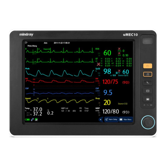
2.3 Side View 2.3.1 uMEC10 (1) Recorder (2) Power On/Off switch ‹ Pressing this switch turns the patient monitor on. ‹ When the monitor is on, pressing and holding this switch turns the monitor off. (3) Connector for Temp probe... -
Page 29: Umec12/Umec15
2.3.2 uMEC12/uMEC15 (10) -
Page 30: Rear View
(1) Recorder (2) Slot for CO watertrap (3) Connector for C.O. cable (4) CO gas outlet (5) Connector for IBP cable (6) Power On/Off switch ‹ Pressing this switch turns the patient monitor on. ‹ When the monitor is on, pressing and holding this switch turns the monitor off. (7) Connector for Temp probe (8) Connector for SpO cable... -
Page 31: Display Screen
(3) USB Connector It connects such devices as the USB mice, USB keyboard, barcode scanner, etc. (4) Network Connector It is a standard RJ45 connector which connects the patient monitor to CMS or other patient monitor for remote view. It also connects the patient monitor to PC for system upgrade. - Page 32 (1) Patient Information Area This area shows the patient information such as department, bed number, patient name and patient category, indicates that no patient is admitted or the patient information is incomplete. If no patient is admitted, selecting this area will enter the [Patient Setup] menu.
-
Page 33: Quickkeys
This area shows the current configuration name, prompt messages, network status icons, battery status icons, etc. For details about battery status symbols, refer to the 23 Batteries. ‹ indicates patient monitor is connected to a wired network successfully. ‹ indicates the patient monitor has failed to connect a wired network. ‹... - Page 34 Symbol Label Function Zero IBP Starts IBP zero calibration. Alarm Reset Resets the alarm system. Alarm Pause Pauses or restores alarms. Screens Changes screen. Patient Setup Enters the [Patient Setup] menu. Minitrends Has a split-screen view of minitrends Volume Setup Enters the [Volume Setup] menu.
- Page 35 You can also select your desired QuickKeys to display on the screen. Select [Main Menu] [Maintenance >>] [Manage Configuration >>] enter the required password [Ok]. Select [Edit Config.>>] [Edit] [Screen Setup >>]. In the [Select QuickKeys] screen, select your desired QuickKeys and arrange them. 2-11...
- Page 36 FOR YOUR NOTES 2-12...
-
Page 37: Basic Operations
Basic Operations 3.1 Installation WARNING The equipment shall be installed by personnel authorized by us. The software copyright of the equipment is solely owned by us. No organization or individual shall resort to juggling, copying, or exchanging it or to any other infringement on it in any form or by any means without due permission. -
Page 38: Environmental Requirements
WARNING When disposing of the packaging material, be sure to observe the applicable waste control regulations and keep it out of children’s reach. The equipment might be contaminated during storage and transport. Before use, please verify whether the packages are intact, especially the packages of single use accessories. -
Page 39: Getting Started
3.2 Getting Started 3.2.1 Turning Power On Once the patient monitor is installed, you can get ready for monitoring: Before you start to make measurements, check the patient monitor for any mechanical damage and make sure that all external cables, plug-ins and accessories are properly connected. -
Page 40: Disconnecting From Power
3.3 Disconnecting from Power To disconnect the patient monitor from the AC power source, follow this procedure: Confirm that the patient monitoring is finished. Disconnect patient cables and sensors from the patient. Make sure to save or clear the patient monitoring data as required. Press and hold the power on/off switch. -
Page 41: Using The Touchscreen
3.5 Using the Touchscreen Select screen items by pressing them directly on the patient monitor’s screen. You can enable or disable touchscreen operation by pressing and holding the [Main Menu] QuickKey for 3 seconds. A padlock symbol is displayed if touchscreen operation is disabled. 3.6 Setting the Screen You can enter the [Screen Setup] window as shown below by selecting [Main Menu] [Screen Setup] [Screen Layout >>]. -
Page 42: Using The On-Screen Keyboard
If no corresponding parameter or waveform is displayed on the monitor screen, you should perform the following inspections: „ Check the connection of the lead, cable, or sensor. „ Enter the [Screen Setup] window for the desired display configuration. „ Check that the parameter is switched on in [Parameters Switch] window. -
Page 43: Using The Main Menu
3.8 Using the Main Menu To enter the main menu, select [Main Menu] QuickKey or the hardkey on the monitor’s front. Most of monitor operations and settings can be performed through the main menu. Other menus are similar to the main menu and contain the following parts: (1) Heading: gives a sum-up for the current menu. -
Page 44: Changing General Settings
3.9 Changing General Settings This chapter covers only general settings such as language, brightness, date and time, etc. Measurement settings and other settings can be referred to in respective sections. 3.9.1 Setting up a Monitor In situations where you install a patient monitor or change the patient monitor’s application site, you need to setup the patient monitor as follows: Select [Main Menu] [Maintenance >>] [User Maintenance >>] enter the required password. -
Page 45: Showing/Hiding The Help
3.9.4 Showing/Hiding the Help The patient monitor provides online help information. The user can display or hide the help as required. Select [Main Menu] [Screen Setup >>]. Select [Help] and toggle between [On] and [Off]. 3.9.5 Setting the Date and Time Select [Main Menu] [Maintenance >>] [System Time >>]. -
Page 46: Setting Parameters
Key Volume When you press the navigation knob or the touchscreen, or the hardkeys on the panel, the patient monitor prompts you by making a sound of the key volume you have set. Select the [Volume Setup] QuickKey, or [Main Menu] [Screen Setup >>]. Select [Key Volume] and then select the appropriate volume. -
Page 47: Accessing The Parameters Menu
When a parameter is switched off, its corresponding parameter module stops working, and its parameter value and waveform are not shown on the monitor display. NOTE ECG is always selected, and you cannot switch it off. 3.10.2 Accessing the Parameters Menu Select [Parameters >>] from the main menu or select corresponding parameter area or waveform area to access a parameter setup menu. -
Page 48: Privacy Mode
WARNING Before entering night mode, confirm the settings of brightness, alarm volume, QRS volume, and key volume. Pay attention to the potential risk when the setting value is a bit low. 3.11.3 Privacy Mode Privacy mode is only available when a patient who is admitted at a patient monitor is also monitored by the central station. -
Page 49: Demo Mode
3.11.4 Demo Mode In Demo mode, the monitor can demonstrate its major functions when patient or patient simulator is not connected. The Demo mode is password protected. To enter the Demo mode: Select [Main Menu] [Maintenance >>]. Select [Demo >>]. Enter the required password and then select [Ok]. To exit the Demo mode, select [Main Menu] [Maintenance >>] [Exit Demo]. - Page 50 FOR YOUR NOTES 3-14...
-
Page 51: Managing Patients
Managing Patients 4.1 Discharging a Patient Before monitoring a new patient, discharge the previous patient. After the patient is discharged, all patient data, including patient information, trend data, and physiological alarm information is deleted from the monitor. The technical alarms are reset, and monitor settings return to their defaults. -
Page 52: Manually Discharging A Patient
4.1.2 Manually Discharging a Patient To manually discharge a patient: Select the [Patient Setup] QuickKey, or [Main Menu] [Patient Setup >>]. Select [Discharge Patient]. In the popup menu, you can either: ‹ Directly select [Ok] to discharge the current patient, or ‹... -
Page 53: Manually Admitting A Patient
4.2.2 Manually Admitting a Patient To manually admit a patient: Select the [Patient Setup] QuickKey, or [Main Menu] [Patient Setup >>]. Select [Admit Patient] or [Quick Admit]. ‹ [Admit Patient] to fully admit a patient so that you can clearly identify your patient, on recordings, reports and networking devices. -
Page 54: Associating Patient Information
Select a patient and then click [Import]. Then the monitor will update the information of corresponding patient. Select to exit the [Obtain Patient Information] menu. NOTE The option [Obtain Patient Information] is available in the [Patient Setup] menu only when [ADT Query] is set to [On]. When obtaining patient information from HIS, the monitor only update patient inforamtion. -
Page 55: Transferring Data From The Monitor To A Usb Drive
WARNING Do not discharge a patient before the patient is successfully transferred. After a patient is successfully transferred, check if the patient settings (especially patient category, paced status and alarm limits settings, etc) on the monitor are appropriate for this patient. NOTE The system automatically switches on the HR alarm and lethal arrhythmia alarm after transferring the patient data. -
Page 56: Transferring Data From The Usb Drive To Monitor
4.4.3 Transferring Data from the USB Drive to Monitor Connect the USB drive to the destination monitor. In the popup menu, you can: ‹ Select [Transfer] to transfer the patient data to the monitor, or ‹ Select [Cancel Transfer] to cancel the operation of transferring patient data. ‹... -
Page 57: Connecting To A Central Monitoring System
4.5 Connecting to a Central Monitoring System If your patient monitor is connected to a central monitoring system (CMS): „ All patient information, measurement data and settings on the patient monitor can be transferred to the CMS. „ All patient information, measurement data and settings can be displayed simultaneously on the patient monitor and CMS. - Page 58 FOR YOUR NOTES...
-
Page 59: Managing Configurations
Managing Configurations 5.1 Introduction When performing continuous monitoring on a patient, the clinical professional often needs to adjust the monitor’s settings according to the patient’s condition. The collection of all these settings is called a configuration. Allowing you to configure the monitor more efficiently, the monitor offers different sets of configuration to suit different patient categories. -
Page 60: Entering The [Manage Configuration] Menu
5.2 Entering the [Manage Configuration] Menu Press the hardkey on the monitor’s front to enter the main menu. Select [Maintenance >>] [Manage Configuration >>]. Enter the required password and then select [Ok]. 5.3 Setting Default Configuration The monitor will load the pre-set default configuration in the following cases. „... -
Page 61: Saving Current Settings
When you select [Load Specified Config.], the configuration (adult, pediatric or neonate) to be restored is subject to the patient category. This configuration can be either factory configuration or saved user configuration. Take adult as an example, select [Default Adu Config.] and toggle between [Defaults] or user configuration(s). -
Page 62: Deleting A Configuration
The popup menu shows the existing configurations on the monitor. Selecting [Config. on USB drive >>] will show the existing configurations on the USB drive. Select the desired configuration and then select the [Edit] button. The following menu appears. Select [Alarm Setup >>], [Screen Setup >>] or [Parameter >>] to enter the corresponding menu in which settings can be changed. -
Page 63: Transferring A Configuration
5.7 Transferring a Configuration When installing several monitors with identical user configuration it is not necessary to set each unit separately. An USB drive may be used to transfer the configuration from monitor to monitor. To export the current monitor’s configuration: Connect the USB drive to the monitor’s USB port. -
Page 64: Restoring The Latest Configuration Automatically
5.9 Restoring the Latest Configuration Automatically During operation, you may make changes to some settings. However, these changes may not be saved as user configuration. To prevent the changes from losing in case of a sudden power failure, the patient monitor stores the configuration in real time. The saved configuration is the latest configuration. -
Page 65: User Screens
User Screens 6.1 Tailoring Your Screens You can tailor your patient monitor’s screens by setting: „ Wave line size „ The color in which each measurement’s numerics and waveform are displayed „ The parameter to be monitored. Changing some settings may be hazardous. Therefore, those setting are password-protected and can be modified by authorized personnel only. -
Page 66: Viewing Minitrends
„ You can switch on or off the connected parameter modules in the [Parameters Switch] window. If a parameter module is switched off, parameter values and waveforms will not display on the screen. 6.2 Viewing Minitrends 6.2.1 Having a Split-Screen View of Minitrends You can split the normal screen so that one part of the screen, on the left hand side, continuously shows graphic minitrends beside waveforms as shown in the figure below. -
Page 67: Setting Minitrends
The split-screen view provides minitrends for multiple parameters. In each field, the label and scale are respectively displayed at the top and left. The time is displayed at the bottom of the minitrends shown view. 6.2.2 Setting Minitrends Select the minitrends area. From the pop-up [Minitrend Setup] menu, you can: „... -
Page 68: Viewing Other Patients
The split-screen view covers the lower part of the waveform area and shows HR trend, SpO trend, RR trend, and a compressed wave (Resp wave or CO wave). At the bottom, there are controls: (1) Trend length list box In the trend length list box, you can select [1 min], [2 min], [4 min], or [8 min]. (2) Setup Select the [Setup] button to enter the [Setup] menu, in which you can select the parameters for display, the time length to be saved before and after an event, and the... -
Page 69: Viewing The Care Group Overview Bar
6.4.2 Viewing the Care Group Overview Bar The Care Group overview bar locates at the bottom of the [View Other Patient] window. In the overview bar, the department and bed label for any Care Group beds are displayed. The color in which a Care Group bed appears matches its status: „... - Page 70 The [View Other Patient] window covers the lower part of the waveform area and consists (1) Information Area: shows the patient information (including department, bed number, patient name, etc.), network status symbol. (2) View Area: shows physiological waveforms and parameters. You can switch a waveform area to a parameter area by selecting your desired waveform area and then selecting [Switch to Parameter Area], or switch a parameter area to a waveform area by selecting your desired parameter area and then selecting [Switch to Waveform...
-
Page 71: Understanding The Big Numerics Screen
6.5 Understanding the Big Numerics Screen To enter the big numerics screen: Select the [Screens] QuickKey, or [Main Menu] [Screen Setup >>] [Screen Layout >>] [Choose Screen]. Select [Big Numerics] You can select your desired parameters to display in this screen: select the [Screens] QuickKey [Big Numerics Screen Setup] and then select the parameters you want. - Page 72 FOR YOUR NOTES...
-
Page 73: Alarms
Alarms Alarms, triggered by a vital sign that appears abnormal or by technical problems of the patient monitor, are indicated to the user by visual and audible alarm indications. WARNING A potential hazard can exist if different alarm presets are used for the same or similar equipment in any single area, e.g. -
Page 74: Alarm Levels
7.2 Alarm Levels By severity, the patient monitor’s alarms can be classified into three categories: high level, medium level and low level. Physiological alarms Technical alarms Indicate that your patient is in a Indicate a severe device malfunction or an life threatening situation, such improper operation, which could make it possible High... -
Page 75: Alarm Message
7.3.2 Alarm Message When an alarm occurs, an alarm message will appear in the technical or physiological alarm area. For physiological alarms, the asterisk symbols (*) before the alarm message match the alarm level as follows: „ High level alarms: „... -
Page 76: Alarm Status Symbols
„ Mode 2: ‹ High level alarms: high-pitched triple beep. ‹ Medium level alarms: double beep. ‹ Low level alarms: low-pitched single beep. NOTE When multiple alarms of different levels occur simultaneously, the patient monitor will select the alarm of the highest level, light the alarm lamp and give alarm sounds accordingly, while all the alarm messages are displayed circularly on the screen. -
Page 77: Alarm Tone Configuration
7.4 Alarm Tone Configuration 7.4.1 Setting the Minimum Alarm Volume Select [Main Menu] [Maintenance >>] [User Maintenance >>] enter the required password. Select [Alarm Setup >>] to enter the [Alarm Setup] menu. Select [Minimum Alarm Volume] and toggle between 0 and 10. The minimum alarm volume refers to the minimum value you can set for the alarm volume, which is not affected by user or factory default configurations. -
Page 78: Changing The Alarm Tone Pattern
„ Mode 2: ‹ Interval between high level alarm tones: 1 s. ‹ Interval between medium level alarm tones: 5 s. ‹ Interval between low level alarm tones: 20 s. If you choose the ISO pattern, you can change the interval between alarm tones. To change the interval between alarm tones: Select [Main Menu] [Maintenance >>] [User Maintenance >>] enter the required password. -
Page 79: Setting The Reminder Tones
7.4.5 Setting the Reminder Tones When the alarm volume is set to zero, or the alarm tone is reset or switched off, the patient monitor issues a periodical reminder tone. To set the reminder tones: Select [Main Menu] [Maintenance >>] [User Maintenance >>] enter the required password. -
Page 80: Setting Alarm Properties For All Parameters
Please refer to 8 Monitoring ECG for how to change ST alarm settings, how to change arrhythmia alarm settings and how to set the threshold for some arrhythmia alarms. 7.5.1 Setting Alarm Properties for All Parameters In the main menu, select [Alarm Setup >>] [Parameters]. You can review and set alarm limits, alarm switches, alarm level and alarm recordings for all parameters. -
Page 81: Adjusting Alarm Limits Automatically
7.5.2 Adjusting Alarm Limits Automatically The monitor can automatically adjust alarm limits according to the measured vital signs, using the auto limits function. When auto limits are selected, the monitor calculates safe auto limits based on the latest measured values. To get accurate auto alarm limits, you need to collect a set of measured vital signs as a baseline. - Page 82 Low alarm limit High alarm limit Auto alarm limits Module Parameter Adult/ Adult/ range Neonate Neonate pediatric pediatric (Mean – 15) (Mean + 15) Adult: 30 to 230 (Mean × 0.68 or 35mmHg (Mean × 0.86 or 95 mmHg NIBP-M Pediatric: 30 to 165 + 8) mmHg (whichever...
- Page 83 Low alarm limit High alarm limit Auto alarm limits Module Parameter Adult/ Adult/ range Neonate Neonate pediatric pediatric 0 to 0 to 0 to 32mmHg: 0 to 32mmHg: 32mmHg: 32mmHg: remains the remains the remains the remains the same same same same 32 to...
-
Page 84: Setting Alarm Delay Time
7.5.3 Setting Alarm Delay Time You can set the alarm delay time for over-limit alarms of continuously measured parameters. If the alarm-triggered condition disappears within the delay time, the patient monitor will not give the alarm. You can set the [Alarm Delay] in the [Others] window of [Alarm Setup] menu. -
Page 85: Setting Recording Length
7.5.5 Setting Recording Length You can change the length of the recorded waveforms. In the [Others] window of the [Alarm Setup] menu, select [Recording Length] and toggle between [8 s], [16 s] and [32s]: „ [8 s]: 4 seconds respectively before and after the alarm or manual event trigger moment. -
Page 86: Switching Off All Alarms
You can also temporarily prolong the alarm pause time after the monitor entersthe alarm paused status: Select [Main Menu] [Maintenance >>] [User Maintenance >>] enter the required password [Alarm Setup >>]. In the [Alarm Setup] menu, set the [Max. Alarm Pause 15min] to [Enable]. In the physiological alarm area, select a proper time in the [Alarm Pause Time] menu. -
Page 87: Resetting Alarms
7.8 Resetting Alarms By selecting the QuickKey, you can reset the alarm system to acknowledging the on-going alarms and enable the alarm system to respond to a subsequent alarm condition. For physiological alarms, except the NIBP-related alarms, when the alarm system is reset: „... -
Page 88: Latching Alarms
7.9 Latching Alarms The alarm latching setting for your patient monitor defines how the indicators of the physiological alarms behave when you do not acknowledge them: „ If you do not “latch” the physiological alarms, their alarm indications disappear when the alarm condition ends. -
Page 89: Testing Alarms
7.10 Testing Alarms When the monitor starts up, a selftest is performed. In this case the alarm lamp is lit in yellow and red respectively, and the system gives a beep. This indicates that the visible and audible alarm indicators are functioning correctly. For further testing of individual measurement alarms, perform the measurement on yourself (for example SpO or CO... -
Page 90: Resetting Care Group Alarms
7.11.3 Resetting Care Group Alarms You can reset the alarms presented on the viewed bed by pressing the [Alarm Reset] from the current monitor’s [View Other Patient] window. To enable this function: Select [Main Menu] [Maintenance>>] [User Maintenance>>] enter the required password [Alarm Setup>>]. -
Page 91: Monitoring Ecg
The electrocardiogram (ECG) measures the electrical activity of the heart and displays it on the patient monitor as a waveform and a numeric. For uMEC10, ECG monitoring provides 3-, 5-lead ECG monitoring, ST-segment analysis and arrhythmia analysis. For uMEC12 and uMEC15, ECG monitoring provides 3-, 5- and 12-lead ECG monitoring, ST-segment analysis and arrhythmia analysis. -
Page 92: Preparing To Monitor Ecg
NOTE After defibrillation, the screen display recovers within 10 seconds if the correct electrodes are used and applied in accordance with the manufacturer’s instructions for use. 8.3 Preparing to Monitor ECG 8.3.1 Preparing the Patient and Placing the Electrodes Prepare the patient’s skin. Proper skin preparation is necessary for good signal quality at the electrode, as the skin is a poor conductor of electricity. -
Page 93: Ecg Lead Placements
8.3.3 ECG Lead Placements The electrode placement illustrations in this chapter adopt the AHA standard. 3-Leadwire Electrode Placement Following is an electrode configuration when using 3 leadwires: „ RA placement: directly below the clavicle and near the right shoulder. „ LA placement: directly below the clavicle and near the left shoulder. - Page 94 The chest (V) electrode can be placed on one of the following positions: „ V1 placement: on the fourth intercostal space at the right sternal border. „ V2 placement: on the fourth intercostal space at the left sternal border. „ V3 placement: midway between the V2 and V4 electrode positions.
-
Page 95: Checking Paced Status
Lead Placement for Surgical Patients The surgical site should be taken into consideration when placing electrodes on a surgical patient. e.g. for open-chest surgery, the chest electrodes can be placed on the lateral chest or back. To reduce artifacts and interference from electrosurgical units, you can place the limb electrodes close to the shoulders and lower abdomen and the chest electrodes on the left side of the mid-chest. -
Page 96: Understanding The Ecg Display
WARNING For paced patients, you must set [Paced] to [Yes]. If it is incorrectly set to [No], the patient monitor could mistake a pace pulse for a QRS and fail to alarm when the ECG signal is too weak. Do not rely entirely on rate meter alarms when monitoring patients with pacemakers. -
Page 97: Changing Ecg Settings
For 12-lead ECG display screen, refer to 8.11 12-Lead ECG Monitoring (for uMEC12/uMEC15). 8.5 Changing ECG Settings 8.5.1 Accessing ECG Menus By selecting the ECG parameter window or waveform area, you can access the [ECG Setup] menu. 8.5.2 Choosing the Alarm Source In most cases the HR and PR numerics are identical. -
Page 98: Changing The Ecg Filter Settings
When monitoring with a 12-lead set, you can also choose the screen type as [ECG 12-Lead Full-Screen]. When the screen type is set to [Normal Screen], cascaded ECG waveforms can be displayed. To cascade ECG waveforms: Select the [Screens] Quickkey [Screen Setup]. Select [ECG1 Casc.] in the second row. -
Page 99: Changing The Pacer Reject Settings
Set notch frequency according to the electric power frequency of your country. Follow this procedure: When [Notch Filter] is set on, select [Main Menu] [Maintenance >>] [User Maintenance >>] enter the required password. Select [Others >>] [Notch Freq.] and then select [50Hz] or [60Hz] according to the power line frequency. -
Page 100: Enabling Smart Lead Off
8.5.9 Enabling Smart Lead Off When the smart lead off function is set on and there is a “lead off” in the lead that has an ECG waveform in filter mode and notch status, if another lead is available, this available lead automatically becomes that lead. -
Page 101: About St Monitoring
8.6 About ST Monitoring „ ST segment analysis calculates ST segment elevations and depressions for individual leads and then displays them as numerics in the ST1 and ST2 areas. „ A positive value indicates ST segment elevation; a negative value indicates ST segment depression. -
Page 102: Understanding The St Display
NOTE When the filter mode is switched to [Diagnostic], the notch filter automatically switches to [Off]. In this case, you can still set the notch filter to [On] manually. When the filter mode is [Monitor], [Surgery] or [ST], the notch filter is fixed to [On], and can not be changed. -
Page 103: Saving The Current St Segment As Reference
Select the ST parameter window or ST segment area and you can enter the [ST Analysis] menu. 8.6.4 Saving the Current ST Segment as Reference Select [Save Ref.] in the [ST Analysis] menu to save the current segment as reference. Up to 20 reference segment groups can be saved. -
Page 104: Deleting A Reference Segment
8.6.6 Deleting a Reference Segment To delete the current ST reference segment, select [Delete Ref.] in the [ST Analysis] menu and then select [Ok] in the popup. 8.6.7 Recording the ST Segment To record the current ST segment and reference segment, select [Record] in the [ST Analysis] menu. - Page 105 The ISO and ST points need to be adjusted when you start monitoring and if the patient’s heart rate or ECG morphology changes significantly. Exceptional QRS complexes are not considered for ST-segment analysis. WARNING Always make sure that the positions of ST measurement points are appropriate for your patient.
-
Page 106: About Arrhythmia Monitoring
8.7 About Arrhythmia Monitoring Arrhythmia analysis provides information about your patient’s condition, including heart rate, PVC rate, rhythm and ectopics. WARNING Arrhythmia analysis program is intended to detect ventriculararrhymias and atrial fibrillation. It is not designed to detect all the atrial or supraventricular arrhythmias. - Page 107 Arrhythmia message Description Category One PVC detected in normal heartbeats. Couplet Paired PVCs detected in normal heartbeats. More than two consecutive PVCs, lower than Vent. Run PVCs Brady PVCs threshold, and HR lower than Vent Rate threshold. Bigeminy A dominant rhythm of N, V, N, V, N, V. Trigeminy A dominant rhythm of N, N, V,N, N, V, N, N, V.
-
Page 108: Changing Arrhythmia Alarm Settings
8.7.2 Changing Arrhythmia Alarm Settings To change arrhythmia alarm settings, select the ECG parameter area or waveform area [ECG Setup] [Arrh. Analysis >>]. In the pop-up menu, you can set the [Alm Lev] to [High], [Med], [Low] or [Message], or switch on lethal arrhythmia analysis alarms only or switch on/off all arrhythmia analysis alarms. -
Page 109: Setting The Extended Arrhythmia
Arrh. event Range Default Step Unit Adult, pediatric: 130 Vtac Rate 100 to 200 Neonate: 160 Vtac PVCs 3 to 99 /min Pause Time 1.5, 2.0,2.5 Vbrd PVCs 3 to 99 /min Vbrd Rate 15 to 60 8.7.4 Setting the Extended Arrhythmia The following arrhythmia events are defined as extended arrhythmia: „... -
Page 110: About Qt/Qtc Interval Monitoring
8.8 About QT/QTc Interval Monitoring The QT interval is defined as the time between the beginning of the Q-wave and the end of the T-wave. It measures the total duration of the depolarization (QRS duration) and repolarization (ST-T) phases of the ventricular action potential. QT interval monitoring can assist in the detection of prolonged QT interval syndrome. -
Page 111: Enabling Qt/Qtc Monitoring
8.8.2 Enabling QT/QTc Monitoring The QT monitoring function is disabled by default. To enable the QT function: 1. Select the ECG parameter window or waveform area to enter the [ECG Setup] menu. 2. Select the [QT Analysis >>] tab. 3. Set [QT Analysis] to [On]. 8.8.3 Displaying QT Numerics and Segments To display QT numerics and Segments: 4. -
Page 112: Saving The Current Qtc As Reference
8.8.4 Saving the Current QTc as Reference In order to quantify changes in the QTc value, you can set a QTc reference. To set the current values as reference: 1. Select the ECG parameter window or waveform area to enter the [ECG Setup] menu. 2. -
Page 113: About Hr Analysis
‹ Hodges: HeartRate § · HeartRate ‹ Bazett: ¨ ¸ © ¹ § · HeartRate ‹ Fridericia: ¨ ¸ © ¹ § · ‹ Framingham: ¨ ¸ © ¹ HeartRate 8.9 About HR Analysis HR analysis provides the user a dynamic analysis of heart rate changes and distribution over the time scale. -
Page 114: Ecg Relearning
8.10 ECG Relearning 8.10.1 Initiating an ECG Relearning Manually During ECG monitoring, you may need to initiate an ECG relearning when the patient’s ECG template changes dramatically. A change in the ECG template could result in: „ incorrect arrhythmia alarms „... -
Page 115: 12-Lead Ecg Monitoring (For Umec12/Umec15)
8.11 12-Lead ECG Monitoring (for uMEC12/uMEC15) 8.11.1 Entering the 12-lead ECG Monitoring Screen Refer to 8.3.3 ECG Lead Placements to place the electrodes. In the [ECG Setup] menu, select [Others>>] to enter the [Other Setup Menu]. Set [Lead Set] to [12-Lead], and set [ECG Display] to [12-Lead]. There are a total of 12 ECG waves and 1 rhythm wave displayed on the screen. -
Page 116: Extending The Rhythm Lead Waveform Area
8.11.2 Extending the Rhythm Lead Waveform Area You can extend the height of rhythm lead waveform area. To do so, In the [ECG Setup] menu, select [Others>>] to enter the [Others Setup Menu]. Set [ECG Display Area] to [Extended]. 8.12 Troubleshooting This section lists the problems that might occur. - Page 117 Symptoms Possible Cause Correction Action Cable or lead wires Change cable and lead wires. damaged Excessive alarms: heart Electrodes dry Repeat skin preparation as described in rate, lead fault 8.3.1 Preparing the Patient and Placing the Electrodes and apply fresh, moist electrodes. Excessive patient movement Reposition the electrodes.
- Page 118 FOR YOUR NOTES 8-28...
-
Page 119: Monitoring Respiration (Resp)
Monitoring Respiration (Resp) 9.1 Introduction Impedance respiration is measured across the thorax. When the patient is breathing or ventilated, the volume of air changes in the lungs, resulting in impedance changes between the electrodes. Respiration rate (RR) is calculated from these impedance changes, and a respiration waveform appears on the patient monitor screen. -
Page 120: Understanding The Resp Display
9.3 Understanding the Resp Display (1) Gain (2) Resp lead label (3) Respiration rate (4) RR source By selecting the waveform area or parameter area, you can enter the [Resp Waveform] menu. By selecting the Resp parameter window, you can enter the [Resp Setup] menu. NOTE Respiration monitoring is not for use on the patients who are very active, as this will cause false alarms. -
Page 121: Optimizing Lead Placement For Resp
Lead I Lead II 9.4.1 Optimizing Lead Placement for Resp If you want to measure Resp and you are already measuring ECG, you may need to optimize the placement of the two electrodes between which Resp will be measured. Repositioning ECG electrodes from standard positions results in changes in the ECG waveform and may influence ST and arrhythmia interpretation. -
Page 122: Lateral Chest Expansion
9.4.4 Lateral Chest Expansion In clinical applications, some patients (especially neonates) expand their chests laterally, causing a negative intrathoracic pressure. In these cases, it is better to place the two respiration electrodes in the right midaxillary and the left lateral chest areas at the patient’s maximum point of the breathing movement to optimise the respiratory waveform. -
Page 123: Changing Resp Wave Settings
In Auto Detection Mode, if you are monitoring Resp and ECG is switched off, the monitor cannot compare the ECG and Resp rates to detect cardiac overlay. The respiration detection level is automatically set higher to prevent the detection of cardiac overlay as respiration. In Manual Detection Mode, cardiac overlay can in certain situations trigger the respiration counter. -
Page 124: Setting Alarm Properties
The priority of RR source is (from high to low): CO measurement and impedance respiration measurement. The [RR Source] settings of Resp and CO are linked. The RR source options and description are shown in the table below. Option Description Auto RR source is automatically selected according to the priority. -
Page 125: Monitoring Pr
Monitoring PR 10.1 Introduction The pulse numeric counts the arterial pulsations that result from the mechanical activity of the heart. You can display a pulse from any measured SpO or any arterial pressure (see the IBP section). The displayed pulse numeric is color-coded to match its source. (1) PR Source (2) PR: detected beats per minute. -
Page 126: Selecting The Active Alarm Source
10.3 Selecting the Active Alarm Source In most cases the HR and pulse numerics are identical. In order to avoid simultaneous alarms on HR and Pulse, the monitor uses either HR or Pulse as its active alarm source. To change the alarm source, select [Alm Source] in the [ECG Setup] or [SpO Setup] menu and then select either:... -
Page 127: Monitoring Spo
Monitoring SpO 11.1 Introduction monitoring is a non-invasive technique used to measure the amount of oxygenated haemoglobin and pulse rate by measuring the absorption of selected wavelengths of light. The light generated in the probe passes through the tissue and is converted into electrical signals by the photodetector in the probe. -
Page 128: Safety
NOTE A functional tester or SpO simulator cannot be used to assess the accuracy of a module or a SpO sensor. A functional tester or SpO simulator can be used to determine the pulse rate accuracy. 11.2 Safety WARNING Use only SpO sensors specified in this manual. -
Page 129: Changing Spo Settings
WARNING If the sensor is too tight because the application site is too large or becomes too large due to edema, excessive pressure for prolonged periods may result in venous congestion distal from the application site, leading to interstitial edema and tissue ischemia. -
Page 130: Monitoring Spo And Nibp Simultaneously
11.4.6 Zooming PI Value For Mindray SpO2 module, you can display PI value in larger characters for better view. To zoom in the display of PI value, set [PI Zoom] to [Yes] from the [SpO2 Setup] menu. -
Page 131: Measurement Limitations
11.5 Measurement Limitations If you doubt the measured SpO , check patient vital signs first. Then check the patient monitor and SpO sensor. The following factors may influence the accuracy of measurement: „ Ambient light „ Physical movement (patient and imposed motion) „... - Page 132 Symptoms Possible Cause Correction Action Dashes “- -” display in Measurement is invalid. Check that the sensor is properly place of numerics. applied. Change the application site if necessary. Do not see SpO Parameter not configured to Switch the SpO monitoring function on parameter tiles in display.
-
Page 133: Monitoring Nibp
Monitoring NIBP 12.1 Introduction The patient monitor uses the oscillometric method for measuring the non-invasive blood pressure (NIBP). This measurement can be used for adults, pediatrics and neonates. Automatic non-invasive blood pressure monitoring uses the oscillometric method of measurement. To understand how this method works, we’ll compare it to the auscultative method. -
Page 134: Safety
12.2 Safety WARNING Be sure to select the correct patient category setting for your patient before measurement. Do not apply the higher adult settings for pediatric or neonatal patients. Otherwise it may present a safety hazard. Do not measure NIBP on patients with sickle-cell disease or any condition where skin damage has occurred or is expected. -
Page 135: Measurement Methods
12.4 Measurement Methods There are three methods of measuring NIBP: „ Manual: measurement on demand. „ Auto: continually repeated measurements at set intervals. „ STAT: continually rapid series of measurements over a five minute period, then return to the previous mode. 12.5 Setting Up the NIBP Measurement 12.5.1 Preparing the Patient In normal use, perform NIBP measurement on a patient who is in the following position:... -
Page 136: Starting And Stopping Measurements
‹ Determine the patient’s limb circumference. ‹ Select an appropriate cuff by referring to the limb circumference marked on the cuff. The width of the cuff should be 40% (50% for neonates) of the limb circumference, or 2/3 of the upper arm’s length. The inflatable part of the cuff should be long enough to encircle at least 50% to 80% of the limb. -
Page 137: Enabling Nibp Auto Cycling And Setting The Interval
12.5.5 Enabling NIBP Auto Cycling and Setting the Interval Select the NIBP parameter window to enter the [NIBP Setup] menu. Select [Interval] and then select a desired time interval. Selecting [Manual] switches to manual mode. Start a measurement manually. The monitor will then automatically repeat NIBP measurements at the set time interval. -
Page 138: Understanding The Nibp Numerics
The STAT mode initiates 5 minutes of continuous, sequential, automatic NIBP measurements. WARNING Continuous non-invasive blood pressure measurements may cause purpura, ischemia and neuropathy in the limb with the cuff. Inspect the application site regularly to ensure skin quality and inspect the extremity of the cuffed limb for normal color, warmth and sensitivity. -
Page 139: Making Nibp Analysis
12.7 Making NIBP Analysis NIBP analysis provides the user a dynamic analysis of NIBP changes and distribution over the time scale. It allows you to know the patient’s condition of the latest 24 hours before you entering the [NIBP Analysis] window. To make NIBP analysis: Select the ECG parameter window or waveform area to enter the [ECG Setup] menu. -
Page 140: Setting Nibp Alarm Properties
12.8.2 Setting NIBP Alarm Properties Select [Alarm Setup >>] from the [NIBP Setup] menu. You can set the alarm properties for this parameter in the popup menu. 12.8.3 Displaying NIBP List Select [Screens] QuickKey [Screen Setup]. You can set [NIBP List] to be displayed at the bottom area of the screen. -
Page 141: Monitoring Temp
Monitoring Temp 13.1 Introduction The equipment is used to monitor skin temperature and core temperature. You can simultaneously monitor two temperature sites using the uMEC12/uMEC15. 13.2 Safety WARNING Verify that the probe detection program works correctly before monitoring. Plug out the temperature probe cable from the T1 or T2 connector, and the monitor can display the message [T1 Sensor Off] or [T2 Sensor Off] and give alarm tones correctly. -
Page 142: Understanding The Temp Display
13.4 Understanding the Temp Display The temperature monitoring is displayed on the monitor as three numerics: T1, T2 and TD. By selecting this area, you can enter the [Alarm Setup] menu. 13.5 Setting the Temperature Unit Select [Unit Setup >>] from the [User Maintenance] menu. In the popup menu, select [Temp Unit] and toggle between [ºC] and [ºF] 13-2... -
Page 143: Monitoring Ibp (For Umec12/Umec15)
Monitoring IBP (for uMEC12/uMEC15) 14.1 Introduction The monitor can monitor up to 2 invasive blood pressures and displays the systolic, diastolic and mean pressures and a waveform for each pressure. 14.2 Safety WARNING Use only pressure transducers specified in this manual. Never reuse disposable pressure transducers. -
Page 144: Zeroing The Transducer
14.3 Zeroing the Transducer To avoid inaccurate pressure readings, the monitor requires a valid zero. Zero the transducer in accordance with your hospital policy (at least once per day). Zero whenever: „ A new transducer or adapter cable is used. „... -
Page 145: Setting Up The Pressure Measurement
14.4 Setting Up the Pressure Measurement Plug the pressure cable into the IBP connector. Prepare the flush solution. Flush the system to exhaust all air from the tubing. Ensure that the transducer and stopcocks are free of air bubbles. WARNING If air bubbles appear in the tubing system, flush the system with the infusion solution again. -
Page 146: Understanding The Ibp Display
WARNING If measuring intracranial pressure (ICP) with a sitting patient, level the transducer with the top of the patient’s ear. Incorrect leveling may give incorrect values. 14.5 Understanding the IBP Display The IBP measurement is displayed on the monitor as a waveform and numeric pressures. The figure below shows the waveform and numerics for the Art pressure. -
Page 147: Changing Ibp Settings
14.6 Changing IBP Settings 14.6.1 Changing a Pressure for Monitoring Select the pressure you want to change to enter its setup menu. In the menu, there is a figure showing the current IBP measurement connector. Select [Label] and then select your desired label from the list. The already displayed labels cannot be selected. -
Page 148: Setting The Pressure Label Order
NOTE When two pressures are deteted having the same label, the patient monitor changes one pressure label to a currently unused one. 14.6.2 Setting the Pressure Label Order Select [IBP Label Order Setup >>] from the parameter setup menu to set the display order of the pressure labels. -
Page 149: Setting The Pressure Unit
14.6.6 Setting the Pressure Unit Select [Unit Setup >>] from the [User Maintenance] menu. In the popup menu, select [Press. Unit] and toggle between [mmHg] and [kPa]. Select [CVP Unit] and toggle between [mmHg], [cmH O] and [kPa]. 14.7 Troubleshooting This section lists the problems that might occur. - Page 150 Symptoms Possible Cause Correction Action Abnormally high or Transducer too High or too Low. Adjust the position of the transducer low readings and make sure that it is level with the heart, approximately at the level of the midaxillary line. Zero the transducer as described in 14.3 Zeroing the Transducer.
-
Page 151: Monitoring Cardiac Output (For Umec12/Umec15)
Monitoring Cardiac Output (for uMEC12/uMEC15) 15.1 Introduction The cardiac output (C.O.) measurement invasively measures cardiac output and other hemodynamic parameters using the right heart (atria) thermodilution method. A cold solution of known volume and temperature is injected into the right atrium through the proximal port of a pulmonary artery (PA) catheter. -
Page 152: Influencing Factors
15.3 Influencing Factors The factors that affect cardiac output are: „ temperature of injectate solution, „ volume of injectate solution, „ patient’s baseline blood temperature, „ patient’s inspiratory/expiratory cycle, „ placement of catheter with relation to proximity of lung field, „... - Page 153 Injectate Patient monitor C.O. cable Syringe PA catheter Stopcock Hole In-line probe Ice water Balloon inflation port NOTE The above picture is connecting illustration when TI sensor PN 6000-10-02079 is used. The connection may be different if other TI sensors are used. Select the C.O.
- Page 154 temperature. In [Manual] mode, you need to click the [Start] button in the C.O. measurements window when the monitor is ready for new C.O. measurement. Select [Enter C.O. Screen] to enter the C.O. measurements window. (1) Currently measured numeric (2) Currently measured C.O. curve (3) Prompt message area (4) Buttons (5) Averaged values...
- Page 155 A maximum of 6 measurements can be stored. If you perform more than six measurements without rejecting any, the oldest will automatically be deleted when a seventh curve is stored. Select from the 6 measurement curves and the system will automatically calculate and display the averaged C.O.
-
Page 156: Measuring The Blood Temperature
15.5 Measuring the Blood Temperature As shown below, the blood temperature is measured with a temperature sensor at the distal end of the catheter in the pulmonary artery. During C.O. measurements, blood temperature alarms are suppressed to avoid false alarms. They will automatically recover as soon as the C.O. -
Page 157: Monitoring Carbon Dioxide (For Umec12/Umec15)
Monitoring Carbon Dioxide (for uMEC12/uMEC15) 16.1 Introduction monitoring is a continuous, non-invasive technique for determining the concentration of in the patient’ airway by measuring the absorption of infrared (IR) light of specific wavelengths. CO has its own absorption characteristic and the amount of light passing the gas probe depends on the concentration of the measured CO When a specific band of IR light is passed through respiratory gas samples, some of IR light will be absorbed by the CO... -
Page 158: Measurement Limitations
16.3 Measurement Limitations The following factors may influence the measurement accuracy: „ Leaks or internal venting of sampled gas „ Mechanical shock „ Cyclic pressure up to 10 kPa (100 cmH „ Other sources of interference, if any Measurement accuracy may be affected by the breath rate and inspiration/expiration (I/E) ratio as follow: „... -
Page 159: Measuring Co
16.5 Measuring CO 16.5.1 Making a CO Measurement 1. Select the appropriate watertrap and sampling line according to the patient category. 2. Connect the watertrap and sampling line. ‹ If you use DRYLINE II watertrap (PN: 100-000080-00 or PN: 100-000081-00), connect the watertrap to the watertrap receptacle, and then connect the sampling line to the watertrap as shown below. - Page 160 3. Connect the other end of the sampling line to the patient. ‹ For intubated patients requiring an airway adapter, install the airway adapter between the patient circuit and the ventilator Y-piece. Sampling line Connect to the ventilator Airway adapter Connect to the patient ‹...
-
Page 161: Zeroing The Co Module
CAUTION To avoid blocking the airway, empty the DRYLINE II watertrap container whenever half full. Replacing the DRYLINE II watertrap once a month is recommended. The DRYLINE PRIME watertrap mini is automatically blocked when its service life is reached. Replace the DRYLINE PRIME watertrap mini if the alarm “CO2: Change Watertrap”... -
Page 162: Changing Co Settings
16.6 Changing CO Settings 16.6.1 Changing CO Alarm Settings 1. Select the CO parameter area or waveform area to enter the [CO2 Setup] menu. 2. Select the [Alarm Setup] tab. 3. Set the following alarm properties: ‹ Switch on or switch off the alarms or alarm recording. ‹... -
Page 163: Entering The Standby Mode
16.6.5 Entering the Standby Mode You can set the CO module to one of the following modes according to the module status: „ Select [Measure] mode when you use the CO modue for monitoring. „ Select [Standby] mode when you does not use the CO module to prolong the serviec life of the CO module. -
Page 164: Setting Humidity Compensation
16.6.8 Setting Humidity Compensation The CO modules is configured to compensate CO readings for either Body Temperature and Pressure, Saturated Gas (BTPS), to account for humidity in the patient’s breath, or Ambient Temperature and Pressure, Dry Gas (ATPD). „ mmHg ATPD: „... -
Page 165: Freezing Waveforms
Freezing Waveforms During patient monitoring, the freeze feature allows you to freeze the currently displayed waveforms on the screen so that you can have a close examination of the patient’s status. Besides, you can select any frozen waveform for recording. 17.1 Freezing Waveforms To freeze waveforms, select the hardkey on the monitor’s front. -
Page 166: Unfreezing Waveforms
17.3 Unfreezing Waveforms To unfreeze the frozen waveforms, you can either: „ Select the button at the upper right corner of the [Freeze] menu, „ Select the hardkey on the monitor’s front, or „ Perform any other action that causes the screen to be readjusted or opens a menu, such as plugging in or out a module, pressing the hardkey, etc. -
Page 167: Review
Review 18.1 Accessing Respective Review Windows Select the [Review] QuickKey, or [Main Menu] [Review >>]. Select [Graphic Trends], [Tabular Trends], [Events], or [Full Disclosure] to access their respective review windows. 18.2 Reviewing Graphic Trends In the [Review] menu, select [Graphic Trends] to access the following window. (1) Event mark area (2) Time axis (3) Graphic trends area... - Page 168 In this review window: „ Select [Trend Group] and you can select a trend group for viewing in the popup menu. If [Custom 1] or [Custom 2] is selected, you can further select [Define Trend Group]. Then you can select the parameters for viewing in the popup menu. „...
-
Page 169: Reviewing Tabular Trends
18.3 Reviewing Tabular Trends In the [Review] menu, select [Tabular Trends] to access the following window. Events are marked with colors in window’s top area. Red represents high level alarm event. Yellow represents medium/low level alarm event. Green represents manual event. In this review window: „... -
Page 170: Reviewing Events
The measurement value that triggered high level alarm has red background. The one that triggered medium/low level alarm has yellow background. „ By selecting beside [Event], you can position the cursor to different event time. „ By selecting the [Record] button, you can access the [Record Setup] menu and set the start and end time of the tabular trends you want to record. - Page 171 After selecting the desired event, you can select [Details] to access the following window. In this window, the waveform area displays the waveforms related to the event, and the parameter area displays the parameter values happened at the event trigger time. NOTE P ausing or switching off alarms will not be recorded as events.
-
Page 172: Reviewing Waveforms
18.5 Reviewing Waveforms In the [Review] menu, select [Full Disclosure] to access the following window. (1) Waveform area (2) Parameter area In this review window: „ To review full-disclosure waveforms, you need to save waveforms first. Select [Save Waves >>] and then select the parameters whose waveforms you want to view. To save full-disclosure waveform, your monitor must be equipped with a storage card. - Page 173 „ By selecting the [Record] button, you can print out the first three waveforms and measurement numerics by the recorder. „ By selecting beside the [Event] button, you can position the cursor between events. 18-7...
- Page 174 FOR YOUR NOTES 18-8...
-
Page 175: Calculations
Calculations 19.1 Introduction The calculation feature is available with your patient monitor. The calculated values, which are not directly measured, are computed based on the values you provide. Your can perform the following calculations: „ Dose calculations „ Hemodynamic calculations To perform a calculation, select [Main Menu] [Calc >>], or the [Calculations] QuickKey and then select the calculation you want to perform. -
Page 176: Dose Calculations
19.2 Dose Calculations 19.2.1 Performing Calculations To perform a dose calculation: Select [Main Menu] [Calculations >>] [Dose >>], or select [Calculations] QuickKey [Dose >>]. Select, in turn, [Patient Cat.] and [Drug Name] and then select the appropriate settings. The dose calculation program has a library of commonly used drugs, of which Drug A through Drug E are for those not specified in this library. -
Page 177: Titration Table
NOTE For neonate patients, [Drip Rate] and [Drop Size] are disabled. 19.2.3 Titration Table To open the titration table, select [Titration Table >>] in the [Dose Calculation] window after the dose calculation is finished. In the titration table, when you change: „... -
Page 178: Hemodynamic Calculations
19.3 Hemodynamic Calculations 19.3.1 Performing Calculations To perform a hemodynamic calculation: Select [Main Menu] [Calculations >>] [Hemodynamic >>], or select [Calculations] QuickKey [Hemodynamic >>]. Enter values for calculation. ‹ For a patient who is being monitored, [HR], [Art mean], [PA mean] and [CVP] are automatically taken from the currently measured values. - Page 179 19.3.3 Calculated Parameters and Formulas Abbreviation Unit Full spelling Formula 0.425 0.725 body surface area × Ht × 0.007184 C.I. L/min/m cardiac index C.O. / BSA stroke volume C.O. / HR × 1000 ml/m stroke index SV/ BSA systemic vascular DS/cm 79.96 ×...
-
Page 180: Understanding The Review Window
19.4 Understanding the Review Window With the review feature, you can review oxygenation, ventilation, hemodynamic and renal calculations. The review window for each calculation is similar. Take the hemodynamic calculations review window for example, you can access it by selecting [Review] in the [Hemodynamic Calculation] window. -
Page 181: Recording
Recording 20.1 Using a Recorder The thermal recorder records patient information, measurement numerics, up to three waveforms, etc. (1) Start/Stop key: press to start a recording or stop the current recording. (2) Indicator ‹ On: when the recorder works correctly. ‹... -
Page 182: Overview Of Recording Types
20.2 Overview of Recording Types By the way recordings are triggered, the recordings can be classified into the following categories: „ Manually-triggered realtime recordings. „ Timed recordings. „ Alarm recordings triggered by an alarm limit violation or an arrhythmia event. „... -
Page 183: Setting Up The Recorder
When a recording is stopped, the following markers will be added: „ Automatically stopped recording: print two columns of ‘*’ at the end of the report. „ Manually or abnormally stopped recording: print one column of ‘*’ at the end of the report. -
Page 184: Clearing Recording Tasks
20.4.6 Clearing Recording Tasks In the [Record Setup] menu, select [Clear All Tasks]. All queued recording tasks are cleared and the current recording is stopped. 20.5 Loading Paper Use the latch at the upper right of the recorder door to pull the door open. Insert a new roll into the compartment as shown below. -
Page 185: Removing Paper Jam
20.6 Removing Paper Jam If the recorder works incorrectly or produces unusual sounds, check if there is a paper jam first. If a paper jam is detected, follow this procedure to remove it: Open the recorder door. Take out the paper and tear off the draped part. Reload the paper and close the recorder door. - Page 186 FOR YOUR NOTES 20-6...
-
Page 187: Printing
Printing 21.1 Printer The monitor can output patient reports via a connected printer. So far, the monitor supports the following printer: „ HP LaserJet Pro 400 M401n „ HP LaserJet 600 M602 The specifications of the reports the monitor prints are: „... -
Page 188: Setting Up The Printer
21.3 Setting Up the Printer To set the printer’s properties, select [Main Menu] [Print Setup >>] [Printer Setup >>]. In the [Printer Setup] menu, you can: „ Select a connected printer Select [Printer] and then select a connected printer as the monitor’s printer. „... -
Page 189: Setting Up Reports
21.6 Setting Up Reports 21.6.1 Setting Up ECG Reports You can print out ECG reports only under full-screen, half-screen or 12-lead monitoring screen. To set up ECG reports, select [Main Menu] [Print Setup >>] [ECG Reports >>]. „ [Amplitude]: set the amplitude of the ECG waveforms. „... -
Page 190: Setting Up Graphic Trends Reports
„ [Report Format]: If you select [Time Oriented], the report will be printed by time. If you select [Parameter Oriented], the report will be printed by parameters. „ [Select Parameter >>]: from the popup menu, you can: ‹ [Currently Displayed Trended Parameters]: print the parameter trend data selected from the [Tabular Trends]. -
Page 191: Printer Status Messages
21.7.2 Printer Status Messages Printer Status Message Possible causes and suggested action The selected printer is not available. Check if the printer is switched Printer unavailable on or correctly connected or installed with paper. 21-5... - Page 192 FOR YOUR NOTES 21-6...
-
Page 193: Other Functions
Other Functions 22.1 Analog Output The patient monitor provides analog output signals to accessory equipment via the multifunctional connector on the rear of the monitor. To obtain analog output signals, connect the accessory equipment such as an oscillograph, etc. to the monitor. NOTE The analog output feature is seldom applied in clinical applications. -
Page 194: Transferring Data By Different Means
The data transfer feature supports patient management, data review, data format conversion, print, etc. in addition to data transfer. Refer to the help file of the system software for more details. 22.3.2 Transferring Data by Different Means NOTE Never enter the data transfer mode when the patient monitor is in normal operation or performs monitoring. -
Page 195: Nurse Call
22.4 Nurse Call The patient monitor provides a nurse call connector to output nurse call signal when a userdefined alarm occurs. To obtain nurse call signal, use the nurse call cable (PN: 009-003116-00) we supply to connect the hospital nurse call system to the nurse call connector of the monitor and then follow this procedure: Select [Main Menu] [Maintenance >>] [User Maintenance >>] enter the required password. -
Page 196: Network Connection
NOTE If no setting is selected from [Alm Lev] or [Alarm Cat.], no nurse call signal will be triggered whatever alarms occur. 22.5 Network Connection 22.5.1 Selecting a Network Type The patient monitor supports both wired and wireless network. To set the monitor network: 8. -
Page 197: Testing The Wireless Network
‹ Select [BG Channel] to set the type of B and G channels. ‹ Select [A Channel] to set the type of A channels. 22.5.4 Testing the Wireless Network To test the availability of the wireless network: Select [Main Menu] [Maintenance>>] [User Maintenance>>] enter the required password [Network Setup >>] [WLAN Test]. -
Page 198: Connecting The Monitor To The Cms
22.5.6 Connecting the monitor to the CMS To connect the monitor to the CMS, proceed as follows: Select [Main Menu] [Maintenance>>] [User Maintenance>>] enter the required password [Network Setup >>] [Monitor Network Setup >>]. Set [Network Type] and [Address Type]. Input the monitor IP address, subnet mask and gateway address if the [Address Type] is set to [Manual] Connect the monitor to the CMS through either of the following methods:... -
Page 199: Batteries
Batteries 23.1 Overview This monitor is designed to operate on rechargeable Lithium-ion battery power during intra-hospital patient transfer or whenever the power supply is interrupted. The battery is charged automatically when the monitor is connected to AC power, no matter the monitor is powered on or not. -
Page 200: Battery Maintenance
„ Remove the battery from the monitor if it is not being used regularly. (Leaving the battery in a monitor that is not in regular use will shorten the life of the battery). „ The shelf life of a Lithium Ion battery is about 6 months when the battery is stored with the battery power being 50% of the total power. -
Page 201: Battery Recycling
Apply AC/DC power again to the monitor and allow the battery to charge uninterrupted for 10 hours. This battery is now conditioned and the monitor can be returned to service. Checking a Battery The battery performance test must be performed every two years, before monitor repairs, or whenever the battery is suspected as being the source of the problems. - Page 202 FOR YOUR NOTES 23-4...
-
Page 203: Care And Cleaning
Care and Cleaning Use only the substances approved by us and methods listed in this chapter to clean or disinfect your equipment. Warranty does not cover damage caused by unapproved substances or methods. We make no claims regarding the efficacy of the listed chemicals or methods as a means for controlling infection. -
Page 204: Cleaning
NOTE To clean or disinfect reusable accessories, refer to the instructions delivered with the accessories. Avoid the external connectors and thermovent during cleaning or disinfection procedures. 24.2 Cleaning Your equipment should be cleaned on a regular basis. If there is heavy pollution or lots of dust and sand in your place, the equipment should be cleaned more frequently. -
Page 205: Disinfection
To clean your equipment, follow these rules: Clean the display screen using a soft, clean cloth dampened with a glass cleaner, making sure that no cleanser is dripping from the cloth. 2. Clean the exterior surface of the equipment using a soft cloth dampened with the cleaner, making sure that no cleanser is dripping from the cloth. - Page 206 FOR YOUR NOTES 24-4...
-
Page 207: Maintenance
Maintenance WARNING Failure on the part of the responsible individual hospital or institution employing the use of this equipment to implement a satisfactory maintenance schedule may cause undue equipment failure and possible health hazards. The safety checks or maintenance involving any disassembly of the equipment should be performed by professional servicing personnel. -
Page 208: Maintenance And Testing Schedule
25.2 Maintenance and Testing Schedule The following maintenance and tests, except for visual inspection, power on test, touchscreen calibration, battery check, and recorder check, shall be carried out by the service personnel only. Contact your service personnel if any maintenance is required. Make sure to clean and disinfect the equipment before any test and maintenance. -
Page 209: Checking Monitor And Module Information
Touchscreen calibration 1. When the touchscreen appears abnormal. 2. After the touchscreen is replaced. Recorder check Following any repair or replacement of the recorder. 1. When first installed. Network print test 2. Whenever the printer is serviced or replaced. Battery check Functionality test 1. -
Page 210: Nibp Tests
25.5 NIBP Tests 25.5.1 NIBP Leakage Test The NIBP leakage test checks the integrity of the system and of the valve. It is required at least once a year or when you doubt the measured NIBP. If the test failed, corresponding prompt messages will be given. -
Page 211: Nibp Accuracy Test
25.5.2 NIBP Accuracy Test The NIBP accuracy test is required at least once a year or when you doubt the measured NIBP. Tools required: „ T-piece connector „ Approprating tubing „ Balloon pump „ Metal Vessel (volume 500±25 ml) „ Reference manometer (calibrated with accuracy higher than 0.75 mmHg) Follow this procedure to perform the accuracy test: Connect the equipment as shown. -
Page 212: Co Tests
25.6 CO Tests 25.6.1 CO Leakage Test For the CO module, leakage test is needed every year or when you suspect the measurement. Follow this procedure to perform the test: Connect the CO module with the patient module. Wait until CO warmup is finished and then use your hand or other objects to completely block the gas inlet of the module or watertrap. -
Page 213: Calibrating Co
Open the relief valve to vent standard CO and make sure that there is an excess gas flow through the T-shape connector to air. Check the realtime CO value is within 6.0±0.3% in the [Calibrate CO2] menu. 25.6.3 Calibrating CO For the CO module, a calibration is needed every year or when the measured values have a great deviation. -
Page 214: Calibrating The Touchscreen
Flowmeter Tubing Relief valve T-shape connector Monitor Gas cylinder Turn on and adjust the relief valve to make the flowmeter reads within 10-50 mL/min and keeps stable as well. In the [Calibrate CO ] menu, enter the vented CO concentration in the [CO ] field. -
Page 215: Accessories
Accessories The accessories listed in this chapter comply with the requirements of IEC 60601-1-2 when in use with the patient monitor. The accessory material that contacts the patients has undertaken the bio-compatibility test and is verified to be in compliance with ISO 10993-1. For details about the accessories, refer to the instructions for use provided with the accessory. - Page 216 12-Pin Integrative Trunk Cables Leadwire Compatible Type Patient Model Part No. supported with Category 5-leadwire EA6251B 040-000961-00 5-leadwire EA6252B 040-000963-00 Snap, Defibrillation-proof 3-leadwire EA6231B 040-000965-00 3-leadwire EA6232B 040-000967-00 Adult, pediatric 5-leadwire EA6251A 040-000960-00 5-leadwire EA6252A 040-000962-00 Clip, Defibrillation-proof 3-leadwire EA6231A 040-000964-00 3-leadwire EA6232A 040-000966-00 12-Pin Separable Trunk Cables...
- Page 217 3-Electrode Cable Sets Compatible Patient Type Model Part No. Length Remark with Category Adult, EL6302B 0010-30-42733 Long pediatric EL6312B Infant, neonate 040-000147-00 Long Snap Adult, EL6301B 0010-30-42734 Long pediatric EL6311B Infant, neonate 040-000146-00 Long 5-Electrode Cable Sets Compatible Patient Type Model Part No.
-
Page 218: Spo 2 Accessories
26.2 SpO Accessories Sensors The SpO sensor material that patients or other staff will come into contact with has undertaken the bio-compatibility test and is verified to be in compliance with ISO 10993-1. Mindray SpO Module Application Type Model Patient Category Part No. -
Page 219: Nibp Accessories
26.3 NIBP Accessories Tubing Type Patient Category Part No. Adult, pediatric 040-002712-00 Reusable Neonate 6200-30-11560 Reusable Cuff Patient Measurem Limb Circumference Bladder Model Part No. Category ent Site (cm) Width (cm) CM1200 Small infant 7 to 13 115-002480-00 CM1201 Infant 10 to 19 0010-30-12157 CM1202... -
Page 220: Temp Accessories
CM1503 Adult 25 to 35 13.1 001B-30-70699 Large CM1504 33 to 47 16.5 001B-30-70700 adult Large CM1505 Thigh 46 to 66 20.5 001B-30-70701 adult CM1506 Adult 25 to 35 13.1 115-016969-00 CM1507 Adult 33 to 47 16.5 115-016709-00 26.4 Temp Accessories Temp Cable Type Model... -
Page 221: Ibp Accessories (For Umec12/Umec15)
040-001663-00 12 Pin IBP cable 115-020486-00 045-001014-00 Disposable Pressure Transducer 045-001016-00 115-020884-00 (Mindray) 045-001018-00 045-001020-00 2 Channel Pressure Transducer 045-001022-00 045-001024-00 It is proved through tests that the following accessories are compatible with the patient monitor. Only the accessories proceeded by “*” are available from our company. If you want to purchase other accessories, contact respective manufacturers and make sure if these accessories are approved for sale in local. - Page 222 26.7 CO Accessories (for uMEC12/uMEC15) Material Patient Category Remark Part No. DRYLINE™ PRIME Receptacle 100-000152-00 Adapter Reusable DRYLINE II watertrap Adult, pediatric 100-000080-00 DRYLINE II watertrap Neonate 100-000081-00 DRYLINE™ PRIME Gas Sampling Adult/Pediatric 100-000138-00 Line With Airway Adapter DRYLINE™ PRIME Gas Sampling Neonate 100-000139-00 Line With Airway Adapter...
-
Page 223: Others
Elbow, DRYLINE Airway Adapter 9000-10-07487 disposable 26.8 Others Material Part No. LI23S005A, 022-000273-00 Lithium battery LI13S001A, 022-000122-00 Three-wire power cord (Europe) DA8K-10-14454 Grounding cable 1000-21-00122 Nurse call cable 009-003116-00 Analog output external cable 009-003117-00 Defibrillator synchronization cable 009-003118-00 LCD display, 19" 023-001129-00 023-000217-00 USB drive, 4G... - Page 224 FOR YOUR NOTES 26-10...
- Page 225 Product Specifications A.1 Monitor Safety Specifications A.1.1 Classifications The patient monitor is classified, according to IEC60601-1: Type of protection against Class I, equipment energized from an external and internal electrical power source. electrical shock Type BF defibrillation proof for CO monitoring.
-
Page 226: Power Supply Specifications
50/60 Hz (±3Hz) Battery (standard configuration) Battery Type Chargeable Lithium-Ion, 11.1DVC, 2.5 Ah uMEC15: • 2.5 h uMEC10/uMEC12: • 4 h when powered by a new fully-charged battery (25 , display Run time brightness set to default value, SpO cable connected, ECG... -
Page 227: Physical Specifications
Remark uMEC15 405×165×305 mm ”5.0 kg Standard configuration, standard battery, without uMEC12 345×160×255 mm ”4.0 kg accessories recorder, uMEC10 315×155×220 mm ”3.5 kg and other modules A.4 Hardware Specifications A.4.1 Display Host display Model Screen Size (diagonal) Screen type Resolution... - Page 228 A.4.3 LEDs Alarm lamp 1 (two color coded: yellow and red) Power on LED 1 (green) AC power LED 1 (green) Battery LED 1 (green) A.4.4 Audio Indicator Give alarm tones (45 to 85 dB), key tones, QRS tones; support Speaker PITCH TONE and multi-level tone modulation;...
-
Page 229: Data Storage
Pace enhancement Signal amplitude: Voh•2.5V PACE rejection/enhancement Pulse width: 10ms±5% Signal rising and falling time: ”100μs Nurse Call Signal High level: 3.5 to 5 V, providing a maximum of 10 mA output current; Amplitude Low level: < 0.5 V, receiving a maximum of 5 mA input current. -
Page 230: Wireless Network
A.6 Wireless Network Standards MSD45N Wireless Module: IEEE 802.11a/b/g/n, support Wi-Fi A.7 Measurement Specifications The adjustable range of alarm limits is the same with the measurement range of signals unless otherwise specified. A.7.1 ECG Standards IEC60601-2-27 3-lead: I, II, III 5-lead: I, II, III, aVR, aVL, aVF, V Lead set 12-lead: I, II, III, aVR, aVL, aVF, V1 to V6 (for... - Page 231 Enduring 5000V (360 J) charge without data loss or corruption Baseline recovery time: <5 s (after defibrillation) Defibrillation Protection Polarization recovery time: <10 s Defibrillation energy absorption: <10% (100Ÿ load) 1mV (peak-to-peak value) Calibration signal Accuracy: ± Cut mode: 300 W Coagulate mode: 100 W ESU protection Recovery time: ”10 s...
- Page 232 In compliance with the requirements in Clause 201.7.9.2.9.101 b) 4) of IEC60601-2-27, the heart rate after 20 seconds of stabilization is displayed as follows: Ventricular bigeminy (3a): 80±1 bpm Response to irregular rhythm Slow alternating ventricular bigeminy (3b): 60±1 bpm Rapid alternating ventricular bigeminy (3c): 120±1 bpm Bidirectional systoles (3d): 90±2 bpm...
- Page 233 -2.0 mV to (high limit - 0.2 mV) ST Low -2.0 mV to 2.0 mV A.7.2 Resp Technique Trans-thoracic impedance Lead Options are lead I and II. The default is lead II. Respiration excitation <300 μA RMS, 64 kHz (±10%) waveform Baseline impedance range 200 to 2500Ÿ...
- Page 234 A.7.3 SpO Standards Meet standards of ISO80601-2-61 *Measurement accuracy verification: The SpO accuracy has been verified in human experiments by comparing with arterial blood sample reference measured with a CO-oximeter. Pulse oximeter measurement are statistically distributed and about two-thirds of the measurements are expected to come within the specified accuracy range compared to CO-oximeter measurements.
- Page 235 A.7.4 PR Alarm limit Range (bpm) Step (bpm) PR High (low limit +2) to 300 PR Low 15 to (high limit-2) PR from SpO Module Measurement range 20 to 300 bpm Resolution 1 bpm < 30 s (PI > 0.3, no disturbance, PR value sudden change within Response time 25 –...
- Page 236 Diastolic: 10 to 250 10 to 200 10 to 115 Mean: 15 to 260 15 to 215 15 to 125 Max mean error: r5 mmHg Accuracy Max standard deviation: 8 mmHg Resolution 1mmHg Adult: 80 to 280 Initial cuff inflation pressure Pediatric: 80 to 210 range (mmHg)
- Page 237 *Measurement accuracy verification: In adult and pediatric modes, the blood pressure measurements measured with this device are in compliance with the Standard for Non-invasive sphygmomanometers (ISO 81060-2) in terms of mean error and stardard deviation by comparing with intra-arterial or auscultatory measurements (depending on the configuration) in a typical patient population.
- Page 238 A.7.7 IBP (for uMEC12/uMEC15) Standards Meet standard of IEC60601-2-34. Technique Direct invasive measurement Measurement range -50 to 300 mmHg Resolution 1 mmHg Accuracy ±2% or ±1 mmHg, whichever is greater (without sensor) Refreshing rate Pressure transducer Excitement voltage 5 VDC, ±2% Sensitivity 5 V/V/mmHg Zero adjustment range...
- Page 239 Alarm limit Range Step TB High (low limit + 1) to 43 TB Low 23 to (high limit - 1) A.7.9 CO (for uMEC12/uMEC15) Technique Infrared absorption Standard Meet standard of ISO 80601-2-55 Measurement range 0 to 20% concentration<1%: ±0.1% 1%”CO concentration<5% ±0.2%...
- Page 240 awRR measurement range 0 to 150 rpm <60 rpm: ±1 rpm awRR measurement precision 60 to 150 rpm: ±2 rpm Apnea time 10 s, 15 s, 20 s, 25 s, 30 s, 35 s, 40 s Note: The response time is the sum of the rise time and the delay time. Effect of interference gases on CO measurements Concentration (%)
-
Page 241: B Emc And Radio Regulatory Compliance
EMC and Radio Regulatory Compliance B.1 EMC The device meets the requirements of IEC 60601-1-2. NOTE Using accessories, transducers and cables other than those specified may result in increased electromagnetic emission or decreased electromagnetic immunity of the patient monitoring equipment. The device or its components should not be used adjacent to or stacked with other equipment. - Page 242 Guidance and Declaration - Electromagnetic Emissions The device is intended for use in the electromagnetic environment specified below. The customer or the user of the device should assure that it is used in such an environment. Emission tests Compliance Electromagnetic environment - guidance Radio frequency (RF) Group 1 The device uses RF energy only for its...
- Page 243 Guidance and Declaration - Electromagnetic Immunity The device is intended for use in the electromagnetic environment specified below. The customer or the user of the device should assure that it is used in such an environment. Electromagnetic Immunity test IEC60601 test level Compliance level environment - guidance Electrostatic...
- Page 244 Guidance and Declaration - Electromagnetic Immunity The device is intended for use in the specified electromagnetic environment. The customer or the user of the device should assure that it is used in such an environment as described below. Immunity test IEC60601 test Compliance Electromagnetic environment -...
- Page 245 telephones and land mobile radios, amateur radio, AM and FM radio broadcast and TV broadcast cannot be predicted theoretically with accuracy. To assess the electromagnetic environment due to fixed RF transmitters, an electromagnetic site survey should be considered. If the measured field strength in the location in which the [ME EQUIPMENT or ME SYSTEM] is used exceeds the applicable RF compliance level above, the [ME EQUIPMENT or ME SYSTEM] should be observed to verify normal operation.
-
Page 246: Radio Regulatory Compliance
(2) this device must accept any interference received, including interference that may cause undesired operation. Any changes or modifications to this equipment not expressly approved by Mindray may cause harmful radio frequency interference and void your authority to operate this equipment. - Page 247 The maximum antenna gain permitted complies with the e.i.r.p. limits as stated in RSS-210. The maximum antenna gain permitted complies with the e.i.r.p. limits specified for point-to-point operation, as stated in RSS-210. WARNING Keep a distance of at least 20cm away from the monitor when Wi-Fi function is in use.
- Page 248 FOR YOUR NOTES...
-
Page 249: Parameters Configuration
Default Configurations This chapter lists some of the most important factory default settings in configuration management. You cannot change the factory default configuration itself. However, you can make changes to the settings from the factory default configuration and then save the changed configuration as a user configuration. - Page 250 Item Name General User Defaults Smart Lead Off * * On ST Analysis O.M General User Defaults Item Name ST Analysis * * Off Alarm * * Off Alm Lev * * Med ST-X High * * when ST Unit is mV: 0.20 when ST Unit is mm: ST-X Low...
- Page 251 Item Name General User Defaults Adu, Ped: Vtac PVCs Neo: Adu, Ped: Multif. PVC’s Window Neo: Adu: Extreme Tachy Ped: Neo: Adu: Extreme Brady Ped: Neo: Adu, Ped: Vbrd Rate Neo: Adu, Ped: Vbrd PVCs Neo: Ad, Ped: Pause Time Neo: Ad, Ped: Pause/min...
- Page 252 Item Name General User Defaults Extreme Brady Alarm Multif.PVC Alarm Tachy Alarm Brady Alarm Asystole Alm Lev * * High VFib/VTac High Alm Lev Vtac Alm Lev High Vent. Brady Alm High Extreme Tachy High Alm Lev Extreme Brady High Alm Lev Pause Alarm Couplet Alm Lev * *...
- Page 253 C.1.2 RESP Item Name General User Defaults Alarm Alm Lev Sweep 6.25 mm/s Lead Gain Adu, Ped: RR High Neo: Adu, Ped: RR Low Neo: Adu, Ped: Apnea Delay Neo: Detection Auto Mode RR Source Auto C.1.3 PR Item Name General User Defaults Alarm...
- Page 254 C.1.4 SpO User Item Name General Defaults Alarm Alm Lev High Adu, Ped: Neo: Desat Limit Sweep 25 mm/s NIBP Simul Sensivity PI Zoom C.1.5 Temp Item Name General User Defaults Alarm Alm Lev T1/T2 High ºC 38.0 T1/T2 Low ºC 35.0 TD High ºC...
- Page 255 C.1.6 NIBP Item Name General User Defaults Alarm * * On Alm Lev * * Med Interval * * 15 min NIBP End Tone * * Off Cuff Press. mmHg Initial Pressure mmHg Alarm Limits NIBP-S High mmHg NIBP-S Low mmHg NIBP-M High mmHg...
- Page 256 C.1.7 IBP (for uMEC12/uMEC15) Item Name General User Defaults IBP 1 Label * * Art IBP 2 Label * * CVP Alarm * * On Alm Lev * * Med P1 Measure * * All P2 Measure * * All P3 Measure * * Mean P4 Measure...
- Page 257 Item Name General User Defaults PA Alarm Limits PA-S High mmHg PA-S Low mmHg PA-M High mmHg PA-M Low mmHg PA-D High mmHg PA-D Low mmHg CVP, LAP, RAP, ICP, UVP, P3-P4 Venous Pressure Alarm Limits IBP-M High mmHg IBP-M Low mmHg Art, Ao, BAP, FAP, LV, P1-P2 Arterial Pressure Scale Scale mmHg...
- Page 258 Item Name General User Defaults UAP, P3-P4 Venous Pressure Scale Scale mmHg * * 0-80 IBP Overlapping Left Scale Scale (mmHg) * * 0-160 IBP Overlapping Right Scale Scale (mmHg) * * 0-20 C.1.8 C.O. (for uMEC12/uMEC15) Item Name General User Defaults Alarm Alm Lev...
- Page 259 Setup Adu: Apnea Delay Ped: Neo: BTPS Compen * * Off O Compen * * 0 Compen * * 21 Des Compen * * 0 Operating Mode * * Measure Wave Type * * Draw Scale * * 50 mmHg Sweep * * 6.25 mm/s RR Source...
-
Page 260: Routine Configuration
C.2 Routine Configuration C.2.1 Alarm Item Name General User Defaults Alm Volume Reminder Vol Recording Length 16 s Adu, Ped: 20 s Apnea Delay Neo: 15 s Alarm Delay ST Alarm Delay 30 s C.2.2 Screens Item Name General User Defaults Choose Screen Normal Screen Display the ST segments on ECG... - Page 261 C.2.3 Parameter/Wave Color Item Name General User Defaults Green NIBP White Cyan Cyan TEMP White Art/Ao/UAP/FAP /BAP/LV/P1~P4 Parameter/ (arterial pressure) Wave Yellow Color CVP/ICP/P1~P4 Blue (venous pressure) Purple Orange Cyan Yellow RESP Yellow X represents a waveform label, such as ECG, RESP, CO and so forth.
- Page 262 C.2.5 Event Item Name General User Defaults Waveform 1 Waveform 2 Waveform 3 Pleth C.2.6 Record User Item Name General Defaults Length Interval Paper Speed 25 mm/s IBP Overlap Alm Rec X represents a parameter label. C.2.7 Print User Item Name General Defaults Paper Size...
-
Page 263: User Maintenance Items
User Item Name General Defaults Standard Parameter Group * Unselected Custom * Unselected Set as End Case Report * Unselected Graphic Trends Back * Auto Reports Zoom * Auto Set as End Case Report * Unselected Realtime Report Sweep * Auto Select Wave * Current C.2.8 Others... - Page 264 User Item Name General Defaults Network Type * LAN Address Type * Manual Select CMS * On ADT Query * On Latching Alarms * * No Alarm Pause Time * * 2 min High Alarm Interval (s) * 10 Med Alarm Interval (s) * 20 Low Alarm Interval (s) * 20...
- Page 265 User Item Name General Defaults Transferred Data Length * 4 h Para Switch Authority * Unprotected Parameter Switch * * „ When [Para Switch Authority] is set to [Protected]: Unselected „ When [Para Switch Authority] is set to [Unprotected]: Selected Tone * Mode 1 Nurse...
- Page 266 FOR YOUR NOTES C-18...
-
Page 267: D Alarm Messages
Alarm Messages This chapter lists only the most important physiological and technical alarm messages. Some messages appearing on your monitor may not be included. In this chapter: „ The “I” column indicates how indications of technical alarms perform after the alarm system is reset: “A”... - Page 268 Measurement Alarm messages Cause and solution Extreme Brady R on T Run PVCs PVCs/min Multif.PVC Bigeminy Trigeminy Tachy Brady Vent. Rhythm Multif. PVC Nonsus. Vtac Pause The respiration signal was so weak that the monitor cannot perform respiration analysis. Resp Apnea Check the patient’s condition and the Resp connections.
-
Page 269: Technical Alarm Messages
D.2 Technical Alarm Messages Measurement Alarm message Cause and solution XX SelfTest Err An error occurred to the XX module, or there is a problem with the communications XX Init Err between the module and the monitor. XX Init Err N Re-plug the module and restart the monitor, N is within 1 to 8 or plug the module into another monitor. - Page 270 Measurement Alarm message Cause and solution ECG Low Freq. Noise Low frequency signals are detected on the ECG analysis lead. Check for any possible source of interference around the cable and electrode. ECG Amplitude Too The ECG amplitude didn’t reach the Small detected threshold.
- Page 271 Measurement Alarm message Cause and solution NIBP NIBP Loose Cuff The NIBP cuff is not properly connected, or there is a leak in the airway. NIBP Air Leak NIBP Pneumatic Leak Check the NIBP cuff and pump for leakages. NIBP Cuff Type The cuff type applied mismatches the Wrong patient category.
- Page 272 Measurement Alarm message Cause and solution YY Non-Pulsatile The catheter may be occluded. Please flush the catheter. YY represents an IBP label. C.O. TB Sensor Off Check the sensor connection and reconnect the sensor. Sensor High Check, stop using or replace the sensor. Temp Sensor Low Check, stop using or replace the sensor.
- Page 273 Measurement Alarm message Cause and solution Re-plug the module or restart the monitor. Checking Sensor Replace Scrubber&Pump 15V Overrange Hardware Err Perform a calibration. Calibration Required Replace the watertrap. : Change Watertrap Check the patient category and use a : Watertrap and correct watertrap.
- Page 274 Measurement Alarm message Cause and solution supply. Restart the monitor. Recorder Vlt Low Recorder Head Hot The recorder has been working for too long time. Stop the recording and resume the recording till the recorder’s printhead cools down. Rec Paper Wrong Pos. Re-load the recorder paper.
-
Page 275: E Electrical Safety Inspection
Electrical Safety Inspection The following electrical safety tests are recommended as part of a comprehensive preventive maintenance program. They are a proven means of detecting abnormalities that, if undetected, could prove dangerous to either the patient or the operator. Additional tests may be required according to local regulations. -
Page 276: Device Enclosure And Accessories
E.2 Device Enclosure and Accessories E.2.1 Visual Inspection Test Item Acceptance Criteria No physical damage to the enclosure and accessories. No physical damage to meters, switches, connectors, etc. The enclosure and accessories No residue of fluid spillage (e.g., water, coffee, chemicals, etc.). -
Page 277: Protective Earth Resistance
E.4 Protective Earth Resistance Plug the probes of the analyzer into the device’s protective earth terminal and protective earth terminal of the AC power cord. Test the earth resistance with a current of 25 A. Verify the resistance is less than limits. LIMITS For all countries, R = 0.2 Ÿ... -
Page 278: Patient Leakage Current
E.6 Patient Leakage Current Patient leakage currents are measured between a selected applied part and mains earth. All measurements have a true RMS only The following outlet conditions apply when performing the Patient Leakage Current test. „ normal polarity (Normal Condition) „... -
Page 279: Patient Auxiliary Current
E.8 Patient Auxiliary Current Patient Auxiliary currents are measured between any selected Applied Part connector and the remaining Applied Part connector s. All measurements may have a true RMS only response. The following outlet conditions apply when performing the Patient Auxiliary Current test. „... - Page 280 FOR YOUR NOTES...
-
Page 281: F Symbols And Abbreviations
Symbols and Abbreviations Symbols and abbreviations that you may encounter while reading this manual or using the monitor are listed below with their meanings. F.1 Symbols ampere ampere hour beats per minute BrPM breaths per minute centigrade cubic centimeter centimeter decibel fahrenheit gram... - Page 282 mmHg millimeters of mercury millisecond millivolt milliwatt nanometer part per million second volt volt ampere Ÿ μA microampere μm micron μV microvolt watt minus percent per; divide; or power plus equal to < less than > greater than ” less than or equal to •...
-
Page 283: Abbreviations
F.2 Abbreviations AAMI Association for Advancement of Medical Instrumentation altenating current adult American Heart Association ANSI American National Standard Institue access point arrhythmia arterial Auxiliary output AwRR Air way respiratory rate BTPS body temperature and pressure, saturated critical care unit channel CISPR International Special Commmittee on Radio Interferennce... - Page 284 fpga Field Programmable Gate Array Hb-CO Carbonmono-xide hemoglobin heart rate height International Electrotechnical Commission invasive diastolic brood pressure invasive mean brood pressure invasive systolic brood pressure Ins, INS Inspired Minimum InsCO Inspired Minimum carbon dioxide International organization for standardization LA (L) left arm left artria pressure liquid crystal display...
- Page 285 pediatric PLETH plethysmogram Patient Monitor Pulse Pressure Variation pulse rate premature ventricular complex interval of ventricular depolarization RA (R) right arm random access memory right atrial pressure test NE2000 registers fail RESP respiration RL (N) right leg read-only memory respiration rate systolic arterial oxygen saturation from pulse oximetry SYNC...
- Page 286 FOR YOUR NOTES...
- Page 288 PN: 046-008784-00(1.0)
Need help?
Do you have a question about the uMEC10 and is the answer not in the manual?
Questions and answers