Table of Contents
Advertisement
Quick Links
Advertisement
Table of Contents

Related Manuals for Mindray M5


Summary of Contents for Mindray M5
- Page 1 M5 Diagnostic Ultrasound System Operator’s Manual [Basic Volume]...
-
Page 3: Table Of Contents
Table of Contents Table of Contents ........................i Intellectual Property Statement ......................I Warranty ............................II Customer Service Department ....................III Important Information ........................III Introduction ............................IV Safety Precautions ....................... VI 1 Overview ........................ - Page 4 5.2.1 Connecting the External Power Supply ................ 5-1 5.2.2 Powered by Batteries ....................5-1 5.3 Connecting / Disconnecting a Transducer ................5-2 5.3.1 Connecting a Transducer ....................5-2 5.3.2 Disconnecting a Transducer ..................5-3 5.4 ...
- Page 5 8.3 Pause Exam & Continue Exam .................... 8-8 8.3.1 Pause Exam ........................8-8 8.3.2 Continue Exam ......................8-8 8.4 End Exam ..........................8-8 8.5 Activate Exam ........................8-9 8.6 Cancel an Exam ........................
- Page 6 11.2.2 Capture Images ......................11-18 11.2.3 Review the Extended Image ..................11-19 11.2.4 Review the Captured Images Frame by Frame ............11-20 11.2.5 Save and Open Images .................... 11-20 11.3 Free Xros M Mode ......................11-20 11.3.1 ...
- Page 7 14.3.3 Adding an Arrow ......................14-4 14.4 Moving Comments ......................14-4 14.5 Modifying (Editing) Comments ................... 14-4 14.5.1 Modifying (Editing) Characters ................... 14-4 14.5.2 Modifying (Editing) Arrows ..................14-5 14.6 Deleting Comments ......................14-5 14.6.1 ...
- Page 8 16.4.1 Viewing Patient Information ..................16-12 16.4.2 Searching a Patient ....................16-12 16.4.3 Patient Data Management ..................16-13 16.4.4 Examinations ......................16-14 16.5 Network Storage ....................... 16-14 16.5.1 Network Storage Setting ................... 16-15 16.5.2 ...
- Page 9 18.1.4 Wearing the Probe Sheath ..................18-10 18.1.5 When the Immersion Method is used (for 6LB7s and 6LE7s) ........18-11 18.1.6 Probes Cleaning and Disinfection (or Sterilization) ..........18-15 18.1.7 Storage and Transportation ..................18-19 18.2 ...
- Page 10 21.1 Overview ..........................21-1 21.2 Precautions ......................... 21-1 21.3 Installing and Removing the Batteries ................21-2 21.4 Battery Status Indicator ...................... 21-3 21.5 One Full Discharge / Charge Cycle ..................21-3 21.6 ...
-
Page 11: Intellectual Property Statement
Contents of this manual are subject to change without prior notice. All information contained in this manual is believed to be correct. Mindray shall not be liable for errors contained herein or for incidental or consequential damages in connection with the furnishing, performance, or use of this manual. -
Page 12: Warranty
Exemptions Mindray's obligation or liability under this warranty does not include any transportation or other charges or liability for direct, indirect or consequential damages or delay resulting from the improper use or application of the product or the use of parts or accessories not approved by Mindray or repairs by people other than Mindray authorized personnel. -
Page 13: Customer Service Department
Do not make changes or modifications to the software or hardware of this system. In no event shall Mindray be liable for problems, damage, or loss caused by relocation, modification, or repair performed by personnel other than those designated by Mindray. -
Page 14: Introduction
Important data must be backed up on external memory media. Mindray shall not be liable for loss of data stored in the memory of this system caused by operator error or accidents. 10. This manual contains warnings regarding foreseeable potential dangers, but you shall always be alert to dangers other than those indicated as well. - Page 15 The manuals in CD are the manuals translated into NOTE: languages other than English according to English manuals. When you find that the contents of the manuals in CD are NOT consistent with the system or English manuals, please ONLY refer to the corresponding English manuals. The accompanying manuals may vary depending upon the specific system you purchased.
-
Page 16: Safety Precautions
Safety Precautions 1. Meaning of Signal Words DANGER, WARNING, In this operator’s manual, the signal words CAUTION and NOTE are used regarding safety and other important instructions. The signal words and their meanings are defined as follows. Please understand their meaning before reading this manual. - Page 17 If any water is sprayed on or into the system, electric shock may result. If water is accidentally sprayed on or into the system, contact Mindray Customer Service Department or sales representative. Store and use the transducers carefully. Do not use a transducer that has a damaged, scratched surface, or exposed wiring of any kind.
- Page 18 10. Do not subject the transducers to knocks or drops. Use of a defective transducer may cause an electric shock. Do not open the covers and front panel of the system. Short circuit or electric shock may result when the system hardware is exposed and powered 12.
- Page 19 If the circuit protector is tripped, it indicates that the system or a peripheral device was improperly shut down and the system is unstable. You cannot repair the system under this circumstance and must call the Mindray Customer Service Department or sales representative.
- Page 20 There is no risk of high-temperature burns during routine ultrasound examinations. It is possible for the surface temperature of the transducer to exceed the body temperature of a patient due to environmental temperature and exam type combinations. If a patient complains of any excessive heat from the transducer, immediately stop scanning.
- Page 21 If the system is used in a small room, the room temperature may rise. Provide proper ventilation and free air exchange. 10 To dispose of the system or any part, contact Mindray Customer Service Department or sales representative. Mindray is not responsible for any system content or accessories that have been discarded improperly.
- Page 22 Mindray will not be liable for damage caused by other solutions. If you have any questions, please contact Mindray Customer Service Department or sales representative. 9. Do not use pre-lubricated condoms as a sheath. Lubricant may not be compatible with the transducer material and damage may result.
- Page 23 10. Transducer damage may be caused by inappropriate gel, detergent or cleanser: Do not soak or saturate transducers with solutions containing alcohol, bleach, ammonium chloride compounds, acetone or formaldehyde. Avoid contact with solutions or coupling gels containing mineral oil or lanolin. NOTE: 1.
- Page 24 When choosing a transducer sheath, it is recommended that you directly contact CIVCO for obtaining transducer cover, pricing information, samples and local distribution information. For CIVCO information, please contact the following: CIVCO Medical Instruments Tel: 1-800-445-6741 WWW.civco.com 5. Warning Labels The warning labels are attached to this system in order to call your attention to potential hazards.
-
Page 25: Overview
Overview Intended Use The diagnostic ultrasound system is applicable for adults, pregnant women, pediatric patients and neonates. It is intended for use in abdomen, gynecology, obstetrics, small parts (breast, testes, thyroid, etc.), pediatrics, transcranial, cardiac, peripheral vascular, urology, orthopedics, intraoperative and musculoskeletal (general and superficial) exams. Contraindication None. -
Page 26: Product Specifications
Product Specifications Imaging Modes B Mode M Mode C Mode: Color, Power or DirPower D Mode: PW Doppler or CW Doppler Special Imaging Mode: Smart3D imaging iScape panoramic imaging Free Xros M Power Supply (Adapter) Power supply voltage: 100 – 240V~ (for adapter) Power supply frequency: 50 / 60Hz (for adapter) Input current : 1.5 –... -
Page 27: System Configuration
System Configuration Standard Configuration Main unit Travelling case Accessories Probes and Needle-guided Brackets Available Model Type Intended Use Region Applied 3C5s Convex Gynecology, obstetrics, abdomen, Body surface pediatrics, peripheral vascular, FAST 6C2s Convex Neonatal abdomen, cephalic and cardiac Body surface 7L4s Linear Small parts, neonatal cephalic, peripheral... - Page 28 System Configuration Model Type Intended Use Region Applied vascular etc.), small parts, neonatal passing through cephalic, peripheral vascular, body surface musculoskeletal (general and superficial) L11-4s Linear Small parts, neonatal cephalic, peripheral vascular, superficial, Body Surface musculoskeletal(general and superficial), nerve P4-2s Phased Cardiology, pediatric abdomen, transcranial Body Surface...
-
Page 29: Options
System Configuration Biopsy Needle-guided Bracket Applicable Biopsy Angle/Depth Probe Model Needle Model (±1°) Metal/needle-detachable 20G,22G L14-6s NGB-016 30°, 40°, 50° 14G, 16G, 18G, 20G, 22G Metal/needle-detachable Options Name Model DICOM Basic Module (including task 115-002640-00 management, DICOM storage, DICOM Print, DICOM Storage Commitment, DICOM media storage (including DICOM DIR) and etc.) DICOM worklist (only can be applied... -
Page 30: Peripherals Supported
System Configuration Name Model iScape 115-002640-00 Smart3D 115-002640-00 Free Xros M module 115-002640-00 V/A Module VAM-11 Rechargeable Li-ion Battery Pack LI23I001A Pack 0020-10-12567 M-Pack 0020-10-12551 Wireless adapter D-LINK DWA-125 Peripherals Supported Name Model B / W video printer Digital: MITSUBISHI P93DC, SONY UP-D897, SONY UP-D898MD, SONY UP-X898MD Analog: MITSUBISHI P93W, SONY UP-897MD Color video printer... - Page 31 System Configuration WARNING: This system complies with EN 60601-1-2:2007 , and its RF emission meets the requirements of CISPR11 Class B. In a domestic environment, the customer or the user should guarantee to connect the system with Class B peripheral devices;...
-
Page 32: System Introduction
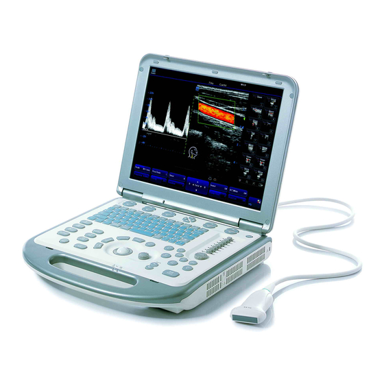
System Introduction Introduction of Each Unit... - Page 33 System Introduction Name Function Monitor Displays the images and parameters during scanning Control panel Operator-system interface or control Handle Used for carrying the system Connects a transducer to the main unit; or connects a Transducer port probe extend module Transducer locking Locks or unlocks the transducer connected with the main lever unit...
-
Page 34: Extend Modules
System Introduction 4.2 Extend Modules There are four extend modules available for the system: Probe extend module IO extend module V/A extend module ECG module 4.2.1 Probe Extend Module <1> <2> Name Function <1> Connector Connects to the transducer port of the main unit <2>... -
Page 35: Io Extend Module
System Introduction 4.2.2 IO Extend Module Name & Symbol Function 1 & 2 Connects USB devices. USB port Connects a display or projector VGA output port Connects serial port devices Serial port 5 & 6 Used for audio signals of D mode sound from Audio output port DVD output or audio comments Reserved... -
Page 36: V/A Extend Module
System Introduction 4.2.3 V/A Extend Module The module is connected to the USB port of the main unit via a USB cable. < > < > < > < > Name Function Audio input port Used for audio signal input Audio input port Used for audio signal input Composite video input port... -
Page 37: Control Panel
System Introduction Control Panel English Name Function Name Description soft menu Press to select the soft menu items displayed controls 1 on the bottom of the screen. Refer to the subsequent contents for specific functions. soft menu Press to select the soft menu items displayed controls 2 on the bottom of the screen. - Page 38 System Introduction English Name Function Name Description soft menu Press to select the soft menu items displayed controls 5 on the bottom of the screen. Refer to the subsequent contents for specific functions. soft menu Press to select the soft menu items displayed controls 6 on the bottom of the screen.
- Page 39 System Introduction English Name Function Name Description Clear Clear Press to clear the comments or measurement calipers on the screen. Info Patient Press to enter the [Patient Info] screen. information Exam Exam type Press to switch between exam types. Review Review Press to review the image files stored.
-
Page 40: Symbols
System Introduction English Name Function Name Description Press to enter the M mode. Print Print Press to print; user-defined key. Save Save Press to save; user-defined key. Depth Depth Press to increase or decrease the imaging depth. Freeze Freeze Press to freeze or unfreeze onscreen image. Indicator 1 Indicates if the main unit is connected to the power supply. - Page 41 System Introduction Symbol Meaning Type-BF device Caution No user serviceable parts (applied to the power adapter) Indoor, dry location use only (applied to the power adapter) Power button Transducer port Network port Parallel port Serial port S-VIDEO signal interface; VIDEO signal interface VGA signal;...
- Page 42 System Introduction Symbol Meaning Manufacturer Authorized representative in the European Community This product is provided with a CE marking in accordance with the regulations stated in Council Directive 93 / 42 / EEC concerning Medical Devices. The number adjacent to the CE marking (0123) is the number of the EU-notified body certified for meeting the requirements of the Directive.
-
Page 43: Set-Up & Connections
Set-up & Connections System Set-up Please read and understand the safety precautions before placing the system. Turn off the power and disconnect the system from all peripherals. Carry the system by holding the handle. Place the system in a desired location. Leave at least 20cm at the back and both sides of the system. -
Page 44: Connecting / Disconnecting A Transducer
When connecting or disconnecting a transducer, place it in a proper position, to prevent the transducer from falling off or becoming damaged. Only use the transducers provided by Mindray. Aftermarket transducers may result in damage or cause a fire. 5.3.1... -
Page 45: Disconnecting A Transducer
Set-up & Connections 5.3.2 Disconnecting a Transducer To disconnect a transducer: Toggle the locking lever to the bottom position to unlock the connector of the transducer. Pull the transducer connector straight out, as shown in the figure below. Connecting the Probe Extend Module Connect the probe extend module to the main unit via the transducer port, thus the transducer port is extended to two usable ports and one docking port. -
Page 46: Connecting Io Extend Module
Set-up & Connections Connecting IO Extend Module Connect the IO extend module to the main unit via the IO extend port, thus the data port is extended to two or more. See the following figure. IO extend module Connecting the V/A Extend Module Connect the V/A extend port module to the main unit via a USB port. -
Page 47: Connecting The Footswitch
Set-up & Connections Connecting the Footswitch Connect the footswitch to the main unit via a USB port. See the following figure. You can set the functions of the footswitch in the [Key Config] page. Refer to the section 17.2 for footswitch setup. Connecting / Removing a USB Memory Device WARNING:... -
Page 48: Installing A Graph / Text Printer
Set-up & Connections 5.10 Installing a Graph / Text Printer As shown in the figure below, a graph / text printer has a power cord and data cable. The power cord shall be directly connected to a wall receptacle as required. Power cord Data cable USB connector... -
Page 49: Installing A Video Printer
Set-up & Connections 5.11 Installing a Video Printer The video printers supported by the system include analog video printers and digital video printers. The video printers, whether analog or digital, consist of B / W printers and color printers. To connect an analog video printer ( SONY UP-897MD for example), the procedure is as follows (the methods for B / W printers and color printers are the same): Unpack the printer. - Page 50 Set-up & Connections Data cable Remote cable Power cord To connect a digital video printer (MITSUBISHI P93DC for example): Unpack the printer. Place the printer in the proper position. Connect the power cord of the printer to a receptacle. Use a USB cable to connect between the USB port of the system and the USB port of the printer.
-
Page 51: Use Of M-Pack
Set-up & Connections USB cable Power cord Please refer to the accompanying manuals of the printers for more details. 5.12 Use of M-Pack 5.12.1 Introduction of M-Pack M-Pack is a portable pack, which is used when you carry it on your shoulders to hold the system and simultaneously operate the system. -
Page 52: Use Of M-Pack
Set-up & Connections <1> <2> <4> <3> <5> <6> <7> Name Function <1> Accessory Bag Holds transducer and ultrasound gel, etc. <2> Upper Cover Holds and fixes the display of the system <3> Platform Holds and fixes the control panel of the system. <4>... - Page 53 Set-up & Connections <2> <3> <1> <4> Name <1> Display <2> Clips of the display <3> Fixing belt <4> Platform To fasten the M-Pack on the shoulders of the operator: Buckle up one end of one sling to the snap ring at the back of the platform, and buckle up the other sling as well.
- Page 54 Set-up & Connections After removing the transducer port cover and connecting the transducer, you are ready for operating the system. 5-12...
-
Page 55: Power On / Off
– immediately stop scanning. If the system continues to function improperly – fully shut down the system and contact Mindray Customer Service Department or sales representative. If you use the system in a persistent improperly functioning state – you may harm the patient or damage the equipment. - Page 56 If you find anything not functioning properly, this may indicate that the system is defective. In this case, shut down the system immediately and contact Mindray Customer Service Department or sales representative. NOTE: When you start the system or switch between transducers, you will hear clicking...
-
Page 57: Powering Off The System
Power ON / OFF Powering OFF the System You need to follow the correct procedures to power off the system. In addition, after you upgrade the software or when the system is down, you need to power off and restart it. To power off your system normally: Gently press the power button once on the upper right corner of the control... -
Page 58: Basic Screen And Operation
Basic Screen and Operation Basic Screen The system monitor displays ultrasound images, parameters, menus and measurement results window. The following diagram maps out the different areas, such as patient information, image parameter & menu, image-in-image thumbnail, image area, thumbnail of images saved, body mark, help information &... - Page 59 Check [Gender], [Age] or [Operator] in the [Patient Info] box in the upper left corner of the screen. Manufacturer logo - The Mindray’s logo is displayed in the upper left corner of the screen. Hospital name - The name of your hospital is displayed on the screen, and can be entered through Setup →...
-
Page 60: Image Parameter And Menu Area
Basic Screen and Operation system. It can be imported via DICOM or input manually. 7.1.2 Image Parameter and Menu Area The image parameter and menu are both displayed in this area. When no menu is available, this area displays the image parameters of the current mode. When an image menu is displayed, the imaging parameters will be covered by the menu. -
Page 61: Thumbnail Area Of Images Saved
Basic Screen and Operation 7.1.5 Thumbnail Area of Images Saved This area displays the thumbnails of saved images for the current patient. 7.1.6 Body Mark Area In the body mark status, this area displays the available body marks. 7.1.7 Area of Help Information and Cursor Icon The help information area displays various help information or progress bar in the current status. -
Page 62: System Status Area
Basic Screen and Operation The soft menu items are operated respectively through the five groups of soft menu controls <1>, <2>, <3>, <5> and <6>. The soft menu items can also be adjusted by [Set] or [Back] on the control panel. Move the cursor onto a soft menu item and press [Set] or [Back] to change the parameter of the item. - Page 63 Basic Screen and Operation pages. Check box: click to check or uncheck the item. Radio box: click to select the item. Content Drop-down list box: click [ ▼ ] to show the list and select an item. Entry box: enter characters manually via the qwerty. When the operation of a screen is complete, press the [OK] or [OK] and [Cancel] [Cancel] button to save or cancel the operation, and close the...
-
Page 64: Exam Preparation
Exam Preparation Before examining a new patient, press the <End Exam> key to CAUTION: end the exam of the previous patient, update the patient ID and information, to avoid mixing data of the next new patient. To Start an Exam You can start a patient exam in the following situations: New patient information: to start a new patient exam, you have to enter the patient information first, for details, please refer to “8.2.1 New Patient Information”;... - Page 65 Exam Preparation To exit the "Patient Info" screen In the [Patient Info] screen, click [OK] or press the <Info> key again to save the entered patient information and exit the screen. Click [Cancel] or press <Esc> to exit the screen without saving any of the entered patient data.
- Page 66 Exam Preparation Enter the ID If you deselect "Auto Generated ID", you need to enter an ID. If an ID that is already existed in the system is entered, the system prompts "The ID existed, load data", you can choose to import the data. Name Enter patient name through the keyboard.
- Page 67 Exam Preparation Secondary to enter the past history of the patient.. indications: CPT4 Code: to enter the CPT4 code. CPT4 to enter the CPT4 description. description: Exam specified information: ABD (Abdomen) (1) input height and weight of the patient. (2) BSA (Body surface area): after the height and weight are inputted, the system will automatically calculate the body surface area based on the formula which is set in the setup.
-
Page 68: Retrieve Patient Information From Istation
Exam Preparation (2) BSA (Body surface area): after the height and weight are inputted, the system will automatically calculate the body surface area based on the formula which is set in the setup. (3) BP & HR (4) RA Press (Right Atrium Pressure) VAS –... -
Page 69: Retrieve Patient Information From Worklist
Exam Preparation To search the patient information: 1. Select the data source of patient database, i.e. find where the system stores the patient data by default. 2. Input the searching condition: Item: including Name, ID, BOD and Exam Date, the default one is name; then enter a keyword in accordance with the Item selected. - Page 70 Exam Preparation Worklist screen. Query and import patient information from the DICOM Worklist server. The screen is as follows: To search the patient information: 1. Select the Worklist Server for the data source. 2. Input the searching condition: Select exam date period, click [Query] to search the patient data in the period. Enter patient ID, patient name, accession #, the system affords the result in real-time.
-
Page 71: Pause Exam & Continue Exam
Exam Preparation Pause Exam & Continue Exam 8.3.1 Pause Exam 1. Sometimes, you have to stop an uncompleted exam due to some special causes. When the exam is paused, the system can begin other exams. Procedures: a) Press the <Info> key to open the Patient Info screen. b) Click [Pause Exam]. -
Page 72: Activate Exam
Exam Preparation Activate Exam The exam that is ended within 24 hours can be activated. Specific operation: Enter iStation screen or Review screen. Select items to be activated in the list. Click [Activate Exam] and restore the exam. Tips: The system can automatically load the patient information and exam data to continue the exam. -
Page 73: Exam Types
Exam Types If the exam type is changed during a measurement, all CAUTION: measurement calipers on the image will be cleared. The data of general measurements will be lost, but the data of application measurements will be stored in the reports. Introduction of Exam Types The system can perform the following exam types: A-Abdomen - (Adult Abdomen) -
Page 74: Selecting Transducer And Exam Type
Exam Types Misc 3 (Miscellaneous 3) User-defined Selecting Transducer and Exam Type Opening Select Probe & Exam Screen Method one is: Directly connect a transducer or connect a transducer via the Probe Extend Module. Press [Info] key on the control panel to open the Patient Info screen. Enter the patient information. -
Page 75: Setting Exam Types
Exam Types You can also set user-defined shortcut key for saving exam mode image settings: <Setup>-[System Preset]-[Key Config]. [Exam Preset]: Click to enter the exam preset screen. [Close]: Click to cancel the exam and probe selection and exit the screen. Setting Exam Types In the Setup menu, select the [Exam Preset] item to enter the exam preset screen. -
Page 76: Exam Configuration
Exam Types To delete an exam supported by the current transducer, select the exam first, and then click to delete it. To add an exam for the current transducer, Select the exam from the Exam Library on the left and click to add it to the Exam Selected. -
Page 77: User-Defined Exam Types 9
Exam Types After an exam type is selected, Click [Rename] to change the name of the user-defined exam type, Click [Up] or [Down] to move the position of the exam mode. Click [Copy] to copy the parameters of the selected exam type. Select a second exam and, click [Paste] to paste the copied parameters to the secondly-selected exam type. -
Page 78: User-Defined Exam Types
Exam Types 9.3.3 User-defined Exam Types To define exam types for a transducer: Press [Setup] key on the control panel to show the [Setup] menu. Click [Exam Preset] item to open the [Exam Preset] screen. Click [Exam Config] tab to open [Exam Config] page. Click to select [User-defined 1] in the [Exam Mode] area. - Page 79 Exam Types Click [Body Mark Preset] to set body marks. Click [Image Preset] to set images. Click [OK] button to confirm.
-
Page 80: Image Modes
Image Modes The images displayed in this system are only reference for WARNING: diagnosis. M indray is not responsible for the correctness of diagnostic results. It is the responsibility of the clinician, who performs the exam, to capture the correct diagnostic results. -
Page 81: Switching Between Image Modes
Image Modes 10.2 Switching Between Image Modes Select and Switch B Mode control: press to enter the B Mode M Mode control: press to enter the M Mode Pulsed Wave Doppler control: press to enter the PW Doppler mode Continuous Wave Doppler control: press to enter the CW Doppler mode Color Mode control: press to enter Color Mode Power Mode control: press to enter Power Mode Dual-split display key: press to enter the Dual-split display mode. -
Page 82: Image Adjustments
Image Modes 10.3 Image Adjustments Imaging adjustments are performed through the following methods: 1. Adjustments through image menus or soft menus The image menus are located on the upper left corner of the screen. To adjust: a) Press [Set] or [Back] key; or b) Rotate the [Multifunction] knob. - Page 83 Image Modes In B Mode, you can change the display depth, flip (horizontally or vertically) images, rotate images, change the view field or magnify images. Depth To change depth, press keys in the lower right corner of the control panel. Press key to decrease the depth;...
- Page 84 Image Modes Th e iTouch feature is u sed to optimize multiple B Mode imaging parameters. The [iTouch] key is located below the gain sliders on the right side of the control panel. Press [iTouch] key to obtain the one-key optimization. To set the one-key optimization: Press [Setup] key on the control panel to show the [Setup] menu.
- Page 85 Image Modes Click [Line Density] item in the menu. Select between Low and High. Note: Changing Line Density will change B Mode frame rate (higher line density / lower frame rate, lower line density / higher frame rate). IP (Image Processing) Image Processing is a combination of image parameters, and the system has 8 IP preset combinations.
- Page 86 Image Modes Press the [Set] key a second time to fix the node in the new position. Repeat the above process to adjust multiple nodes. Pressing the [Back] key will cancel the active adjustment, returning the node back to the previous position.
-
Page 87: M Mode
Image Modes Adjust the γ item in the B image menu or soft menu, and the γ correction parameters are displayed on this menu. 10.3.2 M Mode 1. Changing M image Frequency To select the current transducer frequency: Click [Freq] item in the menu to select among frequency values. The transducer frequency is also displayed in the image parameter area in the upper left corner of the screen. -
Page 88: Color Mode
Image Modes Click [Focus Position] item in the menu. Change the position of focal zones. The focus position symbol is displayed on the right side of the image. Dynamic Range The Dynamic Range function is used to adjust contrast resolution of the B Mode image to compress or expand the gray display range. - Page 89 Image Modes B/C Wide Set and constrain the maximum width of the B Mode image to that of the Color RoI. Click [B/C Wide] item in the menu. Select [On] or [Off] to turn on / off the feature. Scale The Scale feature is used to adjust speed scale and change PRF.
- Page 90 Image Modes To invert the color bar manually: Click [Invert] item in the menu. Select [On] or [Off] to invert the color bar. You also can rotate the [Multifunction] knob to invert the color bar. Priority The Priority feature is used to show the flow priority displayed. Click [Priority] item in the menu.
-
Page 91: Power / Dirpower Mode
Image Modes Select among 0% through 100% in increments of 10%. When the position is changed, the transmit focusing delay changes accordingly. 10.3.4 Power / DirPower Mode Fundamental Power Mode is a non-directionally display of blood flow in the form of intensity as opposed to flow velocity. - Page 92 Image Modes Press and hold [iTouch] key to exit the one-key optimization. Gain Rotate the [iTouch] knob on the control panel to increase or decrease the gain. Scale To change PRF: Click [Scale] item in the menu. Select [Scale] among values. PW Steer This feature is used to steer the SV angle of PW flow with immobility of the linear transducer.
- Page 93 Image Modes Duplex allows two modes to be active at the same time. Triplex allows three modes to be active at the same time. Select [Duplex] as [On] to turn on B + PW. Select [Triplex] as [On] to turn on B + PW + Color or B + PW + Power. Colorize and Colorize Map Click [Colorize] in the menu to turn on / off the feature.
- Page 94 Image Modes Click [Auto Spectrum Calculation] to check the parameters for auto calculation in the screen; Click [Caliper] key to perform measurements; The results of auto spectrum calculation are displayed in the result window. Note: The result of auto calculation always displays at the top line of the result window, and will not disappear after new measurement calipers are added.
-
Page 95: Image Magnification
Image Modes Time Mark It is used to turn on / off Time Mark within the Doppler Spectral display. Click [Time Mark] in the menu. Select [On] or Off] to turn it on or off. HPRF (High Pulse Repetition Frequency) HPRF mode is used when detected velocities exceed the processing capabilities of the currently selected PW Doppler scale or when the selected anatomical site is too deep for the selected PW Doppler scale. -
Page 96: Image Parameter Preset
Image Modes It is the currently zooming region that is used for video output, image saving and print functions. Press <Exam>, <Info>, <iStation>, <Review> or enter Report or Preset, the system will exit zoom status. 10.4 Image Parameter Preset To enter the [Image Preset] screen: Press the Image Preset item in the Setup menu;... - Page 97 Image Modes B IP and THI IP Click the [BIP] or [THI IP] button, and the corresponding IP combination of settings can be entered, as shown in the figure below. You can set the parameter values of each IP combination, and click [OK] to store the new setup. B Gray Map and THI Gray Map Click [B Gray Map] or [THI Gray Map] on the left field to enter the settings of gray map, as shown in the figure below.
- Page 98 Image Modes Refer to the relevant B Mode chapter for adjustment of post processing curves. The system can store 8 different post processing maps, which are selectable through the image menu. 10-19...
-
Page 99: Special Imaging Modes
Special Imaging Modes The system supports the optional imaging modes as follows: Smart3D imaging iScape panoramic imaging NOTE: The ultrasound images, specially obtained in the Smart3D mode or iScape mode, are provided for reference only, not for confirming a diagnosis. Please use caution to avoid misdiagnosis. - Page 100 Special Imaging Modes c) Amniotic fluid(AF) isolation The region desired is isolated by amniotic fluid adequately The region to imaging is not covered by limbs or umbilical cord. d) The fetus keeps still. If there is a fetal movement, you need a rescan when the fetus is still.
-
Page 101: Smart3D Presetting
Special Imaging Modes 11.1.1.2 Basic Procedures for 3D Imaging Basic procedures for 3D imaging are as follows: 1. Select the proper exam mode. 2. Optimizing the 2D image. 3. Enter Smart 3D mode. 4. Set ROI (Region of Interest). 5. Capturing 3D images. 6. - Page 102 Special Imaging Modes 11-4...
-
Page 103: Enter/ Exit Smart3D
Special Imaging Modes Functions of the parameters are described in the following table. Parameter Description Display Format To set the image display format in 3D image view status: Single/Dual/Quad Tool To set the edit type in image edit mode: Inside Contour Outside Contour Inside Rect Outside Rect... -
Page 104: Image Capture
Special Imaging Modes Exiting Exiting from image acquisition preparation mode Click [Exit] in the menu; or press the <Esc> key or the user-defined key to exit Smart3D. Exiting from image acquisition mode Click [Exit] or press <ESC> to exit to image capture preparation status. Exiting from the view status Press user-defined key to exit Smart 3D;... -
Page 105: Procedures
Special Imaging Modes Type Parameter Description Function: to provide fast adjustment for entering 3D viewing direction in real-time or viewing status. Direction Selection: Up/Down, Down/Up, Left/Right, Right/Left, Front/Back, Back/Front. The commonly used direction is Up/Down. Function: to set the image display format in real-time displaying Display mode (only for 4D mode) or reviewing mode. -
Page 106: Image Browsing
Special Imaging Modes To setting the ROI, make sure: Set ROI on the 2D image with the largest section area of the fetal face. Set ROI a little larger than the fetal head. Take scanning the fetal face sagittally as an example, the largest ROI is set on the 2D image acquired from the sagittally section across the center of the face (with the largest face section area), as shown in the figure a below. - Page 107 Special Imaging Modes Press the [Freeze] key or the [Esc] key, or click the [Return] item in the menu. 11.1.6.1 Set the Review Window Click [Display Format] item to adjust the image display mode: single, dual or quad. Where, Select [Single], system displays one image, which can be a section image or a 3D image.
- Page 108 Special Imaging Modes Section A Section B Section C E.g. select A as the current window and roll the trackball, section lines (indicate the position of A) in the B and C window move, and image in A window changes. NOTE: In actual system displaying, different colors of the window box and the section line is used to identify the section A, B and C.
- Page 109 Special Imaging Modes Section A: corresponds to the 2D image in B mode. Section A is the sagittal section in fetal face up posture, as shown in the figure A above. Section B: it is the horizontal section in fetal face up posture, as shown in the figure B above.
- Page 110 Special Imaging Modes 11.1.6.4 Adjusting Parameters In 3D image browsing status, you can adjust the rendering, colorize, smooth and other parameters via 3D view menu and soft menu to optimize the image. See “11.1.2 Smart3D Presetting” for detailed parameter descriptions. 11-12...
- Page 111 Special Imaging Modes Parameter Description Function: to set the brightness of 3D image. Brightness Range: 0%-100%. 0% presents the minimum brightness, while 100% the maximum. Contrast Function: to set the contrast of 3D image. Colorize Function: to turn on/off the colorize map display. Function: to display colorize map of the image to optimize 3D image display.
- Page 112 Special Imaging Modes Parameter Description Function: to set the smoothness of 3D image. Smooth Tip: insufficient smoothness can result in a fuzzy image; however, over smoothness will lead to image distortion. Auto Rotation Function: to turn on the 3D image auto rotation function. Function: to select 3D viewing direction for entering 3D viewing status.
- Page 113 Special Imaging Modes Auto Rotation In 3D image viewing status, click [Auto Rot.], the system displays the 3D image only and enters the auto rotation preparation status. Click [Direction] to set the auto rotation direction. Click [Repeat Mode] to set the auto rotation mode. Click [Speed] to set the auto rotation speed.
- Page 114 Special Imaging Modes If the Eraser mode is selected, with the eraser moving the region that will be cut is defined in real time. Click [Undo] in the soft menu to undo the last cutting; click [Restore] to restore the cut region;...
-
Page 115: Reset Roi
Special Imaging Modes Operation: The operation is the same as adding comment and body mark in B image mode. 11.1.7 Reset ROI Reset ROI is to reset the region of interest to rebuild the 3D image. It’s performed on Freeze images. NOTE: 1. -
Page 116: Enter Or Exit Iscape
Special Imaging Modes You can perform the iScape panoramic imaging feature on B real time images using all linear and convex transducers. iScape panoramic imaging constructs an extended image from CAUTION: individual image frames. The quality of the resulting image is user-dependent and requires operator skill and additional practice to become fully proficient. -
Page 117: Review The Extended Image
Special Imaging Modes Select [Return to Capture] in the menu. To exit iScape in the iScape capture mode: Press the [Esc] key; or Press the [B] key; or Press the user-defined iScape panoramic imaging key. 11.2.3 Review the Extended Image After completing the image capture, you can piece images together and then enter the iScape review mode. -
Page 118: Review The Captured Images Frame By Frame
Special Imaging Modes 11.2.4 Review the Captured Images Frame by Frame In the iScape review mode, you can review the captured images frame by frame, or perform measurements on these images. To review the images: Click [Review Cine] in the menu and enter the cine review mode. The cine review will start in manual fashion. -
Page 119: Settings For Free Xros M
Special Imaging Modes 11.3.1 Settings for Free Xros M 11.3.1.1 Shortcut Key Preset Define the shortcut key for entering Free Xros M mode through the path: <Setup> - [System Preset] - [Key Config], refer to “17.2 System Preset” for details. 11.3.1.2 Parameter Preset Set Free Xros M image parameters through the path: <Setup>- [Image Preset] - [Free Xros M]. -
Page 120: Free Xros M Image Parameters
Special Imaging Modes 11.3.4 Free Xros M Image Parameters In Free Xros M mode imaging, the image parameter area in the upper left corner of the screen displays the real-time parameter values as follows: Display G 62 Parameter Free Xros M Gain Free Xros M Speed Parameters that can be adjusted to optimize the Free Xros M mode image are indicated in the following. - Page 121 Special Imaging Modes Operation Position Adjustment When the M-mark line is activated, move the trackball left and right to adjust the position. The direction is recognized by the arrow at the end of the line. Angle Adjustment When the M-mark line is activated, move the trackball to adjust the fulcrum of the line, and adjust the angle via the [Angle] in the soft menu or the multifunctional knob.
-
Page 122: Cine Review
Cine Review After you press the [Freeze] key, the system allows you to review and edit the images prior to the image frozen. This function is called as cine review. The magnified images can also be reviewed after the [Freeze] key is pressed, and the operating method is the same. You can change post processing maps, perform measurements, add comments and body marks on the images being reviewed. -
Page 123: Auto Cine Review
Cine Review The cine progress bar at the bottom of the screen (as shown in the figure below): the whole bar represents the total frame number. The two numerals in the lower right corner respectively indicate the current frame number and the total frame number. The slider indicates the frame position currently reviewed. -
Page 124: Setting Region Of Auto Review
Cine Review 12.5 Setting Region of Auto Review You can set a segment of cine loop which can be reviewed automatically. After the auto review region is set, the auto cine review can only be performed within this region; but the manual cine review can be performed beyond this region. -
Page 125: Cine Setup
Cine Review 12.7 Cine Setup 12.7.1 Setting Cine Length You can set the cine length in the system setup screen. Enter the system setup screen, and open the [General] page. In the Storage field, the Cine Length item is located in the middle, as shown in the figure below. -
Page 126: Measurements
Measurements Be sure to measure areas of interest from the most WARNING: optimal image plane to avoid misdiagnosis from inaccurate measurement values. To obtain accurate Doppler flow measurement values, make sure the transmitting beam is not perpendicular to the flow, otherwise false readings and potential misdiagnosis may result. -
Page 127: General Measurements
Measurements 13.2 General Measurements 13.2.1 General Measurements – 2D The 2D general measurement consists of B, Color and Power/DirPower general measurements. The measurements listed below can be performed in 2D: Measurement tool Function Distance The distance between two points of interest. Depth The distance between transducer surface and the probing point along ultrasound beam. -
Page 128: General Measurements - Doppler
Measurements 13.2.3 General Measurements - Doppler General measurements in the D mode are also called “Doppler measurements.” The measurement tools are as follows. Measurement tool Function Time The time interval between any two points. Heart rate N intervals (n≤8) are measured to calculate a PW Mode derived HR value in Beats Per Minute (BPM). -
Page 129: Comments (Annotations)
Comments (Annotations) You must ensure that the entered comments are correct. WARNING: Incorrect comments may cause misdiagnosis! Comments can be added to an ultrasound image to bring to attention, notate or communicate information observed during the examination. You can add comments to: zoomed image cine review image real-time image... -
Page 130: Soft Menu For Comments
Comments (Annotations) (Gynecology), OB (Obstetrics), Urology, SMP (Small Part), Vascular, Pediatrics, Nerve and Emergency. To customize the comment text library, press <Setup> key to select [Comment Preset] and open the comment preset screen. After you customize the comment text library for an exam, you will see the customized comment texts when you open the comment text library menu in this exam mode. -
Page 131: Adding Comments
Comments (Annotations) ABC Display Click [ABC Display] to display or hide the added comments. Assign the user-defined key for the function in “[Setup] → [System Preset] → [Key Config]”. Delete a word or all comments Click [Erase All Text] to delete all texts. Click [Delete Word] to delete the word in the reserved order. -
Page 132: Adding An Arrow
Comments (Annotations) Once you find the desired comment text, press [Set] or [Enter] to confirm the comment text and exit the comment status. The added comment text turns to yellow color. 14.3.3 Adding an Arrow You can add an arrow to a location where you want to pay attention. Press the [Arrow] key, and an arrow will appear in the default position. -
Page 133: Modifying (Editing) Arrows
Comments (Annotations) Press the [Backspace] key to delete the comment character or text on the left side of the cursor. Roll the trackball or press the [Set] key to confirm the modification and to exit the edit status, and the color of the comments turns to yellow. 14.5.2 Modifying (Editing) Arrows Move the cursor on the arrow that needs to be modified. -
Page 134: Deleting All Comments (Characters, Texts Or Arrows)
Comments (Annotations) 14.6.4 Deleting all Comments (Characters, Texts or Arrows) Click [Erase All Text] to delete all the comment items on the screen. You can also assign the corresponding shortcut key for the function in “[Setup] → [System Preset] → [Key Config]”. -
Page 135: User-Defined Comments
Comments (Annotations) 14.7.2 User-defined Comments You can customize user-defined comments for an exam mode according to your preferences. The customized comments will display in the corresponding exam mode. The operational steps are as follows: To open the [Comment Preset] screen, select Comment Preset in the Setup menu. The following example is comment preset in A-Abdomen mode. - Page 136 Comments (Annotations) Withdraw or Delete a user-defined comment: Withdraw an item (from the library or user-defined) in the Selected Items box: Select an item in Selected Items box, and click to withdraw it to the Available Items box. To withdraw all items, click Note: After an item is withdrawn to the Available Items box, it will not appear in the comment menu.
-
Page 137: Body Marks (Pictograms)
Body Marks (Pictograms) The Body Mark (Pictogram) feature is used for indicating the exam position of the patient and transducer position and orientation. 15.1 Entering / Exiting Body Mark Mode To enter the Body Mark status: Press to enter the body mark selection status. To exit the Body Mark status: Press [Body Mark] again to exit the body mark status;... -
Page 138: Moving Body Marks
Body Marks (Pictograms) Enter the Body Mark status; use the soft menu control to click [Library] to select the body mark category. The exam-dependent body marks will appear above the soft menu. Move the cursor onto the desired body mark to highlight your choice (See the figure below). -
Page 139: Deleting Body Marks
Body Marks (Pictograms) 15.6 Deleting Body Marks To delete a Body Mark: Use the trackball to position the selection pointer over the Body Mark graphic. Click the [Set] key to select the Body Mark graphic. Press the [Clear] key to delete the selected body mark. NOTE: In the Body Mark mode, if no object is selected, pressing the [Clear] key will clear all comments, body marks and general measurements from the screen. - Page 140 Body Marks (Pictograms) 2 Select the exam type that you will preset the Body Mark presets from Exam Mode drop down menu. 3 Set library name: enter the name for the setting body mark library. 4 Select the target library where the body mark is applied through the Available Items drop-down list.
- Page 141 Body Marks (Pictograms) Note: You can edit, delete, or export a user-defined graphic. In addition, you can create a Body Mark graphic with a draw tool or add it from loading. The method of loading and exporting is similar to that in the comment preset. The file format is *.BIN. The following is only to introduce the manual edit of body marks.
- Page 142 Body Marks (Pictograms) Select a body mark on the current screen and click [Copy] to enter the body mark drawing screen, thus you can edit the copied body mark. In addition, you can click [Add] to enter body mark drawing screen: The drawing tools are described as follows;...
- Page 143 Body Marks (Pictograms) Brush Eraser Up/down flip Left/right flip Zoom in Zoom out Rotate Drag You can select on the screen, to adjust position of the transducer indicator on the body mark and rotate the [Multifunction] knob to change direction of the indicator. After the drawing of a body mark is complete, click [OK] to save it and exit the user-defined body mark status.
-
Page 144: Patient Data Management
2. The system patient database space is limited, please back up or clear patient data in time. 3. Mindray is not responsible for lost data if you DO NOT follow suggested backup procedures. 16.1 Patient Information Management 16.1.1 Enter Patient Information The general patient information and exam information are entered through the Patient Info screen, for details;... -
Page 145: Image File Management
Patient Data Management 16.2 Image File Management You can store the image files either in the patient database in the system, or to external memory devices. For a saved image, you can perform operations like image reviewing, analyzing and demonstration (iVision). 16.2.1 Memory Media System supported memory media including: System hard disk... -
Page 146: Image Storage Preset
Patient Data Management Single-frame file format, used to save the current screen in the compressed format; you can set the compression ratio. TIFF: Single-frame export format Multi-medium files (AVI) Multi-frame file format, general cine file format. DICOM files (DCM) DICOM standard files format, single-frame or multi-frame format, used to record patient information and images;... -
Page 147: Quickly Saving Images To Usb Flash Drive
Patient Data Management select “Send Single Frame Image to Local Disk” in the Output page of Function field on the right side. 2. Press the user-defined key to save the image. In the image screen, press the user-defined key to save the current single-frame image, and the image is saved with the default file name in the default file directory in the FRM format. -
Page 148: Quickly Saving Full Screen Image To The System
Patient Data Management 16.2.6 Quickly Saving Full Screen Image to the System This function can save the current full screen image to the system with image in scanning mode. 1. Set the user-defined key through the path: [Setup](by pressing <Setup>)→ [System Preset]→... - Page 149 Patient Data Management To exit Review: Click [Exit] on the Review screen; or, Press <ESC> or <Review> again. Basic operations Select an exam item in the Exam History area. The selected item is highlighted. Click [Info] or [Report] to view patient information or report. Double-click a thumbnail to view and analyze an image.
-
Page 150: Ivision
Patient Data Management [Send To]: click to send the selected image to other location, DICOM server, printer and etc. [Delete]: click to delete the selected image. Layout: You can select the layout of the Review screen among three selections: 1×1, 2×2 and 4×4. - Page 151 Patient Data Management 3. Select an item in the list, and click [Start] to begin the demonstration. 4. Click [Exit] or press <ESC> to exit the iVision status. The iVision screen is shown as follows: Demonstration item The demonstration items are the image files in the formats that the system supports. You can add the exam data in patient database or system supported image files and folders to demonstration list.
-
Page 152: Sending Image File
Patient Data Management [Delete]: to delete the selected file or catalog in the file list. [Clear]: to clear all the files or catalogs in the file list. Demonstration mode Interval: refer to the interval time for demonstration, the adjusting range is 1~500s. Option of Demo You can choose whether to repeat the demonstration or exit after a demonstration is completed. -
Page 153: Report Management
Patient Data Management b) DCM format transfer: DCM (including single-frame DCM and multi-frame DCM). c) You can also select to export report in RTF/PDF format. For DICOM Storage or Print server, select the DICOM Storage or Print server. For a video printer, send images to the video printer connected with the system. For a graph/ text printer, send the images to the default graph/ text printer. -
Page 154: Patient Data Management (Istation)
Patient Data Management 3. Check [Export Report]. Select report format in the drop-down list (RTF or PDF). Click [OK] to export the report to destination. Printing report Use a connected graph/text printer to print a report. 16.4 Patient Data Management (iStation) The patient data include basic patient information, exam information, image files and reports. -
Page 155: Viewing Patient Information
Patient Data Management 16.4.1 Viewing Patient Information Data Source Select the data source of patient data, the system patient database is default. Patient list Display patient information, exam mode, number of images and cines, exam state, backed up or not. Info Select an exam of a patient, click [Info] on the right side to display the patient information of this exam. -
Page 156: Patient Data Management
Patient Data Management 2. Set search conditions of Name, ID, DOB, and Exam Date in the "Item" drop-down list. 3. Enter the keyword in accordance with the “Item” selected, and the system searches and displays the results in the patient list. 4. -
Page 157: Examinations
Patient Data Management 2. Select operations: Click [Restore Items] to restore the item back to iStation. Click [Delete] to delete the item permanently, and the item can never be restored again. Click [Restore All Items] to restore all the items back to iStation. Click [Empty Recycle Bin] to empty the recycle bin and all items can never be restored again. -
Page 158: Network Storage Setting
Patient Data Management 16.5.1 Network Storage Setting Open “[Setup]→[Network Preset]→[Network Storage]” to perform network storage setting. (For details, please refer to Setup chapter.) Name Description Service Name Name of the device, cannot be empty Destination Name of the device, cannot be empty Device IP Address IP address of the network service device, cannot be empty... -
Page 159: Network Storage
Patient Data Management Cancel Click to cancel parameter setting Update To save the changed parameters. To set default To set as the default server for network storage server Delete Click to delete the selected service in the service list Exit Click to exit the screen. -
Page 160: Backing Up And Erasing Files Through Dvd Drive
Patient Data Management Information of all print tasks is displayed in the list, including ID, name, status (being printing or suspended), and submit time. You can check the manager to see if there is any failure task. To delete a print task Select the print task in the list and click [Delete]. -
Page 161: Task Manager
Patient Data Management 4. After the writing process is completed, click to pop up the Disc Option dialogue box, and select [Eject] to eject the CD/DVD. To erase data from a CD/DVD 1. Double-click the symbol to pop up the Disc Option screen, as shown in the figure below. - Page 162 Patient Data Management The system supports three types of task management: Storage Task: displays the DICOM storage task. Print Task: displays the DICOM print task. Media Storage Task: DICOM media storage task (including disc and USB devices). Backup task (system-relevant format): select the exam to be backed up in iStation and click [Backup].
-
Page 163: Reviewing The Avi Files
Patient Data Management When the task management icon displays as , it means no task is undergoing or failure. 16.9 Reviewing the AVI Files To review the AVI files, which are stored in the ultrasound system, in the environment of PowerPoint in a PC, you will perform the following operations to ensure the quality of images: On the PowerPoint screen, select [Media Player], and then select: View →... -
Page 164: Add/ Delete A User
Patient Data Management Log on the system: 1. If the system requires you to log on the system before you access the data, you can see the following dialogue box. 2. Select the user name in the drop-down list of User Name. 3. - Page 165 Patient Data Management 2. Click [Add] to enter the following page. 3. Enter the user name (you are not allowed to enter the same name or modify the name already exist). 4. Enter the password and the confirmed password (the password is consist of 6-16 characters) 5.
-
Page 166: Modify Password
Patient Data Management 2. Select the user to be deleted in the User List (current operator, admin and Emergency user can’t be deleted), click [Delete] to delete the selected user. 16.10.5 Modify Password The system administrator can modify password of all users. The administrator password by factory is empty;... - Page 167 Patient Data Management 3. Enter the previous and the new password in the dialogue box. 4. Click [OK] to exit. 16-24...
-
Page 168: Parameter Setup
CAUTION: When the setup data is changed, be sure to save the preferences according to the methods described in this chapter. Mindray is not responsible for the loss of the setup data. 17.1 Entering / Exiting Setup To enter the setup status: Press the [Setup] key on the control panel;... -
Page 169: System Setup
Parameter Setup 17.2 System Setup The system setup contains several pages, i.e., Region, General, Image Preset, Meas, OB, Key Config, Biopsy, Option and Admin. To confirm the modified parameters, click [OK]. To cancel the modified parameters, click [Cancel]. Click the [Load Factory] button to restore the current page to the factory settings. The content of each page is described as follows. - Page 170 Parameter Setup Type Function Description Save Single Frame Image to To send single-frame image to HDD Local Disk Save Cine to Local To save cine file to HDD in cin format. Save Full Screen Image to To save single-frame image to HDD. Local Send Image to USB disk (S1) To send image to USB storage...
-
Page 171: Exam Mode Preset
Parameter Setup User-defined key setting procedure (Take <Print> or <Save> key as an example): Select [Key Config] tab to open the [Key Config] page. See the figure below. Click to select [Print] or [Save]. Click to select a function in the [Output] page. Click [OK]. -
Page 172: Image Parameter Preset
Parameter Setup 17.4 Image Parameter Preset Refer to “10.4 Image Parameter Preset”. 17.5 Comment Preset Refer to “14.7 Comment Preset”. 17.6 Body Mark Preset Refer to “15.8 Body Mark Preset”. 17.7 Measurement Preset Refer to Measurement Preset in the Operator’s Manual [Advanced Volume]. 17.8 Soft-key and Menu Preset You can preset parameter items in image modes for all types of transducers, in the menu (displayed at the bottom of the screen) and the menu (displayed on the upper left side of... - Page 173 Parameter Setup Available Items on the left side: You can select these items and move them to the Softkey page the right side. Items in the Softkey page on the right side: These items will display in the menu. Delete items from the soft menu To delete one item: Move the cursor onto an item in Softkey page on the right side, which is highlighted, click [Set], and then move the cursor onto and click [Set].
- Page 174 Parameter Setup Click [Down] The item will move down, and the item below it will move up. 2. Parameter Items Displayed in Image Menu To preset parameter items in image menu, enter [Image Params] page in the [Key and Menu Preset] screen, select Probe Type as Linear and select Image Mode as B. Open the Menu page on the right side.
-
Page 175: Peripheral Setup
Parameter Setup 17.9 Peripheral Setup Click [Setup] key to show the Setup menu, and select [Peripheral] in the Setup menu to open the [Peripheral Config] screen. The [Peripheral Config] screen is used to set up printer, recorder and I/O configuration. Set Up Printer .The settings of a printer include: set a printer, add a printer, change printer attribute, set paper size and direction. - Page 176 Parameter Setup To set paper direction, select between Landscape and Portrait. Set Up Recorder In the [Peripheral Config] screen, click Recorder to open the Recorder page. The system supports DVR and VCR. See the figure below. DVR Settings Settings Available Selections Svideo Input Channel CVBS...
-
Page 177: Network Preset
Parameter Setup I/O Config In the [Peripheral Config] screen, click I/O Config to open the I/O Config page. You can set up video input port, video output size and mode, as well as color temperature, brightness and contrast for display. 17.10 Network Preset Please refer to the DICOM chapter and “Network Storage”... -
Page 178: Importing Setup Data
17.12 Maintenance The [Maintenance] item is designed for you to update the system software or other special functions. If you require these functions, please contact Mindray Customer Service Department or sales representative. Through the menu, you can perform net update, remote desktop, system test, log operation, etc. -
Page 179: Probes And Biopsy
Probes and Biopsy Note: For details of storage time and condition for disinfected probes or sterilized probes and brackets, please refer to Technical standard for Disinfection of Medical and Health Structures 18.1 Probes The system supports the following probes: Probe Model Illustration 3C5s 6C2s... - Page 180 Probes and Biopsy Probe Model Illustration 10L4s L14-6s 6LB7s 6CV1s 6LE7s 2P2s 3C1s 18-2...
-
Page 181: Name And Function Of Each Part Of The Probe
Probes and Biopsy Probe Model Illustration 7L5s 7LT4s L11-4s P4-2s C5-2s 18.1.1 Name and Function of Each Part of the Probe The basic structures and corresponding functions of probes are basically the same; the following will take probe 7L4s as an example to illustrate. 18-3... - Page 182 Probes and Biopsy <1> <3> <2> <4> Name Function It converts the electrical signal into ultrasound signal, making the sound beams focus in the given direction; meanwhile, it will receive the ultrasound signal and then <1> Probe head convert the received signal into electrical signal. The lens on the surface is the acoustic lens.
- Page 183 Probes and Biopsy 6LE7s probe: Name Function <1> Transducer head It utilizes the piezoelectric effect to convert electrical signals into ultrasound waves, which are transmitted to the body, and to generate electrical signals when receiving the reflected ultrasound waves (echoes).The lens on the surface is the acoustic lens.
- Page 184 Probes and Biopsy 6LB7s probe: Name Function It utilizes the piezoelectric effect to convert <1> <1>Transducer head electrical signals into ultrasound waves, which (convex) are transmitted to the body, and to generate <2> electrical signals when receiving the reflected <2>Transducer head (linear) ultrasound waves (echoes).The lens on the surface is the acoustic lens.
-
Page 185: Procedures For Operating
Probes and Biopsy 18.1.2 Orientation of the Ultrasound Image and the Probe Head The orientation of the ultrasound image and the probe are shown as below. The “Mark” side of the ultrasound image on the monitor corresponds to the mark side of the probe. Check the orientation before the examination (Here takes linear probe as an example). - Page 186 Probes and Biopsy Procedures for operating (with biopsy function): Inspection before examination Connection to the ultrasonic diagnostic system Examinations Biopsy procedure Disconnection to the ultrasonic diagnostic system Sterilization of the needle- guided bracket Wiping off the ultrasound gel Inspection after use Washing the transducer with water Storage Draining/drying...
- Page 187 Probes and Biopsy Procedures for operating (with no biopsy function): Inspection before examination Connection to the ultrasonic diagnostic system Examinations Disconnection to the ultrasonic diagnostic system Wiping off the ultrasound gel Washing the transducer with water Draining/drying Disinfection Immersion into disinfectant Removing the transducer from disinfectant Rinsing the transducer into sterile water...
-
Page 188: Wearing The Probe Sheath
Probes and Biopsy Disinfect the probe and sterilize the needle-guided bracket WARNING: before and after an ultrasound-guided biopsy procedure is performed. Failure to do so may cause the probe and the needle-guided bracket become source of infection. 18.1.4 Wearing the Probe Sheath A legally marketed probe sheath must be installed over the probe before performing intra-cavitary and intra-operative examination. -
Page 189: When The Immersion Method Is Used (For 6Lb7S And 6Le7S)
Probes and Biopsy 3. Secure the sheath with enclosed elastic 4. Inspect the sheath to ensure there is bands. no hole or tear. 18.1.5 When the Immersion Method is used (for 6LB7s and 6LE7s) The transducer manufacturer recommends a syringe: CIVCO 610-224. Here takes transducer 6LB7 as an example to introduce the immersion method. - Page 190 Probes and Biopsy 1. Put on the transducer cover. For the procedures of putting on the transducer sheath, refer to subsection above. Check the transducer sheath for wrinkles and gaps. 2. Fill syringe with sterile water and connect extension tube to syringe, discharge all air in the tube.
- Page 191 Probes and Biopsy 4. Orientate the transducer upward to discharge air in the transducer cover. 18-13...
- Page 192 Probes and Biopsy 5. Turn the valve of the syringe to the position shown in the right figure, and then push the plunger of the syringe to discharge the air. 6. Return the valve of the syringe to the original position; orientate the transducer downward to discharge sterile water.
-
Page 193: Probes Cleaning And Disinfection (Or Sterilization)
Probes and Biopsy 18.1.6 Probes Cleaning and Disinfection (or Sterilization) After completing each examination, clean and disinfect (or sterilize) the probes as required. When biopsy procedures have been performed, be sure to sterilize the needle-guided bracket. Fail to do so may result in the probe and the needle-guided bracket to becoming sources of infection. - Page 194 Disinfecting by Immersion 1. Wear sterile gloves to prevent infection. 2. Clean the transducer before disinfecting it.MINDRAY recommends the following solutions to disinfect the transducer. Refer to the instructions provided by the chemical manufacturer concerning concentration of the disinfectant solution, method of disinfection and dilution and cautions during use.Do not soak the transducer connector or the cable near it into...
- Page 195 Probes and Biopsy Strain relief Probe handle NOTE: 1. Observe the graph here carefully to immerse the transducer. Only soak parts of the transducer below the strain relief. Repeated disinfection will eventually damage the probe, please check the probe performance periodically. Compatible Disinfectants Manufacturer Trade Name...
-
Page 196: Probes 18
For intra-operative probes (7LT4s), they have to be sterilized after completing each examination. 1. Wear sterile gloves to prevent infection. 2. Clean the probe before sterilizing it. MINDRAY recommends the following solutions to sterilize the probe. Hydrogen Peroxide and Peroxyacetic Acid -based sterilization solution... -
Page 197: Storage And Transportation
2. Store and transport the probe under the specified ambient conditions. 3. When the probe is sent to MINDRAY Customer Service Department or sales representative for repair, be sure to disinfect it and keep it in the carrying case to prevent infection. - Page 198 If an abnormality is found on the needle-guided bracket, immediately stop using it and contact MINDRAY Customer Service Department or sales representative. 4. DO NOT use a needle-guided bracket when scanning is performed.
-
Page 199: Needle-Guided Brackets
A needle-guided bracket is available for purchase as an optional accessory; it is used in combination with the probe. Some of the probes have matched needle-guided bracket and needles. To order needle-guided brackets, contact MINDRAY Customer Service Department or sales representative. - Page 200 Probes and Biopsy NGB-004 Locking nut Retaining clamp Needle guide Locating bulge Locating groove Probe 18-22...
- Page 201 Probes and Biopsy NGB-005 Clamping knob of the needle guide Needle guide rack Needle guide Clamp Locating pit Locating pit Needle guide hole Grip knob Locating groove Needle-guided bracket Probe NGB-006 Metal/needle detachable needle-guided bracket: 18-23...
- Page 202 Probes and Biopsy Name Description <1> Support of Used for installing the needle-guided bracket on the needle-guided probe. bracket <2> Groove and tab of Respectively matched with the tab and groove of the probe. the needle-guided bracket <3> Angle adjusting There are 3 types of angles available to be adjusted.
- Page 203 Probes and Biopsy Plastic/needle detachable needle-guided bracket: Name Description Support of Used for installing the needle-guided bracket on the <1> needle-guided probe. bracket Used for determining the angle of the biopsy; there are <2> Angle block three specifications of blocks of angle. Used for installing biopsy needle;...
- Page 204 Probes and Biopsy NGB-007 Metal/needle detachable needle-guided bracket: Name Description Support of Used for installing the needle-guided bracket on the <1> needle-guided probe. bracket Groove and tab of Respectively matched with the tab and groove of the <2> the needle-guided probe.
- Page 205 Probes and Biopsy Name Description Pinch nut of <10> needle-guided Used for locking the needle-guided bracket and the probe. bracket Plastic/needle detachable needle-guided bracket: Name Description Support of <1> needle-guided Used for installing the needle-guided bracket on the probe. bracket Used for determining the angle of the biopsy;...
- Page 206 Probes and Biopsy NGB-008 Plastic/needle-detachable needle-guided bracket: <6> <5> <3> <2> <7> <1> <4> Name Description Support of Used for installing the needle-guided bracket <1> on the transducer needle-guided bracket Used for determining the angle of the biopsy; <2> Angle block there are two specifications of blocks of angle Used for installing biopsy needle;...
- Page 207 Probes and Biopsy Name Description Clamp of Used for installing the needle-guided bracket on <1> needle-guided bracket the transducer Groove and tab of Respectively matched with the tab and groove of <2> needle-guided bracket the transducer There are 2 types of angles available to be <3>...
- Page 208 Probes and Biopsy <5> Needle distance scales Indicate distance between needle and the transducer head surface <6> Guiding block Used for installing biopsy needle; there are five specifications of guiding blocks for different needles <7> Knob of fixing the needle Used for fixing the needle <8>...
- Page 209 Probes and Biopsy Name Description Grooves of the needle-guided Matched with the tabs of the probe. bracket NGB-011 Needle guide Clamping knob of the needle Locating pit Clamp Needle guide hole Locating groove Grip Needle guide rack knob Needle-guided bracket Probe NGB-012 Metal/needle detachable needle-guided bracket:...
- Page 210 Probes and Biopsy Name Description Support Used for installing the needle-guided bracket on the <1> needle-guided transducer bracket Groove and tab of Respectively matched with the tab and groove of the <2> needle-guided transducer bracket Angle adjusting <3> There are 3 types of angles available to be adjusted base Angle shift sign(40°, <4>...
- Page 211 Probes and Biopsy Plastic/needle detachable needle-guided bracket: Name Description Used for installing biopsy needle; there are five <1> Guiding block specifications of guiding blocks for different biopsy needles Used for determining the angle of the biopsy; there are <2> Angle block three specifications of blocks of angle Support of...
- Page 212 Probes and Biopsy NGB-015 Guiding Groove V-shaped guiding block Lock pin Needle type Needle fixing nut adjusting base Needle type dial scale V-shaped cover Clamp Angle block Angle adjusting base Pinch nut Angle pinch nut Angle shift sign NGB-016 < >...
- Page 213 Be sure to perform inspections before and after use of the needle-guided bracket. If an abnormality is found on the needle-guided bracket, immediately stop using it and contact MINDRAY Customer Service Department or sales representative. 1. Sterilize the needle-guided bracket before and after use.
- Page 214 Probes and Biopsy (3) When the retaining clamp is turned to the right position, the locking nut will lock the retaining clamp and the needle-guided bracket is then mounted to the right position. NGB-005 (1) Inosculate the locating groove on the clamp with the two raised edges on the probe head and aligning the locating pit of the clamp to the convex point on the probe head.
- Page 215 Probes and Biopsy (2) Hold the probe by one hand, select proper needle-guided bracket, and hold it with the other hand. Align the narrow end tab of the needle-guided bracket with the groove of the probe, then push the needle-guided bracket forward, making the tabs and the grooves of the needle-guided bracket to match with the grooves and tabs of the probe.
- Page 216 Probes and Biopsy (3) Screw the pinch nut of the needle-guided bracket to confirm that the needle-guided bracket is properly installed on the probe. (4) Select a proper guiding block and push it into the groove above the angle block, and clamp it tightly.
- Page 217 Probes and Biopsy (5) Insert a biopsy needle with the same specification as that of the guiding block into the hole of the guiding block. NGB-008 Metal/needle-detachable needle-guided bracket; (1) Put on the transducer cover. (2) Select a proper needle-guided bracket, and match the groove and tab with the tab and groove of the transducer respectively.
- Page 218 Probes and Biopsy (2) Hold the transducer by one hand, select proper needle-guided bracket, and hold it with the other hand, and align the tab of the needle-guided bracket with the groove of the transducer, then push the needle-guided bracket along the arrow, making the tab of the needle-guided bracket to match with the groove of the transducer.
- Page 219 Probes and Biopsy (3) Select a proper guiding block and thread the knob of fixing the guiding block through the hole of installing guiding block, move the guiding block to the desired position, then turn tightly the knob of fixing the guiding block to fix the guiding block on the support of needle-guided bracket.
- Page 220 Probes and Biopsy (5) Insert a biopsy needle with the same specification as that of the guiding block into the hole of the guiding block. NGB-011 (1) Inosculate the locating groove on the clamp with the two raised edges on the probe head and align the locating pit of the clamp to the convex point on the probe head.
-
Page 221: Entering Or Exiting Biopsy Menu
Probes and Biopsy NGB-016 (1) Put on the probe sheath. (2) Select a proper needle-guided bracket, and match the groove with the tab of the probe. Mount the bracket onto the probe. (3) Screw the pinch nut of the needle-guided bracket to confirm that the needle-guided bracket is properly installed on the probe. -
Page 222: Displaying Biopsy Guide Lines
Probes and Biopsy below. To exit the biopsy, Press the [Esc] key. Or Move the cursor onto the Biopsy menu title and navigate to select other menus in the pop-up menu. WARNING: Do not freeze an image while performing biopsy procedure. 18.2.5 Displaying Biopsy Guide Lines Select biopsy bracket angle. -
Page 223: Removing The Needle-Guided Bracket
Probes and Biopsy [Verify] in the Biopsy menu to open the [Biopsy Verify] menu. Click Adjust position Changing the position value can move the biopsy guide line horizontally. 1) Press [Set] to increase the position value. 2) Press [Back] to decrease the position value. 3) Or rotate the [Multifunction] knob to increase or decrease the position value. - Page 224 Probes and Biopsy NGB-006 Metal needle-guided bracket: (1) Screw out the nut on the guiding block to loose the guiding block and the needle-guided bracket. (2) Take the guiding block away in the direction of the needle tail, and then separate the needle from the probe and the residual parts of the needle-guided bracket.
- Page 225 Probes and Biopsy Plastic needle-guided bracket: (1) Remove the guiding block slightly along the direction of the needle’s tail. (2) Separate the residual part of the needle-guide bracket and the probe from the needle. (3) Remove the support of needle-guided bracket from the probe. NGB-008 Metal/needle-detachable needle-guided bracket;...
- Page 226 Probes and Biopsy Screw the pinch nut of the bracket, and remove the needle-guided bracket from the transducer. Plastic/needle detachable needle-guided bracket: Remove the guiding block slightly along the direction of the needle’s tail. Separate the residual part of the needle-guide bracket and the transducer from the needle.
-
Page 227: Clean And Sterilize The Needle-Guided Bracket
Please follow the instructions in the manual for cleaning. Sterilization 1. Wear sterile gloves to prevent infection. 2. Clean the needle-guided bracket before sterilizing it. MINDRAY recommends the following solution or sterilizing system to sterilize the needle-guided bracket. 3. Follow local regulations when selecting and using the disinfectant. -
Page 228: Storage And Transportation
2. Between examinations, keep the needle-guided bracket in a sterile environment. 3. When the needle-guided bracket is sent to your MINDRAY representative for repair, be sure to disinfect or sterilize it and keep it in the carrying case to prevent infection. -
Page 229: Disposal
Probes and Biopsy 18.2.10 Disposal Be sure to dispose the needle-guided bracket only after sterilizing it. Contact your MINDRAY representative when disposing of this device. 18-51... -
Page 230: Ecg
The system can be configured with the optional ECG module. In that case, the ECG signal is displayed on the image, and can be reviewed simultaneously with the image after the image is frozen. WARNING: To avoid electric shock, the following checks shall be performed prior to an operation: a) The ECG electrode cable shall not be cracked, frayed or show any signs of damage or strain. -
Page 231: Displaying Ecg Signal
Right Left Right Left White Black Yellow Black Green Green IEC standard AHA standard 19.2 Displaying ECG Signal To display ECG signal, press the ECG user-defined key on the control panel, or select ECG through the menu title to enter the ECG menu. ECG Display Select [Display On] in the ECG menu to display the ECG waveform. -
Page 232: Triggering Mode
19.3.2 Triggering Mode In the ECG menu, move the cursor onto [Trig Mode] to turn it on and then select the triggering mode among selections Single, Dual, AT and Timer and set the delay time T1 and T2. Single Trigger: When an R waveform is detected, an image will be triggered after delay time T1 (set in the ECG menu). - Page 233 19-4...
-
Page 234: Image Recording
3 Accidental exposure to strong electromagnetic fields or mishandling of the video cassette may result in image and data loss, so check if the recording is successful as soon as possible. Mindray is not responsible for any data loss. 20.1.1 Setup To set the following parameters before using VCR: The setting path is: <Setup>... -
Page 235: Replay
Image Recording panel. Or Move the cursor onto the menu title to navigate to the VCR Record selection and press [Set] to show the VCR Record menu. Or Click icon in the lower right corner of the screen. Move the cursor onto Record / Pause selection and press [Set] to enter VCR recording status and record images. -
Page 236: Dvr (Digital Video Recorder)
Image Recording Play Viss Mark; to add segment mark in the current position. Pause Search blank. Stop Stop VCR replay (but still in VCR replay mode) and eject the cassette. Previous Exit the VCR replay mode. segment Rewind Sound. Fast forward Mute. -
Page 237: Entering/Exiting Dvr
Image Recording 20.2.2 Entering/Exiting DVR Entering DVR Move the cursor to the menu title, and select [DVR Record] or click to enter the record menu. See the following figure. Function of the menu items Items Function Record Click to start to record Pause Click to temporarily stop the recording Stop... -
Page 238: Data Management
Image Recording To record: Click [Record] in the [DVR Record] menu. Or Press [Record] button on the DVR recorder control panel. Or Press [ ] button on the remote control. To pause: Click [Pause] in the [DVR Record] menu. Or Press the [Pause] button on the DVR recorder control panel. - Page 239 Image Recording To edit the recorded titles: Click to enter the user-defined name for selected record in the text area on the right side. Click to delete the title of selected record. Click to export selected record on DVD to the hard disc. DVD Management: Click to enter the user-defined name for the DVD in the text area on the right side.
-
Page 240: Video Replay
Image Recording Click to enter the user-defined name for selected HDD record in the text area on the right side. Click to delete the title of selected record. Click to export selected record on the hard disc to DVD. 20.2.5 Video Replay You can replay the video and audio record. - Page 241 Image Recording Image area Record list Entering/Exiting To enter the replay screen: Click [Record Media] in the [DVR Record] menu to select storage medium. Click [Video]. To exit the replay screen, click in the lower part of the replay window. Preparation before replay Connect the DVR recorder to the ultrasound system.
-
Page 242: Non-Programmable Record And Replay
Image Recording Stop the replaying Exit the replay status Previous segment Sound Fast backward Mute Fast forward Adjust volume Search Title/Chapter: A chapter marker will be automatically inserted by the recorder each time when a record pauses. During the replaying, you can skip to specified title/chapter by selecting the title/chapter number. -
Page 243: Batteries
Batteries 21.1 Overview The battery charges when the system is connected to the AC power supply. If the system is turned off; a completely discharged battery will fully charge in 2 to 3 hours; or generally a battery has been charged for 2 hours, it can restore the quantity of electric charge to above 95%. -
Page 244: Installing And Removing The Batteries
Batteries Store the batteries out of the reach of children. When the batteries are out of power, please charge them immediately. When the batteries will not be used for 10 days or over, take them out of the system and store the batteries with caution. Do not wrap them with conductive material; store them in shady, cool and dry place. -
Page 245: Battery Status Indicator
Batteries To install the batteries: Turn off the system, and disconnect the adapter from the main unit. Close the monitor, turn the system upside down and put it on the table. You can see two battery bays at the bottom of the system (Note that the batteries shall be put in correct direction;... -
Page 246: Checking Battery Performance
Batteries recommended that the battery is stored in the shady and cool area with FCC (full current capacity). One Full Discharge / Charge Cycle Process is: Full discharge of the battery to let the system automatically shut down. Charge the system to 100% FCC (full current capacity). Discharge of the system for complete shutdown. -
Page 247: System Maintenance
System Maintenance Routine system maintenance shall be completed by the user. Service maintenance will be provided by Mindray service engineers while the system is under warranty. System maintenance after the warranty has expired is the full responsibility of the owner / operator. - Page 248 System Maintenance Cleaning the control panel, cover and bracket a) Use dry soft cloth to clean the surface of the system. If the system is dirty, moisten the soft cloth with a mild or neutral detergent and wipe off any stains.
- Page 249 System Maintenance Clamping ring click Top cover notch Cleaning the Dust Net There are two dust nets at the system’s left side ventilation opening and right side ventilation opening (see the following figures); they are used for preventing dust entry. Dust Net Dust Net 22-3...
-
Page 250: Backup Of The System Hard Disk
System Maintenance Please clean the dust nets periodically (e.g. once in a month) to CAUTION: keep good ventilation. Otherwise, the system may be damaged. If the system is used in outdoors or a dusty location, please increase the cleaning frequency. a) Disassemble the Dust Net Please disassemble the Dust Net before cleaning it. -
Page 251: Maintenance Checks By Service Engineer
22.3 Consumables and Periodic Part Replacement This system contains some consumables and parts requiring periodic replacement. Before replacing them, please contact Mindray Customer Service Department or sales representative for instructions. 22.4 Troubleshooting Do not spill water or other liquid into the system while CAUTION: you perform the cleaning. - Page 252 If any persistent system malfunction is experienced, e.g. an onscreen error message, blank imaging screen, absent menus, please refer to the following table below. If the failure cannot be eliminated, please contact Mindray Customer Service Department or sales representative. Troubleshooting Table...
-
Page 253: Acoustic Output
Acoustic Output This section of the operator’s manual applies to the overall system including the main unit, transducers, accessories and peripherals. This section contains important safety information for operators of the device, pertaining to acoustic output and how to control patient exposure through use of the ALARA (as low as reasonably achievable) principle. -
Page 254: Alara Principle (As Low As Reasonably Achievable)
Acoustic Output 23.3 ALARA Principle (As Low As Reasonably Achievable) It is required to practice ALARA when using ultrasound energy. Practicing ALARA ensures that the total energy level is controlled below a low enough level at which bioeffects are not generated while diagnostic information is being accumulated. The total energy is controlled by output intensity and total radiation time. -
Page 255: Mi/Ti Display
Acoustic Output = 1 (MPa / MHz ) For the frequency 1 MHz and the peak-rarefactional acoustic pressure 1 MPa, MI becomes 1. It is possible to think MI to be one threshold of the cavitations generation. Especially, it is important to keep MI value to be low when both gases and the soft tissues exist together, for such as lung exposure in cardiac scanning and bowel gas in abdominal scanning. -
Page 256: Acoustic Power Control
Acoustic Output In this system, imaging setups can be created using the ultrasound output set by you. At this time, the default function is disabled. It is the user’s responsibility for any change to the default settings. Default choices Initial power 10% to 100%* Definition of 100%: The maximum acoustic power of a transducer determined by the increase in transducer surface temperature in the selected mode and the acoustic power... -
Page 257: Acoustic Output
Acoustic Output 23.7 Acoustic Output 23.7.1 Derated Ultrasonic Output Parameters In order to determine the relevant Ultrasonic Output Parameters, a method is used which allows for the comparison of ultrasound systems which operate at different frequencies and are focused at different depths. This approach, called "derating" or "attenuating", adjusts the acoustic output as measured in a water tank to account for the effect of ultrasound propagation through tissue. -
Page 258: Measurement Uncertainty
Acoustic Output transducer and the focal point. Again, all solid tissues within the body have higher attenuation than the proscribed 0.3 dB/cm/MHz value, and therefore, the actual peak-rarefactional pressure will be lower. Further, the actual peak-rarefactional pressure will change depending upon the region of the body being scanned. For these reasons, the TI and MI displays should only be used to assist the operator in implementing ALARA at the time of the patient examination. -
Page 259: Measurement Accuracy
Measurement Accuracy Table 1 Error of Two-Dimensional Images Parameter Value range error Within + / - 3%; or when the measured value is Depth / Distance Maximum 300 mm less than 40 mm, the error is less than1.5 mm. Within + / - 7%; or when the measured value is Area (Trace) Maximum 1126 cm less than 16 cm... -
Page 260: Safety Classification
Safety Classification 1. According to the type of protection against electric shock: a) CLASS I EQUIPMENT 2. According to the degree of protection against electric shock: a) TYPE-BF EQUIPMENT 3. According to the degree of protection against harmful ingress of water: a) The main unit belongs to IPX0, and the transducers belong to IPX7. -
Page 261: Guidance And Manufacturer's Declaration
Guidance and Manufacturer's Declaration EN 60601-1-2 : 2007 . The system complies with the EMC standard WARNING: The use of unapproved accessories may diminish system performance. NOTE: Use of accessories, transducers, and cables other than those specified may result in increased emission or decreased immunity of system. The system should not be used adjacent to or stacked with other equipment. - Page 262 Guidance and Manufacturer's Declaration TABLE 1 GUIDANCE AND MINDRAY DECLARATION—ELECTROMAGNETIC EMISSIONS The system is intended for use in the electromagnetic environment specified below. The customer or the user of system should assure that it is used in such an environment.
- Page 263 Guidance and Manufacturer's Declaration TABLE 2 GUIDANCE AND MINDRAY DECLARATION—ELECTROMAGNETIC IMMUNITY The system is intended for use in the electromagnetic environment specified below. The customer or the user of system should assure that it is used in such an environment.
- Page 264 Guidance and Manufacturer's Declaration TABLE 3 GUIDANCE AND MINDRAY DECLARATION—ELECTROMAGNETIC IMMUNITY The system is intended for use in the electromagnetic environment specified below. The customer or the user of system should assure that it is used in such an environment.
- Page 265 Guidance and Manufacturer's Declaration TABLE 4 RECOMMENDED SEPARATION DISTANCES BETWEEN PORTABLE AND MOBILE RF COMMUNICATION DEVICE AND SYSTEM The system is intended for use in an electromagnetic environment in which radiated RF disturbance are controlled. The customer or the user of system can help prevent electromagnetic interference by maintaining a minimum distance between portable and mobile RF communication equipment (transmitters) and system as recommended below, according to the maximum output power of the communication equipment.
-
Page 266: Appendix A Wireless Lan
Appendix A Wireless LAN It is prohibited to use the wireless LAN function in WARNING airplane, as it may violate the relevant provisions in the aviation regulations. 2. Use the wireless LAN function prudently in the emergency ambulance (or other vehicles) as other devices or communication signals may be interfered. - Page 267 Wireless LAN c) Local TCP/ IP preset items are described as follows: Name Description Station Name Name of the ultrasound system. Station Location Location or department where the system is placed. Current Network To select net adapter type. Adapter If “DHCP” is selected, IP address will be automatically obtained DHCP from DNS server;...
- Page 268 Wireless LAN 3. Click the wireless LAN manager icon in the lower right corner of the toolbar region, and the manager dialogue box pops up: [Connect]: select the target network and click to connect, and the manager icon turns after connected. [Disconnect]: select the target network and click to disconnect.
- Page 269 Wireless LAN d) Select the path for installing the drive and click [OK] to pop up the driver install dialogue box. e) The wireless LAN manager icon will display in the lower right corner of the toolbar region after the installation succeeds.
-
Page 270: Appendix Bdicom
Appendix B DICOM The DICOM package is optional, so the description here is only applicable for the system configured with the DICOM package. NOTE: Before using DICOM, please read the electronic file DICOM CONFORMANCE STATEMENT along with the device. The system supports the following optional DICOM functions: Verify Connectivity Storage Print... - Page 271 DICOM Local TCP/IP setting items are described as follows: Station Name: Name of the ultrasound system Station Location: Location or department where the system is placed. Current Net Adapter: to select the network connection mode DHCP/ Static: If “DHCP” is selected, IP address will be automatically obtained from DNS server;...
- Page 272 DICOM To enter the screen: 1. Press <Setup> to enter the Setup menu. 2. Move the cursor onto [Network Preset], the submenu pops up. 3. Select [DICOM Local], as shown in the following figure: DICOM local setting items are described as follows: AE Title: Application entity title of the ultrasound system, which should be consistent with one of the acceptable SCU set in the server.
- Page 273 DICOM AE Title should be the same with the SCU AE Title preset in the server (PACS/ RIS/ HIS), for example, if the AE Title of the server preset in the print server is AAA, and the AE Title of the accepted SCU is preset as MMM, then in the figure above, the AE Title of Local should be MMM, and the AE Title of print server should be AAA.
- Page 274 DICOM B.1.4 DICOM Service Setting You can set properties for Storage, Print, Worklist, MPPS, Storage Commitment, Query/ Retrieve in DICOM service setting screen. To enter the screen: 1. Press <Setup> to enter the Setup menu. 2. Move the cursor onto [Network Preset], the submenu pops up. 3.
- Page 275 DICOM DICOM storage setting items are described as follows: Device: After you set the server (s) in DICOM Server Setting, the name (s) will appear in the drop-down list, select the name of the storage server. Service Name: Default is xxx-Storage, and it can be modified. AE Title: Application Entity title, which should be consistent with that of the storage server.
- Page 276 DICOM Select an item in the service list, and click [Delete] to delete the service. Select an item in the service list, and click [Default] to set the server to be the default service. 3. Select an item in the service list, and click [Verify] to verify the connection. 4.
- Page 277 DICOM Please select the type the printer supports. Film Orientation: Select between LANDSCAPE and PORTRAIT Priority: Specify printing task priority among HIGH, MED and LOW. Film Size: Select film size among the selections listed in the drop-down list. Display Format: Specify quantity of printed files. e.g. STANDARD\2, 3 indicates 6 images are printed for each page.
- Page 278 DICOM 2. Select device in the drop-down list, the available devices are DICOM services already set in the system, enter the information. Click [Add] to add the service to the Service list. Select an item in the service list, change the parameters in the above area, and click [Update] to update the item in the service list;...
- Page 279 DICOM Scheduled Station: To set the AE Title of the scheduled station. For example, if the AE Title of the Worklist server is M5, then the scheduled station AE Title here should be M5. Add: Click to add the Worklist service to the service list.
- Page 280 DICOM MPPS setting items are described as follows: Device: After you set the server (s) in DICOM Server Setting, the name (s) will appear in the drop-down list, select the name of the MPPS server. Service Name: Default is xxx-MPPS, and it can be modified. AE Title: Application Entity title, which should be consistent with that of the MPPS server.
- Page 281 DICOM Click to exit the screen. B.1.4.5 Storage Commitment Setting 1. Enter the “Storage Commitment” page: “[Setup]→[Network Preset]→[DICOM Service Setting]→ [Storage Commitment]. 2. Select device in the drop-down list, the available devices are DICOM services already set in the system, enter the information. Click [Add] to add the service to the Service list.
- Page 282 DICOM storage commitment server port. Maximum Retries: Reserved feature. Interval Time (s): Reserved feature. Timeout: Refers to time after which the system will stop trying to establish a connection to the service. Value: 5 - 60s, in increments of 5s, and 15 by default. After image storage commitment is sent, the system will close the connection with the server.
- Page 283 DICOM DICOM query/retrieve setting items are described as follows: Device: After you set the server (s) in DICOM Server Setting, the name (s) will appear in the drop-down list, select the name of the query/retrieve server. Service Name: Default is xxx-QueryRetrieve, and it can be modified. AE Title: Application Entity title, which should be consistent with that of the Query/Retrieve server.
- Page 284 DICOM Verify: Click to verify if the two DICOM application entities are normally connected. Exit: Click to exit the screen. Verify Connectivity If you want to verify connectivity (not a must), you can click [Verify] button on the pages of DICOM Service screen respectively.
- Page 285 DICOM 3. Select DICOM in the “Target” list; select a server in the “Storage Server” list. 4. Click [OK] to start the sending. Send images to DICOM Storage server by shortcut key. 1. You can define shortcut keys on the control panel to send images to DICOM server for storage.
- Page 286 DICOM c) Click [Exit] to exit DICOM Storage page, and click [Return] in the Setup menu. 5. Press XX key on the control panel (which has been assigned as the shortcut key for “Save Single Frame Image to DICOM Server”), the image is frozen. The system captures the current screen image and sends it to the storage server as the single-frame file.
- Page 287 DICOM 3. Set a default server as described before. 4. After finishing the setting, you can perform image scanning, and each time you press <End Exam>, the system will send images to the default DICOM storage server. B.3.2 DICOM Print DICOM Print is used to send image(s) to DICOM print server to print images.
- Page 288 DICOM 3. Select DICOM in the “Target” list; select a server in the “Print Server” list. 4. Click [OK] to start the sending. Send images to DICOM Print server by shortcut key. 1. You can send single frame image or multi-frame images to DICOM Print server by shortcut key: Print Single Frame Image to DICOM Server 2.
- Page 289 DICOM 3. Set a default server as described before. 4. After finishing the setting, you can perform image scanning, and each time you press <End Exam>, the system will send images to the default DICOM print server. B.3.3 DICOM Worklist This function can enable you to query patient records from Worklist server, and import the desired information to the system, whether to start an exam or not.
- Page 290 DICOM 3 This function can enable you to query patient records from Worklist server, and import the desired information to the system, whether to start an exam or not. Set query criteria among Patient ID, Patient Name, Accession #, Search Key, Worklist Server or Exam Date.
- Page 291 DICOM 2. Select the server from the drop-down list to be default. 3. Click [Exit] and click [Return] in the Setup menu. 4. Press <Info> to open the Patient Info screen. 5. Click [WorkList] to enter the WorkList page. 6. The system queries intraday patients via Worklist server automatically and the patient records will appear in the list.
- Page 292 DICOM Select “DICOM” in the “Target” box on the left side. Select DICOM Storage server in the “Storage Server” box on the right side. Click [OK] to start sending. The system will send all the images stored in the exam record to the storage server, meanwhile, it will send storage commitment to the storage commitment server.
- Page 293 DICOM Enter “DICOM Service Setting” page, and set default storage server and storage commitment server in “Storage” and “Storage Commitment” page (for details, please refer to “B.1 DICOM Preset”) After finish the above settings, every time you press <End Exam>, the system will send data to the default DICOM storage server for storage and storage commitment to default DICOM storage commitment server.
- Page 294 DICOM Select the server in “Server and Service” area for the source and the destination. Enter the query information, such as patient name, patient ID, accession number, exam time and select keyword for searching. Click [Clear] to empty the entered query information. Click [Query], the system performs the query to the server and lists out the result into the patient (source) list.
- Page 295 DICOM 3. Select destination in the drop-down list (CD/DVD/USB disk) and select “DICOM Format”. 4. Click [Backup] to begin storage. If the backup succeeded, there will be a tick marked in the Backup list in iStation screen; otherwise, no tick is marked. Tips: There should be no DICOMDIR/ DICMIMG/IHE_PDI files in the external storage media of the same name with the one being backed up, otherwise, the backup can’t proceed.
- Page 296 DICOM Media Storage Update When exam of DICOM media storage changes (image or information is changed), the system supports to update the saved DICOMDIR file. Enter iStation screen, and perform media storage sending again, then the data will be updated. Structured Report (SR) The system supports DICOM OB/ GYN structured report, Cardiac structured report and Vascular structured report, and for OB, GYN, Vascular and Cardiac exams, structured...
- Page 297 DICOM Insert a CD containing showcase software, the showcase runs automatically. NOTE: To view the DCM files successfully, it is suggested to install NET Framework (Visual Studio.Net) of a version later than 2.0, if your computer was installed with TortoiseSVN. DICOM Task Management DICOM Task Management is used to view task progress or manage tasks after sending images for storage, print, or media storage.
-
Page 298: Appendix C Remote Control And Net Update
Appendix C Remote Control and Net Update Remote control (remote desktop) is a function provided by Mindray with service engineer monitoring and controlling the ultrasound system in real-time so as to handle malfunctions or for instruction. Using net update, you can update the system by downloading upgrade software from the manufacturer sever. - Page 299 Remote Control and Net Update 5. Click [OK] and the ultrasound system will search the updating server automatically and downloading upgrade software. 6. After loading is completed, the system will prompt to update or not, click [OK] to start update.
- Page 300 Appendix D Electrical Safety Inspection The following electrical safety tests are recommended as part of a comprehensive preventive maintenance program. They are a proven means of detecting abnormalities that, if undetected, could prove dangerous to either the patient or the operator. Additional tests may be required according to local regulations.
-
Page 301: Electrical Safety Inspection
Electrical Safety Inspection Device Enclosure and Accessories D.2.1 Visual Inspection Test Item Acceptance Criteria No physical damage to the enclosure and accessories. No physical damage to meters, switches, connectors, etc. The enclosure and accessories No residue of fluid spillage (e.g., water, coffee, chemicals, etc.). - Page 302 Electrical Safety Inspection Earth Leakage Test Run an Earth Leakage test on the device being tested before performing any other leakage tests. The following outlet conditions apply when performing the Earth Leakage test. normal polarity( Normal Condition); reverse polarity( Normal Condition); normal polarity with open neutral(Single Fault Condition);...
- Page 303 Electrical Safety Inspection LIMITS For BF applied parts, 100μA in Normal Condition. 500μA in Single Fault Condition. Mains on Applied Part Leakage The Mains on Applied Part test applies a test voltage, which is 110% of the mains voltage, through a limiting resistance, to selected applied part terminals. Current measurements are then taken between the selected applied part and earth.
- Page 305 P/N: 046-000637-01 (V12.0)
Need help?
Do you have a question about the M5 and is the answer not in the manual?
Questions and answers
I have an M5, and when I turn on the power it shuts itself off, if I do this 7-10 times it will power up and stay on. Right now I **** letting the the unit run and warm up. **** I doing the right thing? It has been in storage for a few months.
The Mindray M5 may shut off when powered on due to several possible reasons:
1. Battery Issues: If the battery is severely degraded or has reached the end of its lifespan (300 charge/discharge cycles or 3 years), it may not hold a charge properly.
2. Power Supply Problems: If the system is not connected to external power correctly, or if the battery is not charging, it may shut down.
3. System Defect: If there are malfunctions such as excessive heat from the transducer or non-functional control panel keys, this may indicate a system failure.
4. Software Issues: If the system was recently upgraded or has crashed, a restart might be required.
Letting the system warm up is not a recommended solution. Instead, check for power supply issues, battery condition, and system functionality. If the issue persists, shut down the system and contact Mindray Customer Service.
This answer is automatically generated