Advertisement
Quick Links
Advertisement

Related Manuals for Awesomatix A12


Summary of Contents for Awesomatix A12
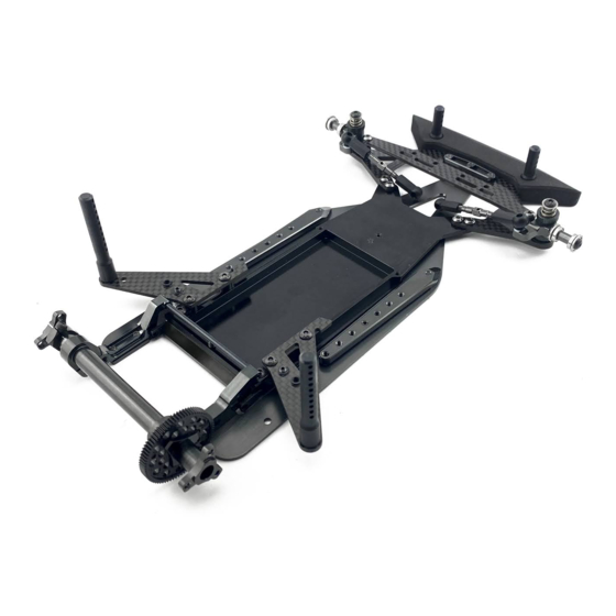
- Page 1 1/12-SCALE ELECTRIC ON-ROAD CAR INSTRUCTION MANUAL...
-
Page 2: General Precautions
UAB Awesomatix do reserve all rights to change any specifications without prior notice. All rights reserved. ASSEMBLY NOTES You can find the useful tips of A12 assembling and the A12 editable setup sheet on the Internet site: http://site.petitrc.com/reglages/awesomatix/setupa12/ GENERAL PRECAUTIONS •... - Page 3 STEP 1 AM1206 C1205 SH1.5W SH1.5W C1204 SF3X10 SF3X10 Note: SH1.5W is 7.4x3x1.5mm alloy spacer. STEP 2 SB3X5AL x2 SB3X5AL x2 Note: SB3X5AL is 3x5mm alloy screw. AM1203...
- Page 4 STEP 3 AM1205 AM1205 AM1204 SF3X6 SF3X6 STEP 4 Use blue “soft” thread lock for SS3X4 screw! SS3X4 OR125 SH1.5W OR125 ST1205 ST1205 ST1209L ST1209M Note: Add small amount of a joint grease between ST1205 and ST1209M/L. Rear ball joint Front ball joint Note: SS3X4 set screw tips should just slightly touch AM1204 chassis surface.
- Page 5 STEP 5 STEP 6 Note: Add ~0,3 g of 50 000...100 000 cst silicone oil Note: Add a bit of silicone oil into groove of ST1202. into cavity of ST1204 damper case. We recommend 100 000 cst silicone oil as the base setup. Keep ST1204 upright for several minutes until all oil reaches the bottom of the cavity.
- Page 6 STEP 8 Repeat the STEPS 5,6,7 for other side of ST1204 and check that both ST1202 rotors reached the desirable position (flush with the ST1204 face) Note: These faces of ST1204 and ST1202 should coincide. STEP 9 SB3X5 SB3X5 Note: SS3X10 set screw is used for adjusting of the rear downstop. An exact position of this SS3X10 screw will be set later during setup of the car.
- Page 7 STEP 10 ST1201 3mm Ball Stud ST1201 AM1207 ST1203 ST1201 AM1202 STEP 11 Note: ST1201 ball studs should be placed into slots of ST1202 rotors. SF3X5 x2 SF3X6 x2...
- Page 8 STEP 12 Short and +1mm longer wheelbase Note: Assortment of SH shims is used for settings are possible. setting of the desired rear ride height. Note position of SS3X5 screws. AT1203 SH0.25 SH0.5 SH1.0 SS3X5 SH1.75 Short wheel base SS3X5 SH0.25 SH0.25...SH1.75 SH0.5...
- Page 9 STEP 14 1,5mm hex driver or optional RHG 4.2 probe Note: ST1208 steering block posts provide 4 deg caster. Optional ST1208-C5 posts provide 5 deg caster. ST1208 AT1206 The tip of 1,5mm hex driver or optional ST1208 RHG 4.2 probe is used for alignment of the appropriate holes of ST1208 and C1205.
- Page 10 STEP 16 Note: SPR12FS Front Soft Springs (Silver) and SPR12FM Front Medium Springs (Gold) come in the A12 kit. SH12S-0.2 0.2mm thickness shims are used to set the front spring preload and the front ride height.
- Page 11 STEP 17 Installation of the standard mini servo. Installation of the SANWA SRG servo. SB3X5AL C1201 SH1.0 SB3X5AL SB3X5AL C1201 SB3X5AL SH1.0 AT1202 ST24-4.0 x2 SH0.25 SB3X6 ST24-4.0 x2 SANWA SRG servo (not included!) AT1202 SH0.25 Servosaver (not included!) SB3X6 Mini servo (not included!) Up to 35x30x15mm mini Servosaver (not included!)
- Page 12 Rear body holders assembling. STEP 20 Note: Press P06-1 collars into C1203 from lower face of C1203 and apply a drop of CA glue to set them. CA glue (not included) C1203 P06-1 P06-1 Use this hole for the side spring as the base setting. ST1211 Initial position of the side spring.
- Page 13 STEP 22 Note: Use thin double sided tape to secure P1215 foam bumper on C1204 bumper plate. P1215 P14-2 P14-2 P14-2 P14-2 SB3X10 Motor (not included) SB3X10 SF3X10 SF3X10 SH0.25 SH0.25 SB3X8 SB3X10 STEP 23 Note: Use OR91 9x1mm o-ring with the thick spur gears.
- Page 14 STEP 24 SC25X8 AT1207 SH12R3.5 SH12R2.0 SC25X8 SH12R0.5 Note: The second SC25X8 M2.5x8 screw is used for perfect axle balancing of the left wheel hub. SH12R0.5 SH12R2.0 Note: The second SC25X8 M2.5x8 screw is used for Note: The set of SH12R*** spacers shown ensures perfect axial balancing of the left wheel hub.
- Page 15 STEP 25 STEP 26 Note: Combination of SH12F0.5 spacers on both sides of the front wheel is used for the front width adjustment. Front 1/12 wheel (not included) B156 SH12F0.5 B156 SB3X5 Pinion gear (not included) Rear 1/12 wheel (not included) SC3X5 x3 SC3X6 x3 Note:The sum of the 64P spur+pinion teeth should...
- Page 16 RHG 4.2 gauge is designed for setting and measuring the ride height under rear damper of the A12 car (DRH - Damper Ride Height) and can be also used for setting and measuring of the front ride height (FRH) and the rear ride height (RRH).
- Page 17 These beams act as springs when the screws in them press on the AM1204 chassis plate. A12 setup sheet includes two values for the rear ride height. DRH 1 shows the ride height resulting from side spring pressure only, without the use of AM1205 side beams. DRH ride height is the final ride height of the car (which can be a combination of both side springs and side bars to reach this final desired height).
- Page 18 When using big tires, you will need to use shims under the C1205 to obtain the desired ride height. Placing shims under the steering block will not be sufficient to lower the ride height to proper height with larger tire sizes, so please use this additional method of adding shims under the C1205 C1205 SH0.25...SH1.0 x7...
-
Page 19: Setup Sheet
SETUP SHEET VERSION 1.0 DATE TEMPERATURE AIR / TRACK °C °C NAME COUNTRY ASPHALT OUTDOOR INDOOR CARPET TRACK CONDITION BUMPY FLAT RACE TECHNICAL MIX ED FAST TRACTION TRACK MEDIUM HIGH SUSPENSION PLATE STEERING HUB POSTS C1205 ST1208 SERVO PLATE C1205-ZT ST1208-C5 C1205AL OTHER... -
Page 20: Spare Parts
Bumper Plate SF3X10 M3x10 Flat Head Screw C1205 Suspension Plate SB3X5AL M3x5 Alloy Screw SPR12FS Front Spring Soft STS-A12 A12 Stickers Sheet SPR12FM Front Spring Medium SIO100K 100k silicone oil Optional parts Parts # Description RHG 4.2 Ride Height Gauge... - Page 21 WWW.AWESOMATIX.COM UAB “AWESOMATIX” Email: support@awesomatix.com All rights reserved. Copyright UAB “Awesomatix” 2020.
Need help?
Do you have a question about the A12 and is the answer not in the manual?
Questions and answers