Robopac S6 Use And Maintenance Manual
Self propelled wrapping robot
Hide thumbs
Also See for S6:
- Use and maintenance manual (115 pages) ,
- Use and maintenance manual (84 pages)
Table of Contents
Advertisement
ENG
USE AND MAINTENANCE MANUAL
Self propelled wrapping robot
ROBOT S6
Translation of the original instructions
3709301826.1
Code:
0117
Edition:
__________ SERIAL NUMBER __________
____________________________________________________________________________________________________________
ATTENTION
Read and understand these instructions before using the machine.
Keep this handbook for further consultation
ROBOPAC S.p.A.
Advertisement
Table of Contents

Related Manuals for Robopac S6


Summary of Contents for Robopac S6
- Page 1 USE AND MAINTENANCE MANUAL Self propelled wrapping robot ROBOT S6 Translation of the original instructions 3709301826.1 Code: 0117 Edition: __________ SERIAL NUMBER __________ ____________________________________________________________________________________________________________ ATTENTION Read and understand these instructions before using the machine. Keep this handbook for further consultation...
-
Page 2: Table Of Contents
ROBOT S6 Summary GENERAL INFORMATION 1.1. PURPOSE OF THE MANUAL 1.2. MANUFACTURER AND MACHINE IDENTIFICATION 1.3. TERMS AND DEFINITIONS 1.4. MODES OF REQUESTING FOR ASSISTANCE 1.5. ATTACHED DOCUMENTATION 1.6. HOW TO READ THE DIRECTIONS FOR USE SAFETY INFORMATION 2.1. GENERAL SAFETY PRECAUTIONS 2.2. - Page 3 ROBOT S6 5.3. "FRD TYPE SPOOL CARRIAGE" FORNET 5.4. "PDS" REEL TROLLEYS FOR CHANGING THE DRAWING RATIOS 5.5. REEL CARRIAGE LIFTING CHAIN ADJUSTMENT 5.6. BRAKE ADJUSTMENT 5.7. STEERING ARM RETURN SPEED ADJUSTMENT 5.8. ADJUSTING THE HEIGHT OF THE SENSING ARM WHEEL 5.9.
- Page 4 ROBOT S6 10.4. BATTERY DOCUMENTATION ENERSYS 10.5. BATTERY DOCUMENTATION EXIDE 10.6. BATTERY DOCUMENTATION MIDAC 10.7. CE STATEMENT OF CONFORMITY 4/94...
-
Page 5: General Information
ROBOT S6 1. GENERAL INFORMATION 1.1. PURPOSE OF THE MANUAL ‒ The manual is an integral part of the machine and is aimed to provide the operator the instructions for use in order to prevent and reduce the risks that arise from man-machine interface. -
Page 6: Terms And Definitions
ROBOT S6 Machine model. Machine’s serial number. Year of manufacture. Power supply voltage. Power supply frequency. Power supply phases. Electrical power consumption. Total installed power. Air consumption. Max. air supply pressure. Machine weight. Manufacturer’s name. 1.3. TERMS AND DEFINITIONS Some recurring terms found within the manual are described in order to provide a more complete image of their meanings. -
Page 7: Modes Of Requesting For Assistance
ROBOT S6 1.4. MODES OF REQUESTING FOR ASSISTANCE The distribution network ROBOPAC is at your service for any problem that requires technical support, to order spare parts, and for whatever new type of need that can help develop your business. -
Page 8: Safety Information
ROBOT S6 2. SAFETY INFORMATION 2.1. GENERAL SAFETY PRECAUTIONS ‒ Carefully read the "Instructions for use" specified in the manual and those applied directly to the machine. It is important to dedicate a little time to read the "Instructions for use" in order to minimise the risks and avoid unpleasant accidents. -
Page 9: Safety Warnings For Use And Operation
ROBOT S6 ‒ Install the machine in environments (artisan and industrial) with a flat surface that has no bumps so as to move easily round the pallet. ‒ Dismantle all the packaging components in compliance with the standards in force in the country of installation. -
Page 10: Employer Obligations
ROBOT S6 ‒ DO NOT allow the machine to be used by operators that are not properly trained, informed and unauthorised. ‒ Do not use the machine as a lifting device or as a rest surface for work activities (for example, a workbench). -
Page 11: Safety Warnings For Regulations And Maintenance
ROBOT S6 ‒ Danger of arms crushing To close the battery cover, lower it slowly to avoid trapping your hands. ‒ Body crushing hazard Do not linger in the machine operating area. ‒ Body crushing hazard Do not linger in the machine operating area. -
Page 12: Safety Warning For Electrical Equipment
ROBOT S6 ‒ Replace the components ONLY with ORIGINAL PARE PARTS or with SIMILAR design and functional features. The use of similar but non-original spare parts may lead to improper repairs, altered performance and economic damage. The components and/or safety devices shall be replaces ONLY with original spare parts to avoid altering the provided safety level. - Page 13 ROBOT S6 For each sign is specified the relative description. Information sign: It indicates that the “the battery should be charged in a suitable and well-ventilated environment, outside the working area”. Prohibition sign: Do not use your hands to intervene on the component.
-
Page 14: Surrounding Areas
ROBOT S6 2.9. SURROUNDING AREAS The illustration depicts the perimeter work areas of the machine. Machine's operating area. Sorrounding area. 14/94... -
Page 15: Technical Information
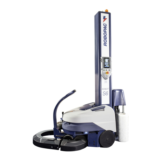
3. TECHNICAL INFORMATION 3.1. MACHINE GENERAL DESCRIPTION ‒ The S6-series ROBOT is a semiautomatic self-propelled machine designed to wrap and stabilize palletized loads using a stretchable film. ‒ The machine is suitable for installation in workshops and factories, protected against weather conditions. - Page 16 ROBOT S6 The following list provides a description of the main components and their functions. Slide column: for the vertical handling of the reel carriage. Roll-holder carriage: It includes a series of stretching and prestretching devices. For further details refer to the table "Roll-holder Carriage Specifications".
-
Page 17: Roll-Holder Carriage Specifications
ROBOT S6 3.1.1.ROLL-HOLDER CARRIAGE SPECIFICATIONS Type of reel General Requirements holdingcarriage FRD and “FRD for net” type reel carriage; with friction roller, mechanical brake and manual film stretch adjustment. FR type reel carriage with friction roller, electromagnetic brake and film stretchadjustment from the control panel. - Page 18 ROBOT S6 ‒ Single wrapping: It starts at the base of the pallet with a series of stabilizing windings and then stops at the top of the pallet with a closing winding. To start a new wrapping phase from the base, the roll-holder carriage must be lowered using the manual controls.
-
Page 19: Safety Device Descriptions
ROBOT S6 3.3. SAFETY DEVICE DESCRIPTIONS The figure shows the position of the safety devices, whose description and function is provided in the following list. Safety bumper: In case of collision against an obstacle, it stops the machine run and the wrapping cycle. -
Page 20: Description Of The Electrical Devices
ROBOT S6 3.4. DESCRIPTION OF THE ELECTRICAL DEVICES The figure shows the positioning of the devices on board of the machine. Electric motor: it activates the driving wheel. Gear motor: activates movementof the spool carriage. Batteries: They provide power supply to the electric motors and the circuit. -
Page 21: Description Of Accessories On Request
ROBOT S6 3.5. DESCRIPTION OF ACCESSORIES ON REQUEST To enhance the performance and to increase the versatility of the machine, the manufacturer furnishes the accessories listed below. ‒ Non-stain wheels: wheels made of a material that reduces stain formation on the floor. -
Page 22: Technical Specifications
ROBOT S6 3.6. TECHNICAL SPECIFICATIONS The figure and table specify the dimensional characteristics and technicaldata of the machine. 3.6.1.MACHINE AND PALLET DIMENSIONS Description Units of measurement Total machine length (A) 1825 Machine width (B) Machine width (C) with feeler 1183... -
Page 23: Technical Features
ROBOT S6 (E) max = 3100 3430 3605 Sliding column max. height (L) (E) max = 2400 2756 (E) max = 2800 3156 (E) max = 3100 3356 3.6.2.TECHNICAL FEATURES Description Units of measurement Lead-acid batteries 12V 110 Ah (capacity referred to a 5 h... -
Page 24: Coil Technical Specifications
ROBOT S6 3.7. COIL TECHNICAL SPECIFICATIONS 3.7.1.REEL FEATURES Description Units Value measur‑ ement Film spool dimensions (A) Maximum external diameter (D) Reel height (H) Film thickness μm 17÷35 Internal diameter (d) 50 ¹ - 76 Max weight Net spool dimensions (B) -
Page 25: Installation Environment Characteristics
ROBOT S6 3.9. INSTALLATION ENVIRONMENT CHARACTERISTICS Careful consideration must be given to the place where the machine is to be installed, in order to ensure that it may be easily operated, without creating any unnecessary risks for personnel. Therefore we suggest the following prerequisites: ‒... -
Page 26: Information On Handling And Installation Operations
ROBOT S6 4. INFORMATION ON HANDLING AND INSTALLATION OPERATIONS 4.1. RECOMMENDATIONS FOR HANDLING AND LOADING ― Before performing any operation, the authorised operator must make sure that he/she understood the "Instructions for use". ― Carefully read the "Instructions for use" specified in the manual and those applied directly to the machine and/or the package. -
Page 27: Loading And Transportation
ROBOT S6 Package in crate Cardboard box packaging 4.3. LOADING AND TRANSPORTATION Transport, also according to the destination, can be performed by different vehicles. The diagram represents the most popular solutions. Important Transport the machine suitable means of adequate capacity. -
Page 28: Installation Of Dismounted Parts
ROBOT S6 4.4. INSTALLATION OF DISMOUNTED PARTS Proceed as indicated. 4.4.1.INSTALLATION (WITH TILTED COLUMN) Fasten the lifting device to the eyebolt (A) to keep the column in position. Remove the support (B). Lift the column (C). Tighten the clamping screws (D-E). -
Page 29: Installation Of The Wheel Feeler And Tiller
ROBOT S6 Hook the lifting device to theroll-holder carriage (G). Lift the roll-holder carriage (G) and bring it close to the column,then secure it with thescrews (H). Remove casings (L). Connect the electric connectorsto the terminal board of theroll-holder carriage. - Page 30 ROBOT S6 Turn the rudder (M), connect the connectors (R) and insert it into the machine's support. Lift the rudder (M) and fix it with the screws (N). 30/94...
- Page 31 ROBOT S6 Assemble the wheel feeler (P) and secure it with the screws (Q). Important To install the rudder and the feeler, use the nuts and bolts supplied with the machine. 31/94...
-
Page 32: Lnstallation Of Rudder With Lightened Steering Wheel (Optional)
ROBOT S6 4.4.4.LNSTALLATION OF RUDDER WITH LIGHTENED STEERING WHEEL (OPTIONAL) Repeat the operations, mentioned in paragraph “Installation of the feeler and of the rudder”. Attach the rope (S) to the sheet metal (T). Important To lower the rudder (V) pull the handle (U). -
Page 33: Information On Adjustments
ROBOT S6 5. INFORMATION ON ADJUSTMENTS 5.1. RECOMMENDATIONS FOR ADJUSTMENTS ‒ Before performing any operation, the authorised operator must make sure that he/she understood the "Instructions for use". ‒ Before carrying out any intervention, activate all the safety de-vices provided, stop the machine and assess if any residual energy is still present. -
Page 34: Pds" Reel Trolleys For Changing The Drawing Ratios
ROBOT S6 5.4. "PDS" REEL TROLLEYS FOR CHANGING THE DRAWING RATIOS Proceed as indicated. Stop the machine in safety conditions. Remove transmission cover (A). Loosen the belt (C) through the tensioner (B). Remove the belt from the pulley (D). Loosen the screws (E). -
Page 35: Reel Carriage Lifting Chain Adjustment
ROBOT S6 300% (∗) (∗) (∗) See spare parts catalogue. Assembly the small plate and correctly fix it to the gear of the new driving ratio. Assembly the gear of the new driving ratio. Position the gear with the side of the small plate coupled to the friction. -
Page 36: Brake Adjustment
ROBOT S6 Re-tighten the nuts up to the surface of the chain tightening pulley. Undo screw (C). Refit the guard (A). 5.6. BRAKE ADJUSTMENT Proceed as indicated. Lift the machine and rest it on a support. Make sure that the machine is resting correctly, to prevent the risk of crushing during the operation. -
Page 37: Steering Arm Return Speed Adjustment
ROBOT S6 5.7. STEERING ARM RETURN SPEED ADJUSTMENT Use the screw (A) to adjust the steering arm return speed. The speed of the steering arm must not be too high to avoid causing personal safety risks. 5.8. ADJUSTING THE HEIGHT... -
Page 38: Standard Feeler
ROBOT S6 5.9.1.STANDARD FEELER Lower the rudder (A). Lift the hood (B). Grip the lever (C). Connect the lever (C) to the tightener (D). Adjust the tightener (D) following its path. Disconnect the lever (C) from the tightener (D). Put back the lever (C). -
Page 39: About The Use
ROBOT S6 6. ABOUT THE USE 6.1. RECOMMENDATIONS FOR OPERATION AND USE ‒ Before performing any operation, the operator must make sure that he/she understood the "Instructions for use". ‒ When using the machine for the first time, the operator must read the manual and identify the controls and simulate some operations, especially the start-up and shutdown. - Page 40 ROBOT S6 ‒ By touching each area with your finger the relevant functions are displayed. ‒ There are two automatic wrapping cycle controls: standard CONTROL and MULTI-LEVEL CONTROL (from the screen “layer home”). ‒ MULTI-LEVEL CONTROL allows you to divide the height of the product in 5 different levels, all of which...
- Page 41 ROBOT S6 The illustration shows the logic functional diagram of "navigation" modes. 41/94...
- Page 42 ROBOT S6 42/94...
-
Page 43: Numeric And Alphanumeric Keypad
ROBOT S6 6.3.1.NUMERIC AND ALPHANUMERIC KEYPAD Some values displayed on the areas of each single screenshot can be properly programmed. The keypad is displayed each time you press an area that can be modified or programmed. After entering the characters (numeric or alphanumeric), press the button to confirm. -
Page 44: Home" Screenshot
ROBOT S6 Coating stretching Coating pre-stretching Trolley lifting speed Trolley lowering speed Machine forward speed Film height adjuster – creasing device Push-button: used to close the schedule window. Bar: used to increase or decrease (quickly) the value displayed in the area (E). - Page 45 ROBOT S6 Button: it is used to copy the data of one layer onto another. Note. For a description of the keys P, Q, R, T2, T3, T4 and T5 see the chapter “wrapping cycle screen”. Wrapping cycle. Distance from the ground of wrapping start.
-
Page 46: Manual Handling" Screenshot
ROBOT S6 ‒ Push-button: used to display the upper level screenshot. ‒ Push-button: used to display the "Home" screenshot. 6.5. "MANUAL HANDLING" SCREENSHOT The controls to activate the vertical handling of the spool carriage in “manual” operation mode are displayed. -
Page 47: Recipes" Screenshot
ROBOT S6 6.6. "RECIPES" SCREENSHOT The screenshot displays the controls to activate the desired recipe. Push-buttons: used to activate the recipe concerned. Red coloured background: function activated. Push-button: used to program the name of the recipe. Area: displays the preview of the pallet wrapping cycle selected. -
Page 48: Level Copy" Screen
ROBOT S6 6.6.2.“LEVEL COPY” SCREEN To copy and move the parameters from one level to another, use the following buttons: Push-button: press +/- to change the starting level and destination. Push-button: press to confirm the operation (Enter). Push-button: used to go back to the “home”... - Page 49 ROBOT S6 Area: It displays the name of the set of parameters being programmed. Area: displays the preview of the pallet wrapping cycle selected. Push-button: used to select the type of wrapping cycle of the pallet. At each activation, the push-button...
-
Page 50: Screenshot "General Parameters
ROBOT S6 6.8. SCREENSHOT “GENERAL PARAMETERS” The screenshot is used to program the operating parameters of the machine. Push-button: used to display the "production counters (pallets)" screenshot. Push-button: used to display the "enabling (H.M.I.)" screenshot. Push-button: used to display the "Service"... -
Page 51: H.m.i. Settings" Screen
ROBOT S6 6.10. “H.M.I. SETTINGS” SCREEN The screenshot displays the controls to customize the operating mode of the user interface". Push-button: used to display the screenshot showing the software version. Button: it shows the "Date/ time setting" screen. Push-button: used to display the "password modification"... -
Page 52: Service" Screenshot
ROBOT S6 Push-button: used to select the type of user concerned. At each activation, the push-button displays the function enabled with the reference icon. ‒ A1 Icon: used to select the "machine responsible" user. ‒ A2 Icon: used to select the "assistance service"... -
Page 53: Programming A New Recipe
ROBOT S6 Area: It displays the name of the set of parameters being programmed. Button: it selects the type of "special cycle" wrapping. Press control several times in order to show the desired function. ‒ Function "F0": it disables the wrapping with "special cycles". -
Page 54: Wrapping Start And Stop
ROBOT S6 Check the type of function shown in button (G) in order to programme the desired wrapping. ‒ Wrapping without "special cycles". press button (G) until function "F0" is shown. ‒ Wrapping with "special cycles". press button (G) until function "F1" (large products) or "F2" (cylindrical products) is shown. -
Page 55: Film Coil Feeding
ROBOT S6 ‒ When the machine in "stand-by" mode is not used for over 15 minutes, it automatically enters the "energy saving" mode. To resume operation, touch the machine display. If the “power saving” function stays on for more than 60 minutes, the machine automatically turns off. -
Page 56: Adjusting Cutting
ROBOT S6 ‒ On reel carriages type "PVS", to allow film unwinding, it is necessary to press the roller rotation button (E) on the reel carriage. 6.18. ADJUSTING CUTTING The table shows the values of the parameters P9 and P10 to be set for the automatic cutting of the coating. - Page 57 ROBOT S6 Proceed as indicated. Switch the machine off. Lift the battery cover (A). With the additional battery kit, simply replace the basket with empty batteries (see “Battery replacement”) with the basket containing the charged batteries. Insert the plug into a socket.
-
Page 58: Maintenance Information
ROBOT S6 7. MAINTENANCE INFORMATION 7.1. MAINTENANCE INSTRUCTIONS ‒ A good maintenance will allow for a longer working life and constant compliance with the safety requirements. ‒ Before performing any operation, the authorised operator must make sure that he/she understood the "Instructions for use". -
Page 59: Lubrication Point Diagram
ROBOT S6 Every 5000 hours Reduction gears Change the See “Lubrication and gearmotors lubricant ¹ point diagram” ∗ or 50000 cycles ¹ Do not top-up and/or replace the lubricant in reduction gears and gearmotors lubricated for life. ∗ The cycle-based frequency was defined according to the standard cycle. -
Page 60: Lubricants Table
ROBOT S6 Check lubricant level. Do not top-up and/or replace the lubricant in reduction gears and gearmotors lubricated for life. Keep to the recommended lubrication frequency to get top machine performances and a longer operating life. Use lubricants (oils or grease) recommended by the manufacturer or with similar chemical- physical features. -
Page 61: Troubleshooting
ROBOT S6 8. TROUBLESHOOTING 8.1. ALARM MESSAGE LIST AND INFORMATION In the event of a breakdown during operations the machine stops automatically and alarm messages appear on the display. The table lists the displayed messages, the type of problem, the cause and possible solutions. - Page 62 ROBOT S6 - STRETCH DRIVER Alarm at the film A failure Check the motor OVERTEMP. stretching motor. occurred to the and refer to the - STRETCH DRIVER film stretching wiring diagram. SHORT CIRCUIT. motor. - STRETCH DRIVER UNDERVOLT. - STRETCH HEAT SINK OVERTEMP.
- Page 63 ROBOT S6 - ALL. BATTERY Charge battery Battery charge Check the battery CHARGER. alarm. failure. charger and refer to the wiring diagram. - H.M.I. COMUNIC. Communication The cable is Check the FAULT. alarm at the unplugged or the operation of the touch screen.
-
Page 64: Spare Parts Replacement Information
ROBOT S6 9. SPARE PARTS REPLACEMENT INFORMATION 9.1. RECOMMENDATIONS FOR REPLACING PARTS ‒ Before performing any operation, the authorised operator must make sure that he/she understood the "Instructions for use". ‒ Carry out the interventions with all the safety devices enabled and wear the DPI provided. -
Page 65: Machine Disposal And Scraping
ROBOT S6 ‒ Roller brake pad. (Only for spool carriages type "FRD"). ‒ Carriage clutch. (Only for spool carriages type "PDS"). ‒ Drive belt. (Only for spool carriages type "PDS" - "PVS"). ‒ Batteries. ‒ Front wheels. ‒ Rear wheels. -
Page 66: Enclosed Documentation
To utilise the warranty, the user must immediately notify the company that a defect exists, always referring to the machine serial number. ROBOPAC S.p.A., in its final judgement, will decide whether to replace the defective part or request it to be shipped for tests and/or repairs. -
Page 67: Battery Charger Operation Manual S
ROBOT S6 10.2. BATTERY CHARGER OPERATION MANUAL S.P.E. Shown below are the directions for use provided directly by the manufacturer of the commercial device, standard or optional, installed on the machine. The language of such documentation may not correspond to that in which the machine’s directions for use are written. - Page 68 CBHD1• CBHD2 • HF1-IP • HF2-IP ELECTRONIC BATTERY CHARGER OPERATING MANUAL Attention: read carefully the operating manual before using the battery charger 68/94...
- Page 69 Model Voltage Current Charging Curve lUla lUla lUla lUUo OTHER CBHD1 CBHD1 CBHD1 CBHD1 CBHD1 CBHD1 CBHD1 CBHD1 CBHD1 CBHD1 CBHD1 CBHD1 CBHD1 CBHD1 CBHD1 CBHD1 CBHD1 CBHD1 CBHD2 CBHD2 CBHD2 CBHD2 CBHD2 CBHD2 CBHD2 CBHD2 CBHD3 CBHD3 CBHD3 CBHD3 CBHD3 CBHD3 HF1-IP...
- Page 70 BATTERY CHARGER IDENTIFICATION LABEL Model Battery charger serial number Battery charger manufacture date Input voltage Output voltage and current Mains fuse value Charging curve Mains absorption Battery capacity range Product certification stamps 70/94...
- Page 71 Important safety instruction. Keep these instructions. This manual contains important instructions for the safety of the user and operation of the device. GENERAL WARNINGS 1) Before each use of the battery charger the instructions set out below must be carefully read and abided by.
- Page 72 22) The battery charger tolerance thresholds, as far as levels of over-voltage and overcharging are concerned, are used only for the safeguarding of the systems of the same and have no safety functions for the battery itself, the safety of which depends solely on the BMS, even when the battery charger is connected to the battery, whether the latter is being charged or not.
- Page 73 ELECTRONIC BATTERY CHARGER OPERATING MANUAL TECHNICAL FEATURES OF THE CBHD1 – CBHD2 - CBHD3 - HF1-IP The innovative characteristics of the CBHD1 – CBHD2 – CBHD3 - HF1-IP range of battery chargers are the following: Advanced technology High frequency system. Charging process fully controlled by microprocessor.
- Page 74 MAINS CABLE BATTERY CHARGER BATTERY CABLES 2x2,5mmq Example diagram of connection between battery charger and battery. MAINS CABLE BATTERY CHARGER AUXILIARY RELAY CABLES 2x1mmq INTERNAL EXTERNAL AUXILIARY RELAY RELAY (not 5Adc@24Vdc MAX supplied) BATTERY CABLES 2X2,5mmq Example diagram of connection with use of battery charger internal auxiliary relay. The auxiliary relay is Normally Off and switches on when the battery charger is turned on.
- Page 75 CE DECLARATION OF CONFORMITY According to: UNI CEI EN ISO/IEC 17050-1:2005 S.P.E. ELETTRONICA INDUSTRIALE di Poletti Sergio Via di Mezzo Ponente, 383 – 40014 Crevalcore (Bologna) ITALY Declare under our sole responsibility that the product: ELECTRONIC AUTOMATIC BATTERY CHARGER MODEL: to which this declaration applies, complies with the provisions of the Directives of the Council of the European Union on the approximation of the laws of the members states: Relating to Electromagnetic Compatibility (EMC) Directive 2004/108/EC of the European Parliament...
-
Page 76: Battery Charger Operation Manual Nordelettronica
ROBOT S6 10.3. BATTERY CHARGER OPERATION MANUAL NORDELETTRONICA Shown below are the directions for use provided directly by the manufacturer of the commercial device, standard or optional, installed on the machine. The language of such documentation may not correspond to that in which the machine’s directions for use are written. - Page 77 77/94...
- Page 78 78/94...
- Page 79 79/94...
- Page 80 80/94...
- Page 81 81/94...
- Page 82 ROBOT S6 10.4. BATTERY DOCUMENTATION ENERSYS Shown below are the directions for use provided directly by the manufacturer of the commercial device, standard or optional, installed on the machine. The language of such documentation may not correspond to that in which the machine’s directions for use are written.
- Page 83 Chapter 10 Annexes 10.3. BATTERY DOCUMENTATION ENGLISH Operation and m aintenance instructions pow erbloc dry M ot ive pow er bat t eries for sm all t ract ion Sealed gas recom binat ion m onoblocs XP series: AGM t echnology M FP series: Gel t echnology Rat ing dat a : 1.
- Page 84 Chapter 10 Annexes 2. Operat ion 3.1. Daily DIN EN 50272-3 “ Traction batteries for industrial trucks” is the standard • Recharge the battery after every discharge of m ore than 40% C w hich applies. • check: the condition of the plugs, cables and that all insulation covers The nom inal operating tem perature is 30°C.
- Page 85 85/94...
- Page 86 86/94...
- Page 87 ROBOT S6 10.5. BATTERY DOCUMENTATION EXIDE Shown below are the directions for use provided directly by the manufacturer of the commercial device, standard or optional, installed on the machine. The language of such documentation may not correspond to that in which the machine’s directions for use are written.
- Page 88 Chapter 10 Annexes Lead acid bloc batteries with positive flat plates (GiS) and positive tubular plates (PzS) 81700679 Range: FF and FT Maintenance free lead acid bloc batteries with positive flat plates (GiV) Range: GF-V, GF-Y, AF-X, AF-Z, AS, df-V und df-Y Operating Instructions Traction batteries Rating data...
- Page 89 Chapter 10 Annexes For commissioning of unfilled GiS/PzS-batte- 2.3 Equalising charge further testing and maintenance by the service ries see separate instructions. Equalising charges are used to safeguard the life department should be requested. of the battery and to maintain its capacity. They 2.
- Page 90 Chapter 10 Annexes Operating Instructions Traction Batteries with Dry-Charged Cells g) When charging is finished, the density of OPERATION the electrolyte must be the same for each cell, and be between 1,280 1,290 kg/l, a) Open plugs. at 30¯ C. b) Pour in the electrolyte at a temperature between 15¯...
- Page 91 ROBOT S6 10.6. BATTERY DOCUMENTATION MIDAC Shown below are the directions for use provided directly by the manufacturer of the commercial device, standard or optional, installed on the machine. The language of such documentation may not correspond to that in which the machine’s directions for use are written.
- Page 92 92/94...
- Page 93 93/94...
- Page 94 3710308617_001_0516 CE_GB EC DECLARATION OF CONFORMITY (Annex IIA DIR. 2006/42/EC) Robopac S.p.A. Via Fabrizio da Montebello, 81 - 47892 Gualdicciolo Republic of San Marino DECLARES THAT THE MACHINE Robopac S.p.A. Via Fabrizio da Montebello, 81 47892 – Gualdicciolo Repubblica di San Marino http://www.aetnagroup.com/...
Need help?
Do you have a question about the S6 and is the answer not in the manual?
Questions and answers
what battery is needed
What is the process for charging the batteries
what is the proper way to adjust corner counting sensor on a S6. also a local company that services the machine